Abstract
In this work, a novel electronic lock that can encode and decode optical signals, modulated using Morse code conventions, was developed to build a smart home security system based on the Internet of Things (IoT). There are five topics of interest in this research: (1) optical Morse code encoder; (2) optical Morse code decoder; (3) ambient light sensor circuit; (4) fuzzy controller; (5) cloud monitoring system. We take advantage of the light-emitting components as the encoder, which are readily available in hand-held mobile devices (e.g., Smart phones) and photoresistors and a microcontroller as the decoder. By Wi-Fi transferring, even without a personal computer, real-time information about this lock can be uploaded to the cloud service platform, and helps users to ensure home safety on the remote monitoring system. By using the ambient light sensor and fuzzy controller in this novel optical Morse code-based electronic lock, experimental results show that the reliability of this system is much improved from 65% to 100%. That means that it is highly resistant to different illumination conditions in the work environment, and therefore all functions, including coding, emitting, receiving, decoding, uploading and cloud monitoring, can work well. Furthermore, besides the convenience and cost reduction, by incorporating traditional keys into smart phones, as a consumer electronics, our proposed system is suitable for users of all ages because of a user-friendly operation interface.
1. Introduction
The advancement in nano-semiconductor manufacturing opens up the era of the internet of things. Nowadays, nearly every item in our daily life, from mobile, tablet, watch, refrigerator to even glasses, can be interconnected over Wi-Fi, a global system for mobile communication (GSM), near field communication (NFC), bluetooth, zigbee and multiple other wireless communication technologies [1,2,3,4]. It is needless to say that people could tackle major tasks as well as trivial real-time tasks at their fingertips with the help of simple hand-held devices. However, the application of the Internet of Things is still very restricted due to price, lack of system integration, unfriendly user interface, and no Wi-Fi access in the surrounding area. Among these, the home security system guarding people’s lives and properties is one of the issues that needs further research and urgent improvement.
The old-fashioned key-and-lock is still widely used in the home security system today. With urbanization and diverse criminal types, its efficacy is being challenged. In recent years, governments, schools, companies and even large communities have started to use the radio frequency identification (RFID) instead. Nonetheless, the virtual RFID card is an extra accessory to the user and is prone to being lost or embezzled. Therefore, it is not as convenient as the system that we propose here which utilizes common hand-held devices as electronic locks. Moreover, although there are face, fingerprint, speech and iris recognition systems that differentiate individuals by their unique biometrics, its accuracy is strongly affected by aging, injuries, illness and other uncertain factors that change these features. The biometric systems require extremely high sensor resolution, thereby increasing the product cost and restricting their popularization. Therefore, the future development trend of the household security industry is to develop a low-cost wireless digital door access system that has high convenience, high security, and high transmission speed.
Based on the above considerations, we proposed a brand-new optical Morse code-based electronic locking system by referring to the visible light communication (VLC) Technology, Light Fidelity (Li-Fi) [5,6,7], with the bandwidth 10,000 times higher than that of Wi-Fi. Such a system integrates the smart phone that is indispensable in modern times, with the door access system. It uses the light-emitting diodes (LED) component in smart phones as the encoder for optical Morse code, which not only meets the above requirements of low cost and high convenience, but also has the VLC advantages of high security and high transmission speed. Regarding the working principle, it encodes the Morse code for the data to be transmitted, and sends out the optical Morse code with the LED. Upon receiving the optical signals, the receiving end could decode and compare whether the data are correct. Finally, the real-time information of the lock will be uploaded to the cloud service platform, and users can ensure home safety on the remote monitoring system. Moreover, to avoid errors caused by ambient light, we proposed a novel control circuit based on expert knowledge and empirical laws. The new circuit showed satisfying results as it reaches 100% accuracy under all light intensity tested.
1.1. Internet of Things
As early as 1995, in the book The Road Ahead written by Bill Gates, Gates mentioned a prototypic idea of the Internet of Things that lost things would send out messages on their location to the owner. In 1999, professor Kevin Ashtin from Massachusetts Institute of Technology (MIT) suggested labelling everyday items with RFID and a sensoring system. Furthermore, in 2005, thanks to the prosperous advancement in smart phone technology, the International Telecommunications Union furthered these ideas and the formal definition of the “Internet of Things” appeared for the first time in its yearly report [8,9].
Internet of Things has three layers; from bottom to top, they are perception layer, transport layer, and application layer. The perception layer is the core of the system. It is responsible for gathering data and recognizing objects through wireless sensors. The transport layer, composed of the cloud computing system, integrates and uploads the collected information, and allows the upper layer to use it according to the need. Applications such as automatic control, communications, environmental monitoring and smart home, have been proposed. The applications of the Internet of Things is limitless and is definitely going to be an indispensable part of the future smart cities.
1.2. Morse Code
The history of Morse code dates back to the 1830s. It is a digitalized electrical text transmitted by on–off tones, lights or radio. Unlike the binary system of computer communication, Morse code symbols are either a text character (letter or numeral) or a pause represented by a unique sequence of dots and dashes organized into five statuses [10]. Morse code relies on precise intervals of time between dots and dashes, between letters, and between words. In this work, the dot duration is the basic unit of time measurement in code transmission, the dash duration is three time units long [11,12,13,14,15], and the other three statuses take up 0.2, 5, 7 units respectively.
As is known to us, many encoding systems are digitalized and use mature encoding/decoding algorithms, which are widely applied in the related door access system. However, they are accompanied with some security issues. On the contrary, the visible light Morse encoding application proposed in this paper, uses the Morse code that is more difficult to decoding than digital decoding. Moreover, it has limited usage scope as the visible light cannot penetrate the wall. Furthermore, being free from electromagnetic interference improves the system security and reliability.
Morse code could be subdivided into either a long or short coding system by the use of English characters and their complexity. The shorter version uses only Arabic numbers, 0–9, and is simpler than its longer counterpart. Table 1 shows the Morse code and its representing number in the short coding system which we used in this article; while Table 2 is the standard Morse code.

Table 1.
Morse code table (short version).
Table 2.
Morse code table (standard version).
1.3. Cloud Monitoring System
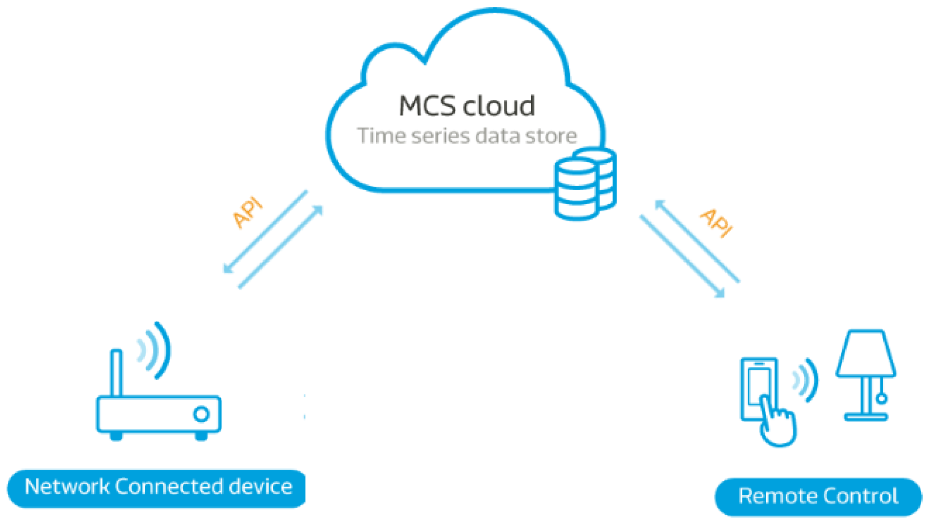
The Cloud is a vital part of the Internet of Things, allowing the transmission of information and application commands from the sensor to the end user. The MediaTek Cloud Sandbox (MCS), designed for the development kits of Linklt ONE series, was used as the service platform in our work [16]. Without building up a website server, users could check the real-time status of the optical Morse code-based electronic lock to ensure home safety by a remote monitoring app on their smartphones. Figure 1 shows how this system works.
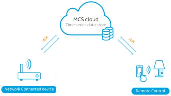
Figure 1.
System Architecture diagram of the MediaTek Cloud Sandbox (MCS). Where API is the application programming interface.
1.4. Fuzzy Theory
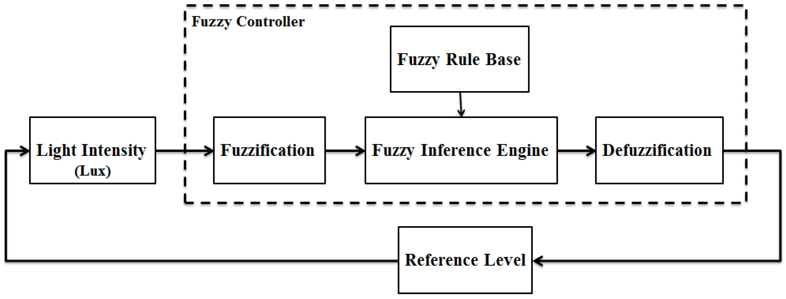
The system takes the photosensitive resistor as the major component for receiving. However, its sensitivity varies with the ambient light. To improve the stability of the system, we refer to Chatterjee, who use the Fuzzy compensator to calibrate the value of each output vector voltmeter; and the study method of Lei who takes the Fuzzy logic compensator to resolve the vibration issue of the adaptive controller [17,18], and finally use the Fuzzy controller as the conversion between the light and reference potential for compensation.
Traditional logic sets apply the binary system and denote all situations by either 1 or 0. This is contrary to our ways of thinking and it fails to fully describe the complexity as well as the uncertainty in the real world. Therefore, automatic controller specialist, Zadeh, pioneered the concept of fuzzy theory with a previous approximation model. Subdivision of 0 to 1 allows more possibilities and the theory is thereby able to cope with a more complicated non-linear system [19]. Compared to traditional controlling methods, fuzzy theory has less limitation to the real-word applications. Undoubtedly, it is becoming even more important as artificial intelligence (AI) technology gradually takes over the industry [20].
As shown in Figure 2, the fuzzy controller (surrounded by dash lines) is composed of four components: (1) Fuzzifier; (2) Fuzzy Rule Base; (3) Fuzzy Inference Engine; (4) Defuzzifier. The other two blocks, “Reference Level” and “Light Intensity (Lux)”, represent the reference voltage and the ambient light intensity, respectively.
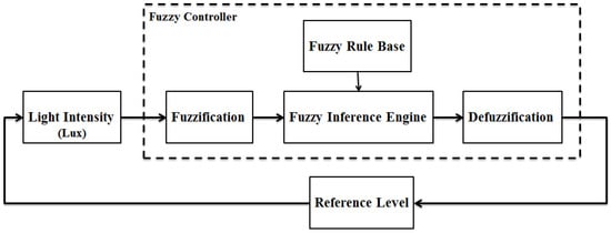
Figure 2.
System Architecture diagram of the fuzzy controller.
2. System Architecture and Device
There are five main topics of interest in this research: the optical Morse code encoder, the optical Morse code decoder, the fuzzy controller, the environmental photosensor circuit, and the cloud monitoring system. The work principle of the novel electronic lock is described as follows.
2.1. System Architecture
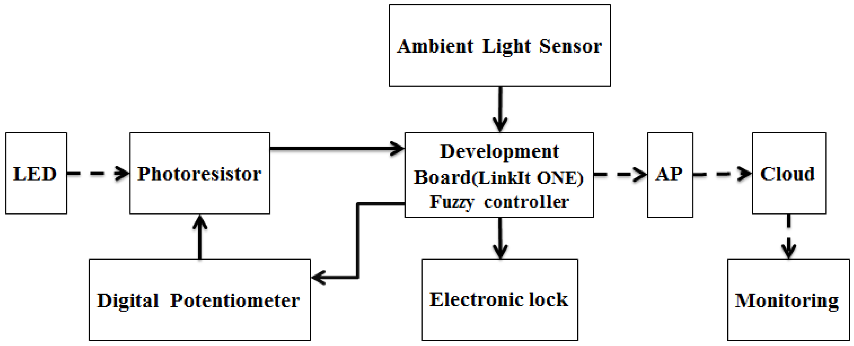
The system flow chart for our novel electronic lock is shown in Figure 3. Firstly, the mobile phone coded the user’s numerical ciphers into a set of Morse code and sent out the according flashlight signals generated by its light-emitting components (LED). Secondly, the decoder’s photoresistor depicted the optical analog signals received on a voltage–time coordinate to translate it back to their original Morse code set through the built-in microcontroller. Thirdly, the system compared the result with the user’s command. If the codes match, the electronic lock would be opened and simultaneous reports on the user’s identity, system condition and time would be uploaded to the MCS cloud monitoring system by Wi-Fi so that distant users could keep control on their home security.
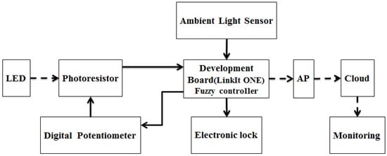
Figure 3.
System Architecture diagram of the novel electronic lock.
After the initial trial, we revised the system by substituting the original fixed resistor with a MCP41010 digital potentiator and used an environmental photosensor and fuzzy theory to prevent interference from ambient light. The new designed system worked as follows:
The environmental photosensor received ambient light intensity (Lux) as the input into the calculator to obtain the wiper for the digital potentiator control. In this circuit, both the photoresistor and the digital potentiator adjusted proportionally to lightening variables, resulting in a stable voltage output independent of ambient light intensity. As shown in our experimental results, the circuit dramatically enhanced the accuracy of the optical Morse-code decoder.
2.2. Hardware Setup
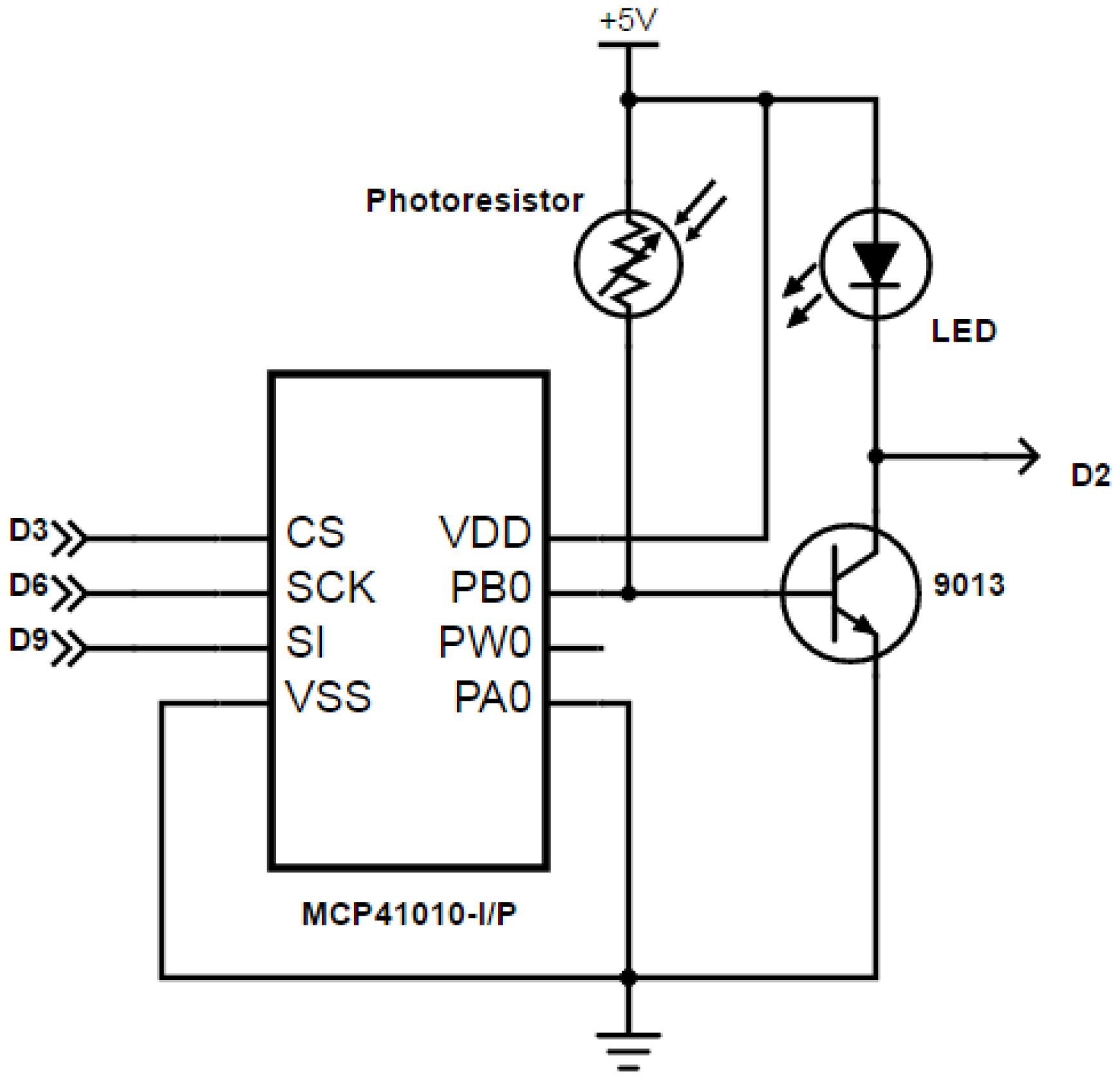
The system is based on the LinkIt ONE development board manufactured by MediaTek Inc. (Hsinchu, Taiwan) and Seeed Studio (Shenzhen, China) [21]. It is designed specifically for the Internet of Things and wearable devices. The greatest strength of this interface is that it has PC-independent, Wi-Fi-based direct connection to the code. Apart from this, it is loaded with MT5931 Wi-Fi components, MT3332 global positioning system (GPS) components, GSM, general packet radio service (GPRS), Bluetooth, Audio, a micro secure digital (SD) card and most Arduino UNO-compatible pins as shown in Figure 4 and Figure 5. Another point worth noticing is that even though the development environment of LinkIt ONE is Arduino integrated development environment (IDE)-based, it features an ARM7 EJ-S-cored, MT2502 microcontroller (Aster) instead of a common AVR controlling system.
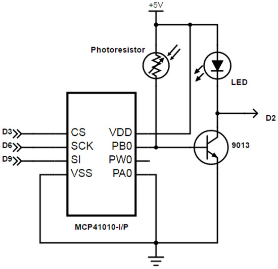
Figure 4.
The photosensitive resistor divider.
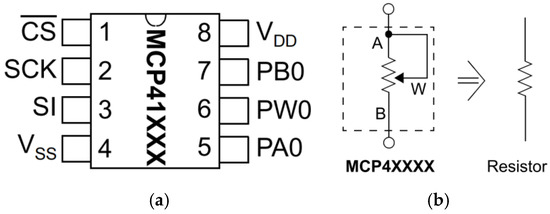
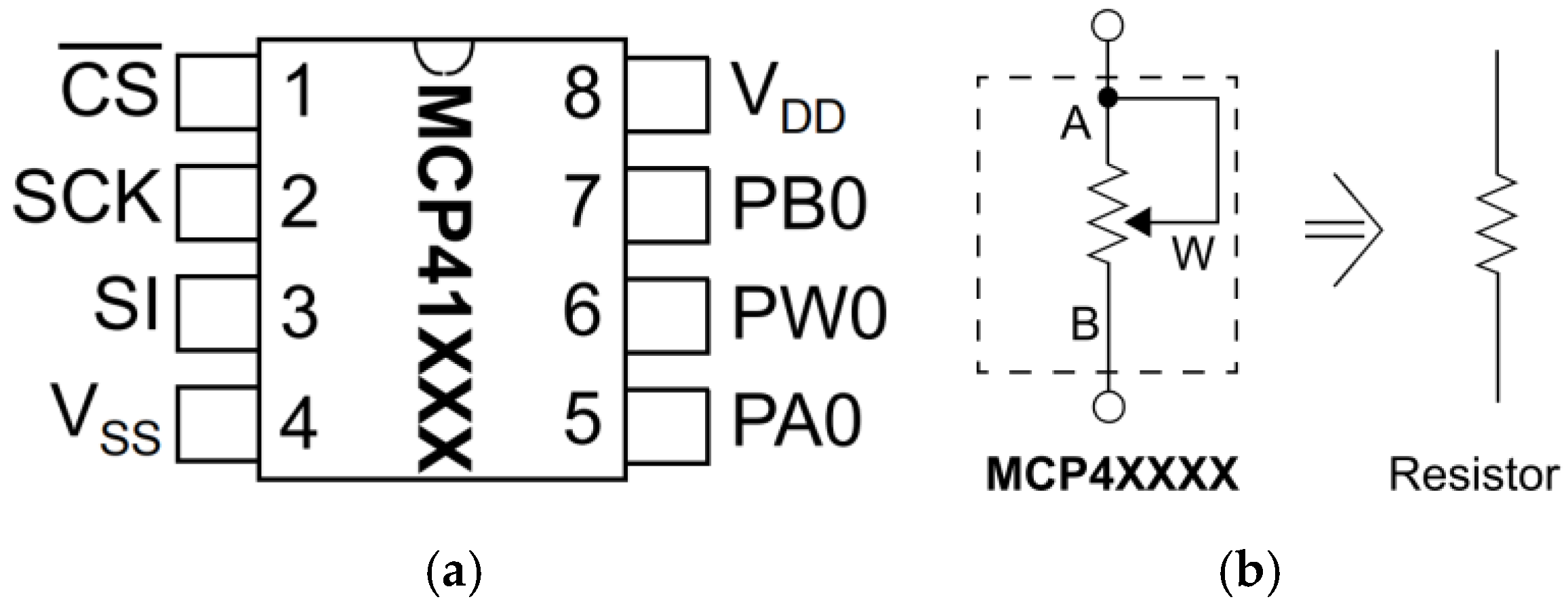
Figure 5.
MCP41010 (a) pin configuration; (b) two-terminal of the rheostat mode.
As illustrated in Figure 4, the photoresistor is connected to a 220 Ω limiting resistor in a serial circuit to protect the LED signaling light. The output of the photosensitive resistor divider containing a digital potentiometer MCP41010 and a photoresistor in parallel is connected to pin B of transistor 9031. Finally, Pin C of transistor 9031 is connected to pin D2 of LinkIt ONE, leading to signal magnification.
The MCP41010, shown in Figure 5a, is a digital potentiometer that is controlled using a serial peripheral interface (SPI). It is fully adjustable using 256 steps from approximately zero to 10 kΩ or about 39 Ω per step.
Digital potentiometer applications can be divided into two categories: rheostat mode and potentiometer (or voltage divider) mode. In the rheostat mode, the potentiometer is used as a two-terminal resistive element. The unused terminal should be tied to the wiper, as shown in Figure 5b. Reversing the polarity of the A and B terminals will not affect operation.
Using the device in this mode allows control of the total resistance between the two nodes. The total measured resistance would be the least at code 00H, where the wiper is tied to the B terminal. The resistance at this code is equal to the wiper resistance, typically 52 Ω for the 10 kΩ MCP41010 device. For the 10 kΩ device, the least significant bit (LSB) size would be 39.06 Ω. The resistance would then increase with this LSB size until the total measured resistance at code FFH would be 9.985 kΩ. The wiper will never directly connect to the A terminal of the resistor stack.
3. Experimental Methods
In this article, we substituted the fixed resistor of the photosensitive resistor circuit with a digital changeable resistor MCP41010 to prevent system errors caused by differences in the ambient light. Furthermore, the fuzzy controller stabilized the reference voltage through the following mechanism.
3.1. Calculation of Digital Resistance, Photosensitive Resistance and Reference Voltage
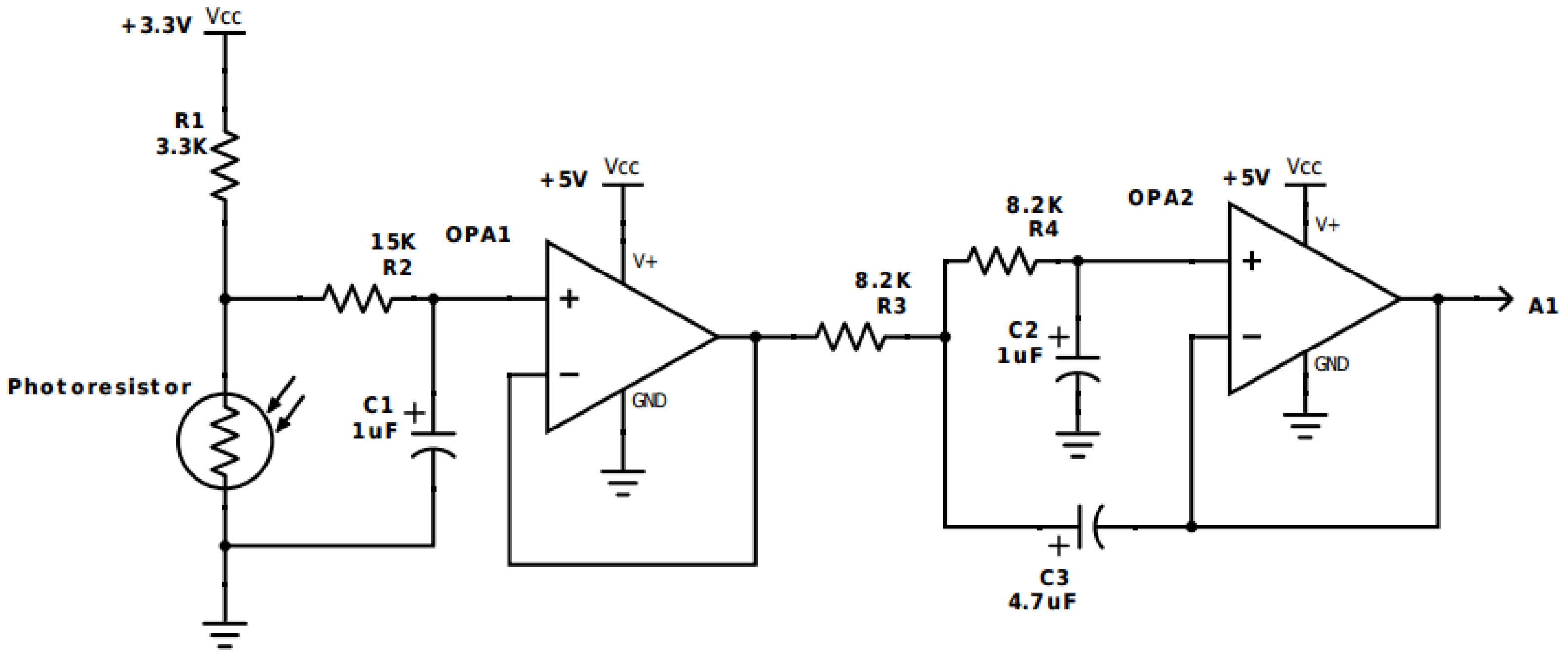
As shown in Figure 6 [22], the ambient light sensor circuit is a low-pass filter composed of two sets of operational amplifiers (IC TL072), a 1 μF capacitance, a 4.7 μF capacitance and an 8.2 kΩ resistor. This circuit only allowed signals with frequency less than 100 Hz to pass and its input is connected to the A1 analog pin of LinkIt ONE.
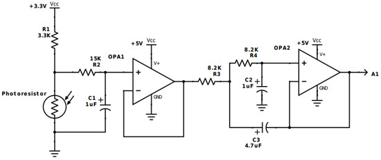
Figure 6.
Ambient Light Sensor, where GND is the ground V = 0.
The following Equations (1)–(3) are the equations for ambient light illuminance calculation used in our work:
where RL in Equation (1) represents the photosensitive resistance.
where in Equation (2), as demonstrated in Figure 6, indicates the output voltage between the photoresistor and the fixed 3.3 kΩ resistor.
Finally, after Lux is determined, we are able to get the digital resistance (Rv) of MCP41010 from Equation (4).
where RAB denotes the upper limit of the variable resistor and it is 10 kΩ for MCP41010. Dn obtained by the fuzzy controller, represents the 8-bit digital variable resistor of MCP41010 with value ranging from 0 to 225. For instance, when Dn = 50 H, Rv = 3.125 kΩ. Then, as shown in Figure 4, the output voltage of our optical Morse-code decoder, or the input voltage (VB) into the transistor 9013 could be obtain by Equation (5):
The CHD-1688 transformer specifically for computers (Input: AC 100–240 V, 50/60 Hz, 2 A, Output: DC 12 V, 2 A) is used in our system. Apart from the electronic lock, the power was also supplied to the voltage stabilizer IC (LM7805K) to feed DC 5 V to LinkIt ONE, which was connected to the ambient light sensor and the photosensitive resistor circuit.
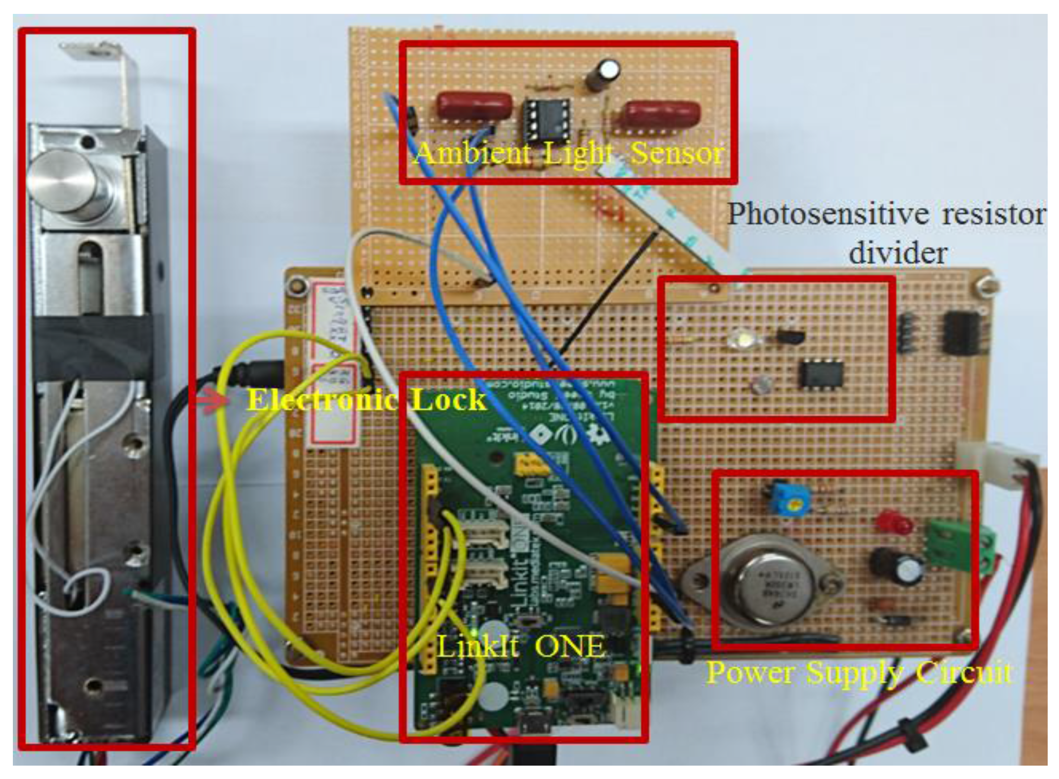
The complete hardware was shown in Figure 7. There were five main components in our work, including (A) system power supply circuit; (B) photosensitive resistor circuit; (C) development board (LinkIt ONE); (D) ambient light sensor circuit; (E) electronic lock.

Figure 7.
The complete hardware in our work.
3.2. The Application of Fuzzy Control
Compared to other controlling strategies, fuzzy control needs no accurate mathematical model. With expert knowledge and empirical laws, we can achieve precise control over the photosensitive resistor circuit under different ambient light intensity. The Matlab Fuzzy Toolbox is taken in our work. Detailed experimental methods and steps are as follows:
3.2.1. Fuzzication
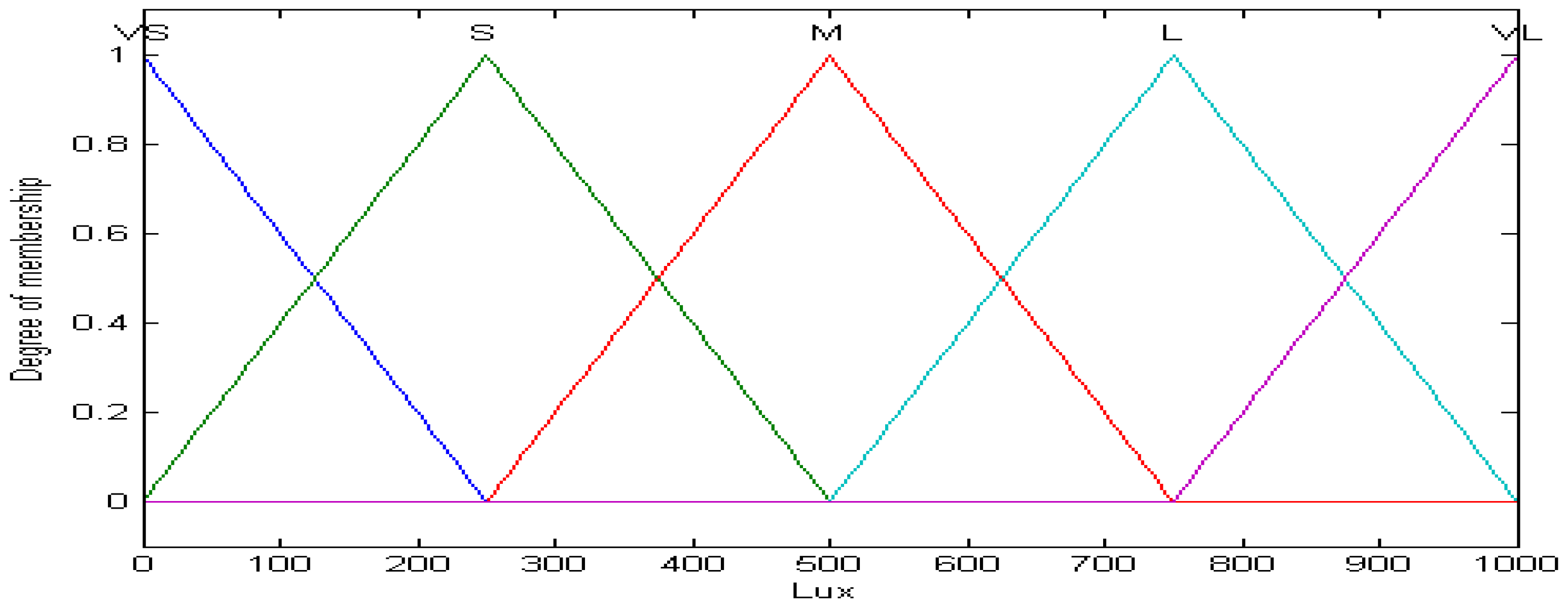
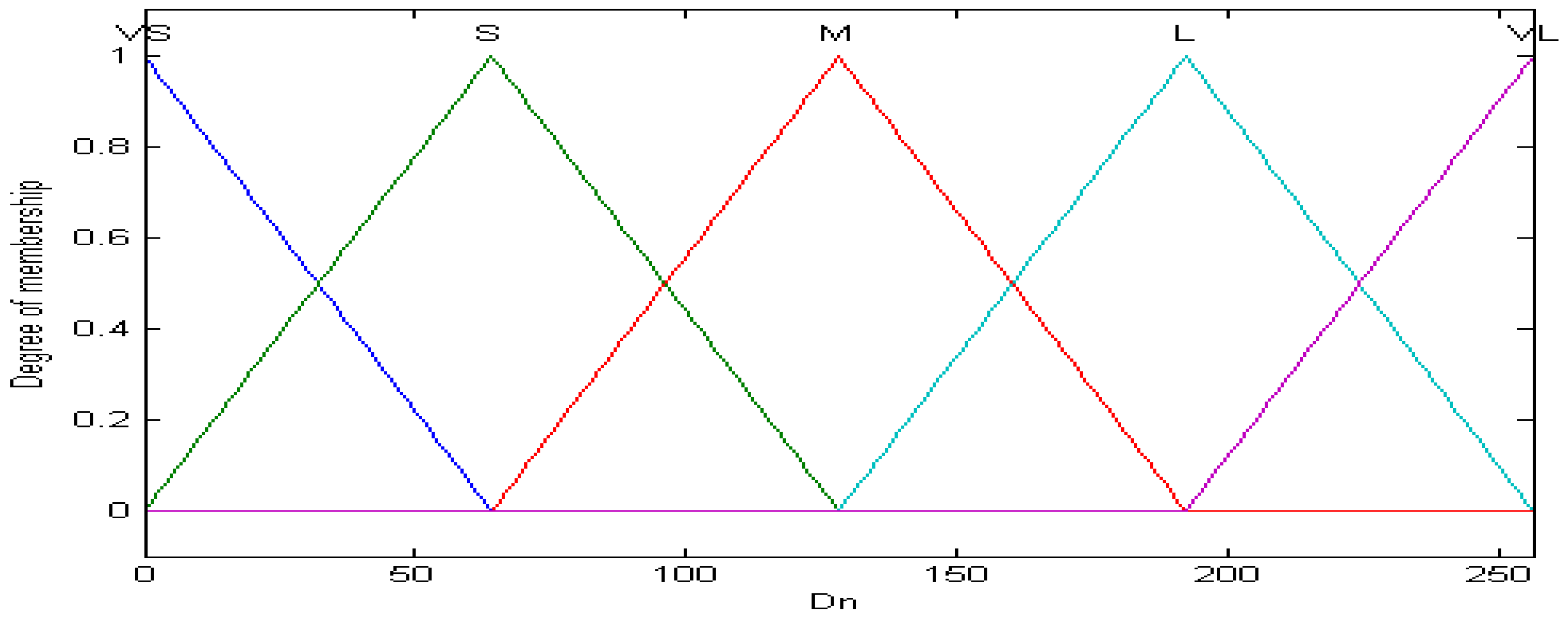
The original input value to the fuzzy controller was the explicit output from the ambient light sensor circuit. Therefore, we had to first fuzzicate this explicit value through a membership function in order to comply with the rules of fuzzy theory. In this work, the membership functions of the input of the fuzzy controller were categorized into five subsets (very small (VS), small (S), medium (M), large (L), very large (VL)) by the ambient light luminance ranging from 0 to 1000 Lux. On the other hand, the output from the fuzzy controller was set to be the MCP41010 variable resistance (Dn) of the photosensitive resistor divider. Its membership functions were also divided into five subsets by the same principle with a value ranging from 0 to 255. Figure 8 is the membership function for the ambient light luminance (Lux) and Figure 9 is for the MCP41010 variable resistance (Dn).
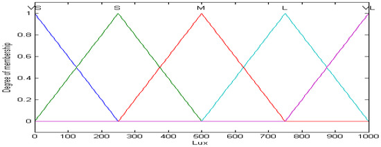
Figure 8.
Membership functions of Lux.
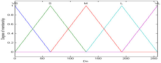
Figure 9.
Membership functions of .
3.2.2. Fuzzication Rules and Logical Design
Fuzzy logic theory can utilize experts’ knowledge and experience to formulate control rules of the controlled system. IF-THEN language is usually used to describe fuzzy rules. Fuzzy rules describe the relation between the input and output of the system. In general, fuzzy control rules can be described as follows:
In Formula (6), A and B are linguistic variables in membership function, x is the input variable and y is the output variable; their corresponding membership functions are defined by and .
Fuzzy inference: through calculation of the system’s fuzzy logic, combined with the fuzzy inference engine of all IF-THEN rules in fuzzy rule base, a reasonable system’s fuzzy output value is decided. There are many common fuzzy inference methods, including Product Inference Engine and Minimum Inference Engine. The fuzzy inference engine in this paper is the minimum inference engine, and its definition is as follows:
Depending on the variance in ambient light intensity (Lux) and adopting adequate digital variable resistance (Dn), we defined five general rules in the fuzzication database. The rules are as follows:
- (1)
- IF(Lux is VS) THEN(Dn is VL)
- (2)
- IF(Lux is S) THEN(Dn is L)
- (3)
- IF(Lux is M) THEN(Dn is M)
- (4)
- IF(Lux is L) THEN(Dn is S)
- (5)
- IF(Lux is VL) THEN(Dn is VS)
3.2.3. Defuzzication Design
After fuzzication, defuzzication is the next step to convert the results back to explicit values for further application. In general, the commonly used defuzzication methods include Center of Gravity Defuzzification, Center of Sum Defuzzification and Middle of Maxima Defuzzification. In this work, the Distributed Gravity Defuzzication is taken. As shown in Equation (8), the variables, n, yj, and indicate the quantization levels, the jth quantization value and membership value of yj in the fuzzy set (C). Furthermore, ycog is the output of the fuzzy controller.
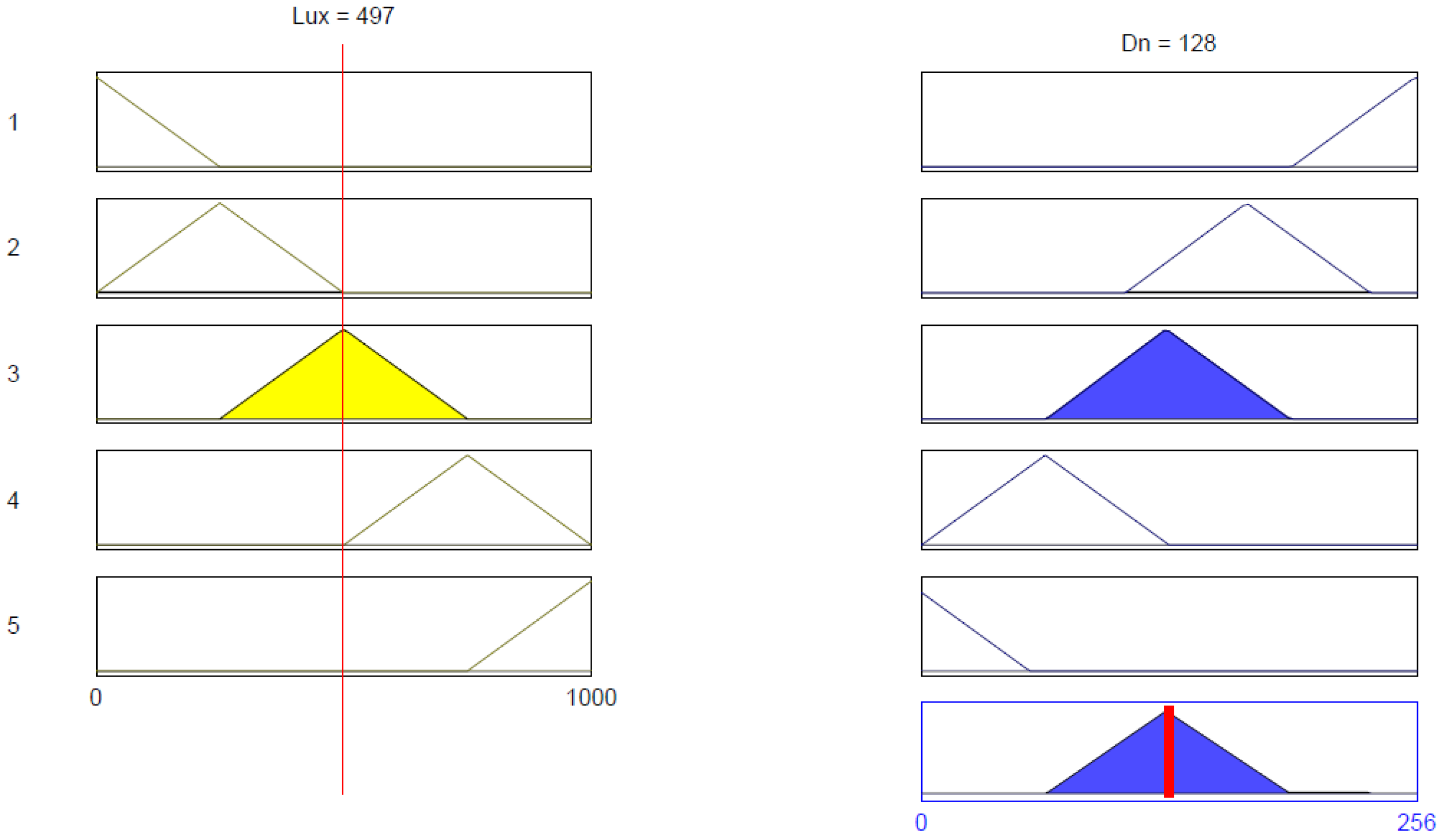
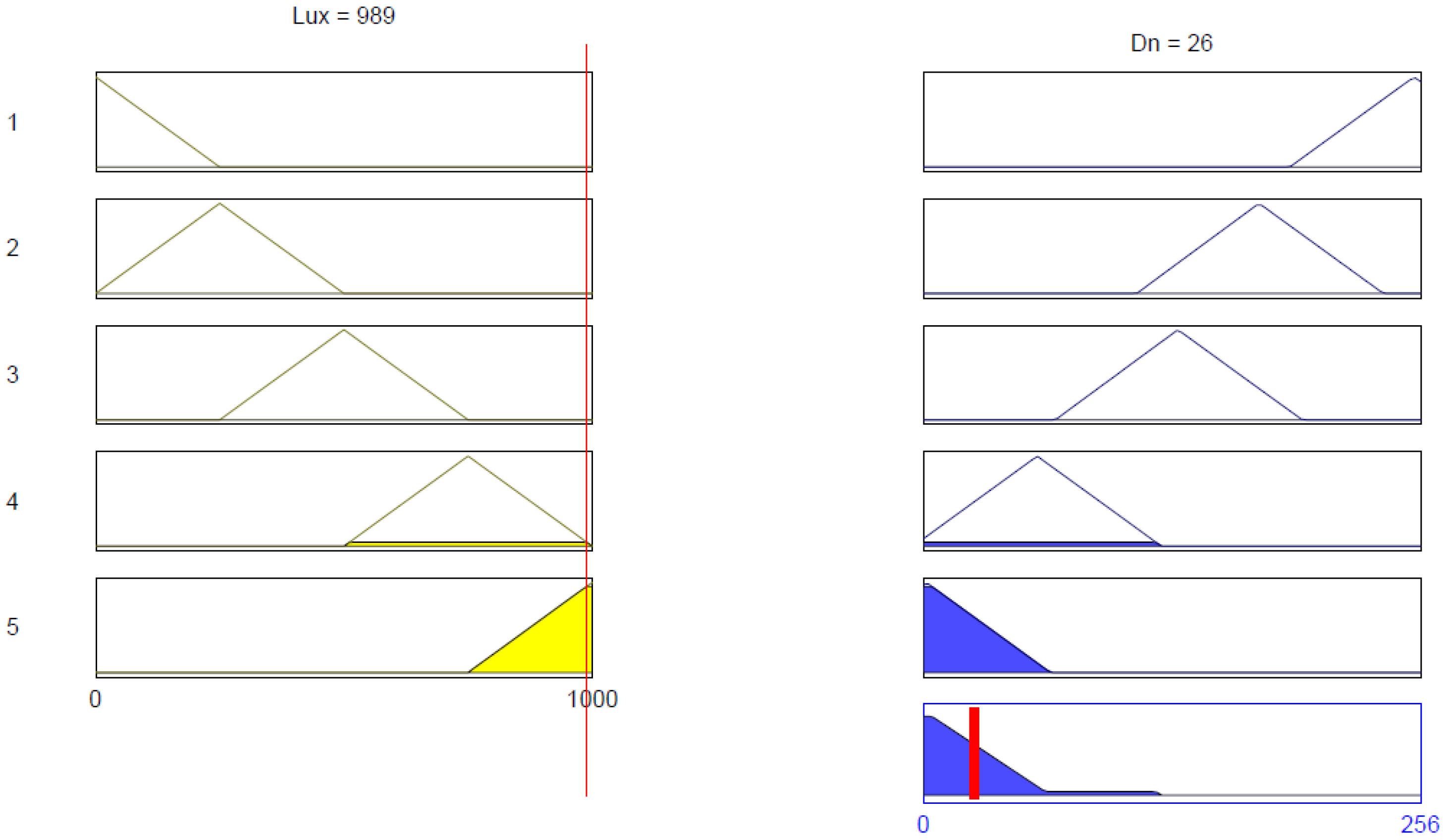
Figure 10 and Figure 11 are two trialing results generated by our model. Here, = 5 kΩ when the ambient light intensity is 497 Lux and the digital variable resistance = 128; while = 1.015 kΩ when ambient light intensity is 989 Lux and the digital variable resistance = 26. Table 3 shows some data of and Lux obtained in our experiments.
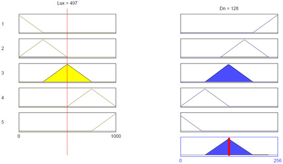
Figure 10.
When Lux is 497 Lux, is 128.
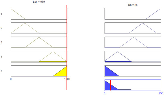
Figure 11.
When Lux is 989 Lux, Dn is 26.
Table 3.
and Lux.
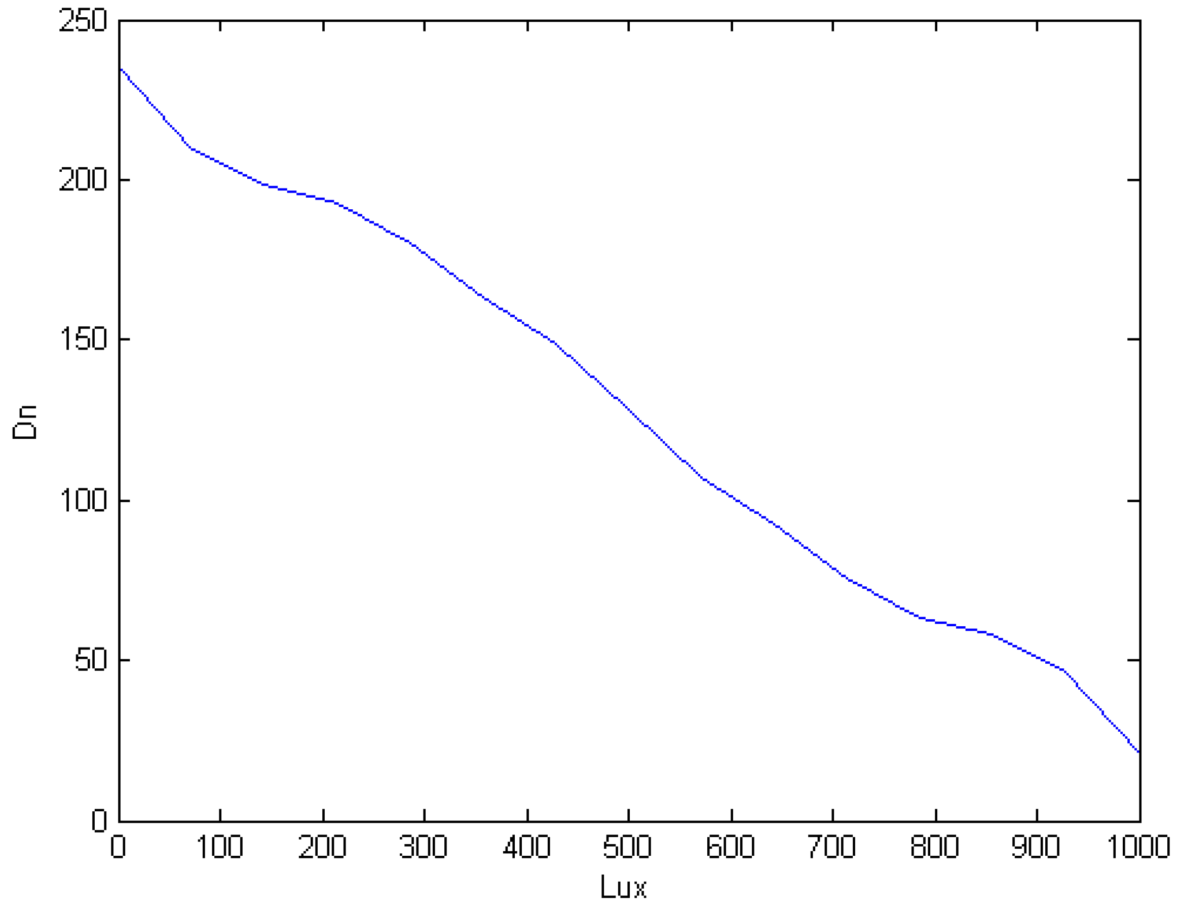
Figure 12 illustrates the characteristic curves of fuzzy controller inputs and outputs after fuzzication. To simplify programming on microcontrollers, we further divided the curve into seven domains. The equation for each domain is listed below: (here, m = slope, Luxn = ambient light intensity, Lux0 = initial ambient light intensity, Dn0 = initial value of the digital variable resistance).
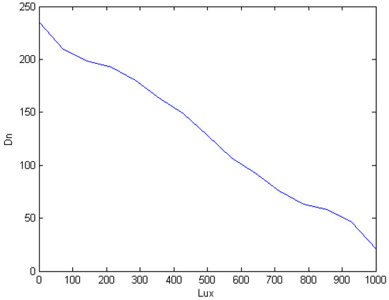
Figure 12.
Lux vs. .
3.3. Cloud Monitoring System
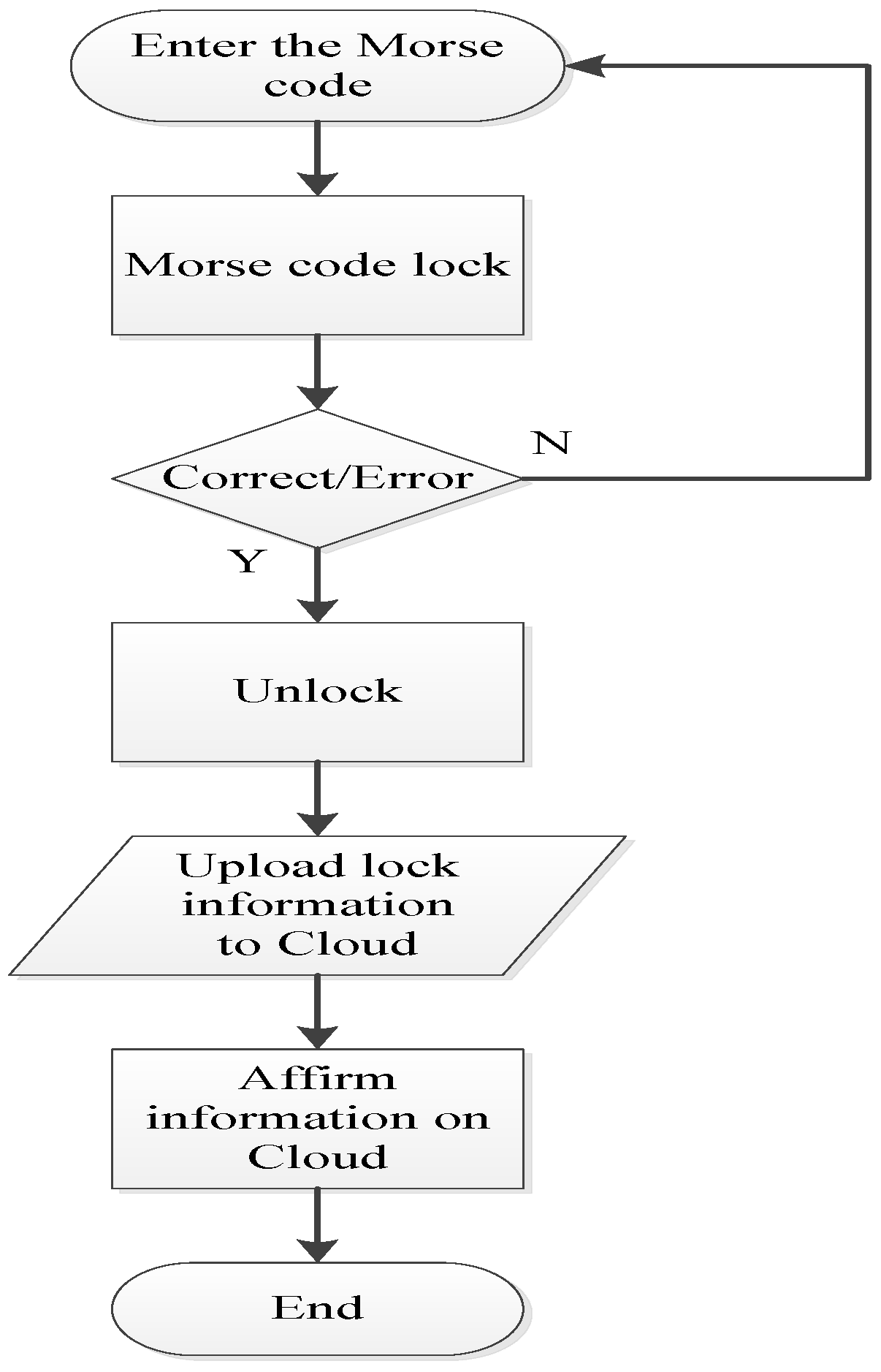
To build our cloud monitoring system, we have developed a remote mobile Morse code app under Android Studio. Figure 13 is a simplified flow chart on how the app works. It starts to compare signal input as soon as the user keys in the password. If the codes match, the user’s command will be encrypted and then sent to the receiving end. If it is incorrect, the user could reset the process by clicking “Clear”. The Morse code app user interface is shown in Figure 14.
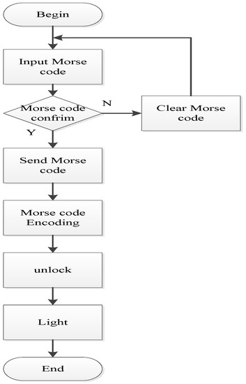
Figure 13.
Flowchart for our mobile Morse code app.
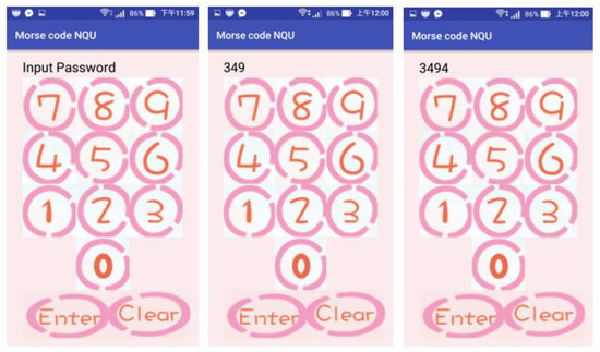
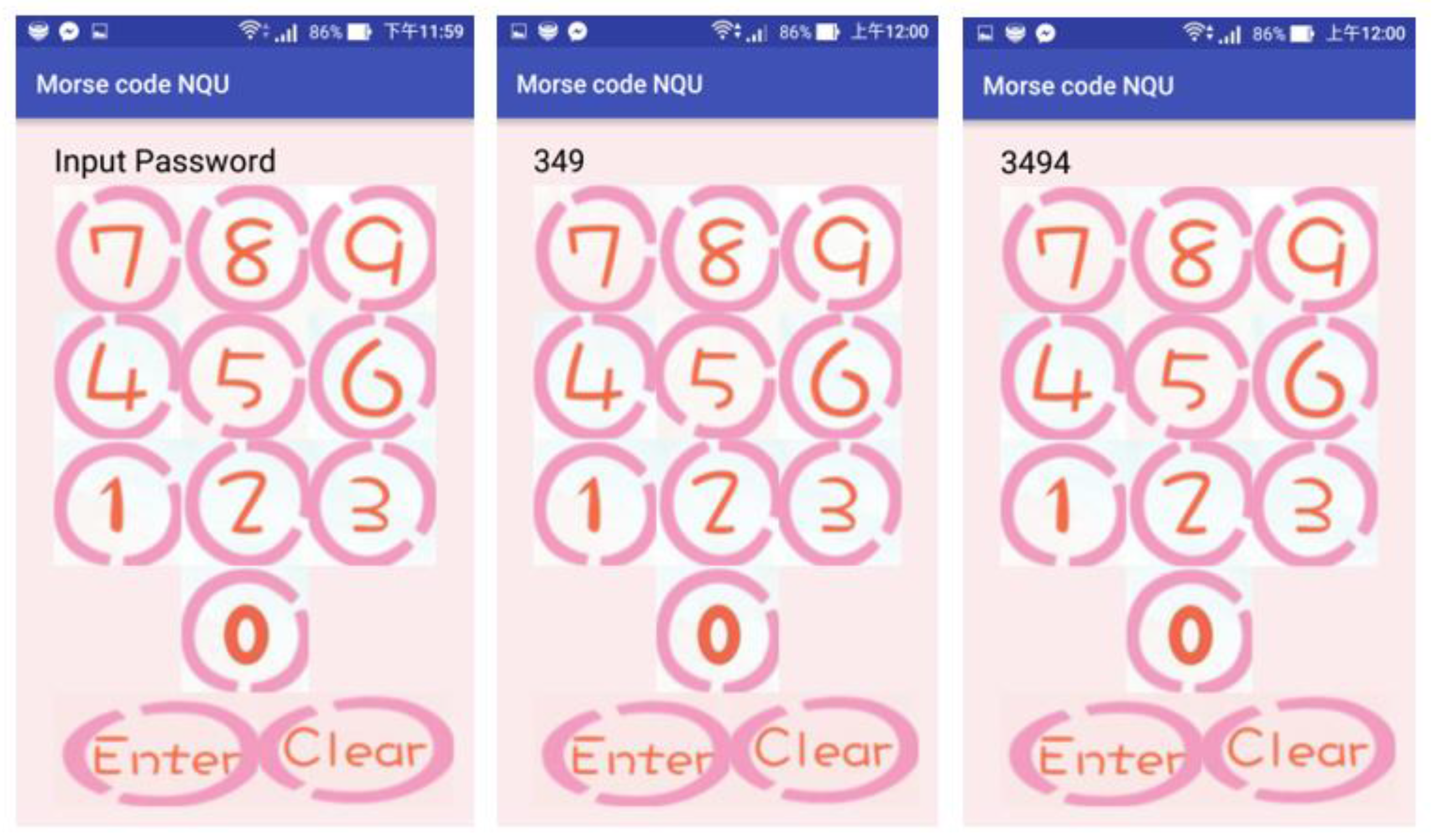
Figure 14.
The Morse code app user interface.
The biggest challenge and the main focus of this research is the interchanges between the binary optical signals (light on and light off) and the five statuses in the Morse code system. As seen below, the written program is available in our work and Figure 15 is the flow chart for encoding/decoding and cloud monitoring. To make it easier, we define “light off” as “0” (i.e., low level) and “light on” as “1” (i.e., high level) in our optical Morse code-based encoding/decoding program. The time interval of 0.1 s corresponds to dot and 0.3 s corresponds to dash respectively. On the other hand, a similar concept is used to indicate pauses between dashes and dots, two letters, or the end of Morse codes. Please refer to the following pseudo-code for more information on the logic of judgment.

Figure 15.
Flowchart for encoding/decoding and cloud monitoring.
Pseudo-code:
- READ pulse from photoresistor
- IF (pulse = peak)SET status = 1 //light onELSESET status = 0 //light off
- IF (status = 1)IF (time = 0.3 s)dashELSE IF (time = 0.1 s)dot
- IF (status = 0)IF (time = 0.02 s)Pulse between dash and dotELSE IF (time = 0.5 s)Pulse between lettersPRINT Morse code
- LOOP to 1.
4. Results and Discussion
4.1. Comparison between the Actual Ambient Light Intensity and the Measured Value
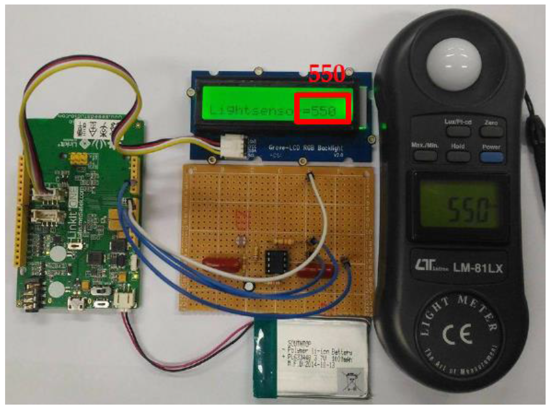
In Figure 16, we used photometer LM-81LX to test the reliability of our ambient light sensor under normal condition. We therefore proved that our model was highly reliable unless it was performed in an extremely dim environment, where negative deviation became increasingly significant.

Figure 16.
Ambient light sensor vs. photometer LM-81LX.
4.2. Experimental Results
The ambient light sensor and our proposed system were proven to be stable and reliable with multiple tests. The experimental results of Lux, , , were shown in Table 4. We discovered that in high ambient light intensity, and were smaller, and vice versa to stabilize the reference voltage (VB) of the photosensitive resistor divider.
Table 4.
Experimental results of and Lux.
4.3. Waveform Measurement of the Output Voltage VCE of Transistor 9013
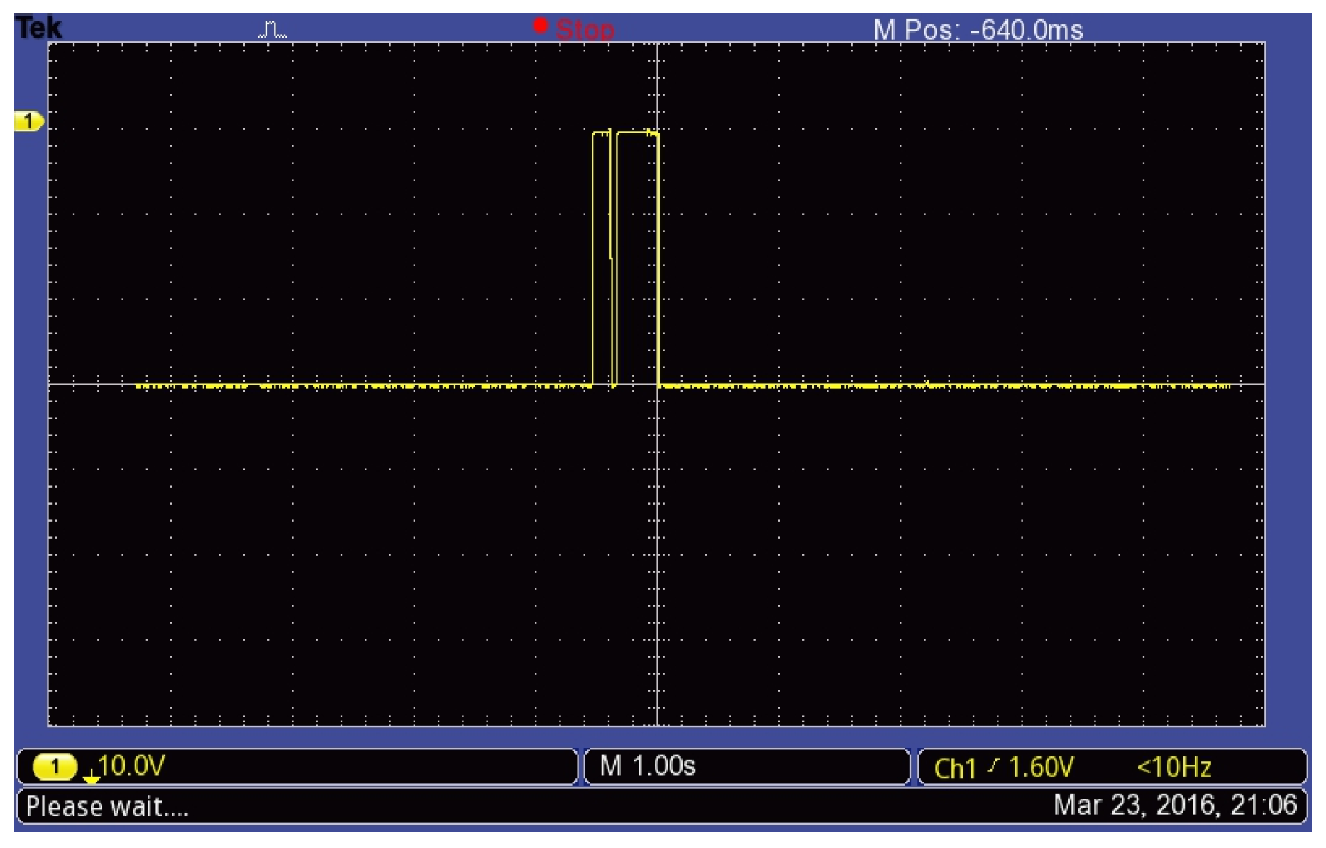
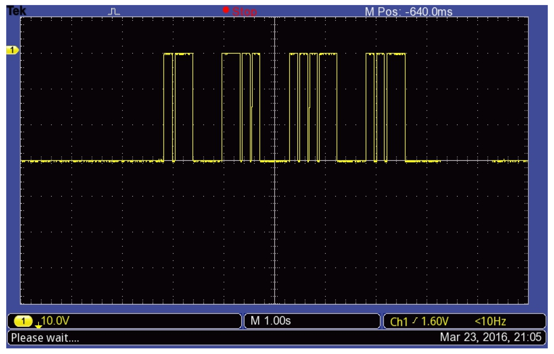
To prove whether the photosensitive resistor divider could faithfully translate flashlights into a corresponding Morse code, we measured the voltage difference (VCE) across the collector and emitter of 9013 using an oscilloscope. In Figure 17 and Figure 18, the voltage waveforms are magnified by ten-fold. We could see the obvious wide pulses and the other narrow pulses that represent “dashes” and “dots” respectively. Furthermore, both signals are correctly translated back to their original code, 1 and 1832, and then transmitted.
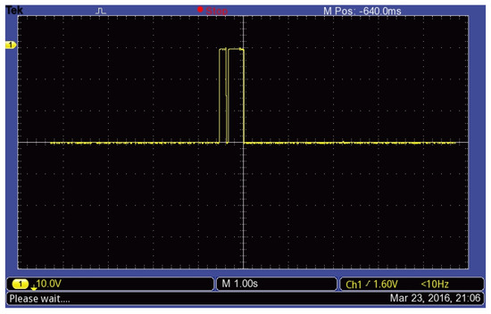
Figure 17.
Voltage waveform obtained by interpreting optical Morse code “1”.
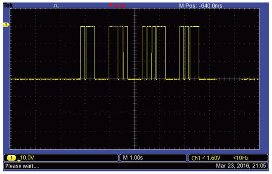
Figure 18.
Voltage waveform obtained by interpreting optical Morse code “1832”.
4.4. MCS Cloud Monitoring System
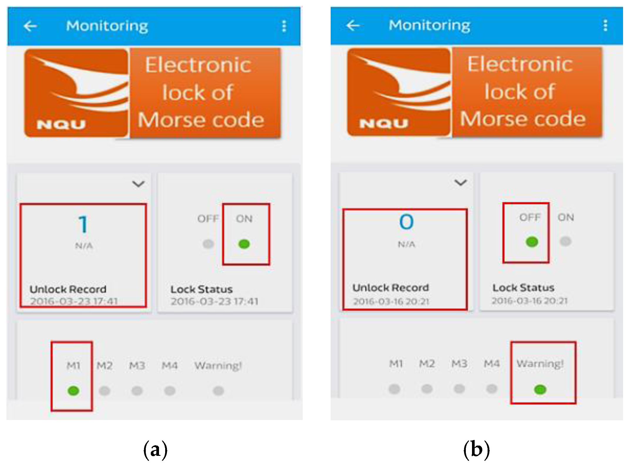
To evaluate the MCS cloud monitoring system, we tested it with correct and incorrect password inputs. In Figure 19a,b, it showed that the mobile app operated normally under either challenges. These experimental results match our expectations and prove the reliability and safety of our model. Apart from the “Lock Status” panel, the Arabic number indicates the identity of the transmitting end while the “Unlock Record” records the time point when an “open” instruction is made.
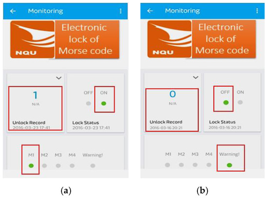
Figure 19.
Lock information on the cloud monitoring system (a) correct password inputs; (b) incorrect password inputs.
5. Conclusions
The Internet of Things is undoubtedly one of the most important technologies in the future of the electrons industry. For consumer electronics developers, cost and accessibility of the products are the key elements to success. In addition to pioneering by adopting the optical Morse code, fuzzy control theory and a digital potentiometer (MCP41010) were used to stabilize the reference voltage (VB) of the photosensitive resistor divider. The experimental results have shown that the correct performance rate of our novel electronic lock is 100%. Adding to the time strength of fast encryption, the novel system we designed is more competitive than other existing products for its relatively low price and convenience as it takes advantage of the universal use of smart phones as communication carriers and unlocking devices. It has the benefits of the fast encryption of Morse code, fast speed and high security of visible light transmission. As for the usage convenience and manufacturing cost, it is a relatively competitive choice. We are confident that the optical Morse code locking system proposed in this paper will possibly affect the application and development of the future smart lock with the prevalence of Li-Fi in the future.
In conclusion, it is worth noting that besides convenience and cost reduction, as a consumer electronics, our proposed system can be directly used with a user-friendly operation interface, and is therefore suitable for users of all ages.
Acknowledgments
This work was partially supported by National Quemoy University and Lee-Ming Institute of Technology.
Author Contributions
Chin-Tan Lee provided the idea, circuit design, measurement and experimental methods; Tung-Chun Shen performed the experiments; Win-Der Lee supported the results and wrote this paper.
Conflicts of Interest
The authors declare no conflict of interest.
References
- Sivaraman, V.; Dhamdhere, A.; Chen, H.; Kurusingal, A.; Grover, S. An experimental study of wireless connectivity and routing in ad hoc sensor networks for real-time soccer player monitoring. Ad Hoc Netw. 2013, 11, 798–817. [Google Scholar] [CrossRef]
- Lian, K.Y.; Hsiao, S.J.; Sung, W.T. Mobile monitoring and embedded control system for factory environment. Sensors 2013, 13, 17379–17413. [Google Scholar] [CrossRef] [PubMed]
- Huang, C.H.; Bai, Y.W.; Ren, J.H. Design and implementation of a door lock control based on a near field communication of a smartphone. In Proceedings of the 2015 IEEE International Conference on Consumer Electronics, Taipei, Taiwan, 6–8 June 2015; pp. 45–46.
- Sousa, P.J.; Tavares, R.; Abreu, P.; Quintas, M.; Reis, A.; Restivo, M.T. Wireless control and network management of door locks. In Proceedings of the 2015 3rd Experiment International Conference (exp.at’15), Ponta Delgada, Portugal, 2–4 June 2015; pp. 141–142.
- Tsonev, D.; Videv, S.; Haas, H. Light fidelity (Li-Fi): Towards all-optical networking. Proc. SPIE 2013. [Google Scholar] [CrossRef]
- Wang, Y.; Haas, H. Dynamic load balancing with handover in hybrid Li-Fi and Wi-Fi networks. J. Lightwave Technol. 2015, 33, 4671–4682. [Google Scholar] [CrossRef]
- Silva, S.; Valente, A.; Soares, S.; Reis, M.J.; Paiva, J.; Bartolomeu, P. Morse code translator using the Arduino platform: Crafting the future of microcontrollers. In Proceedings of the 2016 SAI Computing Conference (SAI), London, UK, 13–15 July 2016; pp. 675–680.
- Gaikwad, P.P.; Gabhane, J.P.; Golait, S.S. A survey based on smart homes system using Internet-of-Things. In Proceedings of the 2015 International Conference on Computation of Power, Energy Information and Commuincation (ICCPEIC), Chennai, India, 22–23 April 2015; pp. 330–335.
- Sung, W.T.; Hsu, C.C. IOT system environmental monitoring using IPSO weight factor estimation. Sens. Rev. 2013, 33, 246–256. [Google Scholar] [CrossRef]
- Mukherjee, K.; Chatterjee, D. Augmentative and alternative communication device based on eye-blink detection and conversion to Morse-code to aid paralyzed individuals. In Proceedings of the 2015 International Conference on Communication, Information & Computing Technology (ICCICT), Mumbai, India, 15–17 January 2015; pp. 1–5.
- Sapaico, L.R.; Sato, M. Analysis of vision-based text entry using Morse code generated by tongue gestures. In Proceedings of the 2011 4th International Conference on Human System Interactions (HSI), Yokohama, Japan, 19–21 May 2011; pp. 158–164.
- Hsieh, M.C.; Luo, C.H.; Mao, C.W. Unstable Morse code recognition with adaptive variable-ratio threshold prediction for physically disabled persons. IEEE Trans. Rehabil. Eng. 2000, 8, 405–413. [Google Scholar] [CrossRef] [PubMed]
- Yang, C.H.; Chuang, L.Y.; Yang, C.H.; Luo, C.H. Morse code application for wireless environmental control systems for severely disabled individuals. IEEE Trans. Neural Syst. Rehabil. Eng. 2003, 11, 463–469. [Google Scholar] [CrossRef] [PubMed]
- Jiang, J.; Zhou, Z.; Yin, E.; Yu, Y.; Liu, Y.; Hu, D. A novel Morse code-inspired method for multiclass motor imagery brain–computer interface (BCI) design. Comput. Biol. Med. 2015, 66, 11–19. [Google Scholar] [CrossRef] [PubMed]
- Yang, C.H. Adaptive Morse code communication system for severely disabled individuals. Med. Eng. Phys. 2000, 22, 59–66. [Google Scholar] [CrossRef]
- MediaTek Labs. Available online: http://labs.mediatek.com/site/global/developer_tools/mediatek_cloud/whatis_cloud/index.gsp (accessed on 5 August 2016).
- Chatterjee, A.; Sarkar, G.; Rakshit, A. A reinforcement-learning-based fuzzy compensator for a microcontroller-based frequency synthesizer/vector voltmeter. IEEE Trans. Instrum. Meas. 2011, 60, 3120–3127. [Google Scholar] [CrossRef]
- Lei, D.; Wang, T.; Cao, D.; Fei, J. Adaptive dynamic surface control of mems gyroscope sensor using fuzzy compensator. IEEE Access 2016, 4, 4148–4154. [Google Scholar] [CrossRef]
- Ma, Z.; Yan, L. Modeling fuzzy data with XML: A survey. Fuzzy Sets Syst. 2016, 301, 146–159. [Google Scholar] [CrossRef]
- Guo, K. Knowledge measure for Atanassov’s intuitionistic fuzzy sets. IEEE Trans. Fuzzy Syst. 2016, 24, 1072–1078. [Google Scholar] [CrossRef]
- LinkIt ONE-Seeed Studio. Available online: wiki.seeed.cc/LinkIt_ONE/ (accessed on 1 January 2017).
- Kumar, N.P.; Jatoth, R.K. Development of cloud based light intensity monitoring system using raspberry Pi. In Proceedings of the 2015 International Conference on Industrial Instrumentation and Control (ICIC), Pune, India, 28–30 May 2015; pp. 1356–1361.

© 2017 by the authors. Licensee MDPI, Basel, Switzerland. This article is an open access article distributed under the terms and conditions of the Creative Commons Attribution (CC BY) license ( http://creativecommons.org/licenses/by/4.0/).