Abstract
The variable displacement pump control system has greater energy-saving advantages and application prospects than the valve control system. However, the variable displacement pump control of differential cylinder is not concurrent with the existing technologies. The asymmetric pump-controlled cylinder is, therefore, used to balance the unequal volume flow through a single rod cylinder in closed-circuit system. This is considered to be an effective method. Nevertheless, the asymmetric axial piston pump (AAPP) is a constant displacement pump. In this study, variable-displacement asymmetric axial piston pump (VAPP) is investigated according to the same principle used in investigating AAPP. This study, therefore, aims at investigating the characteristics of VAPP. The variable-displacement output of VAPP is implemented by controlling the swash plate angle with angle feedback control circuit, which is composed of a servo proportional valve and an angular displacement sensor. The angular displacement sensor is connected to the swash plate. The simulation model of VAPP, which is set up through the ITI-SimulationX simulation platform, is used to predict VAPP’s characteristics. The purpose of implementing the experiment is to verify the theoretical results. Both the simulation and the experiment results demonstrated that the swash plate angle is controlled by a variable mechanism; when the swash plate angle increases, the flow of Port B and Port T increases while the response speed of Port B and Port T also accelerates. When the swash plate angle is constant, the flow of Port B and Port T increases along with the increase of pump speed, although the pressure-response speed of Port B is faster than that of Port T. Consequently, the flow pulsation of Port B and Port T tends to decrease gradually along with the increase of pump speed. When the pressure loaded on Port B equals to that of Port T, the flow ripple cycle of Port B is longer than that of Port T, whereas the peak flow of Port B is higher than that of Port T. Since the flow ripple of Port T is bigger than that of Port B, Port T should be connected to the low pressure sides or the oil tank so that it does not affect VAPP’s performance. Further, to avoid the backflow of VAPP from Port T to Port B, Port T cannot be loaded alone, and the loading pressure of Port T also cannot exceed that of Port B.
1. Introduction
Electro-hydraulic system is widely used in a number of factories and mobile machines such as excavators and cranes. Its hydraulic system has very high power density compared to electricity-operated systems and machine-drive systems. Electro-hydraulic systems can be divided into two major categories: valve-controlled systems and pump-controlled (displacement-controlled) systems. The former mode responds quickly, controls accurately, and its hydraulic system circuit is simple. Thus, it has widely been used in modern industry, machinery and equipment. The drawbacks of the valve-controlled system are: (1) a large percentage of power loss in the process of the measure flow going through the direction control valves; (2) throttling loss causes much heat loss, hence a cooling device is required, which increases the overall installation power and the cost of the system; (3) the oil source is easily polluted because of the open loop; and (4) its consumption of oil is high. Moreover, environmental pollution is anticipated to occur in the process of dealing with waste oil [1].
Compared with the valve-controlled system, the alternative circuit can considerably reduce or eliminate losses and provide significant energy saving. In 1994, Hewett patented a closed-circuit displacement control idea, wherein a two-position three-way valve is used to connect the charge line to the low-pressure side of a single rod cylinder when volumetric flow compensation is required [2]. A similar concept was independently proposed by researchers in British Columbia in 1995 [3]. Further, in 1998, a closed-circuit displacement-controlled actuation solution was proposed by Ivantysynova, in which a variable displacement pump controls the motion of a single or double-rod cylinder. This solution has since been developed by her team [4,5]. An open-circuit configuration may also be used for displacement control [6]. The pump-controlled system has higher energy efficiency and linear dynamic characteristics compared with the traditional valve control [7]. In 2012, Wang et al. presented a new scheme of a closed hydraulic circuit for a single rod cylinder. In this, the unequal flow rate is balanced through one of the pilot operated check valves to the low-pressure side whose pressure is close to the charge pump [8].
As mentioned above, the pump control system has great energy-saving advantages and application prospect, and has been improved in the way of symmetrical cylinder control. Nonetheless, for the single rod symmetrical cylinder, two hydraulic pump, or hydraulic transformer or hydraulic valve is used to exchange asymmetric flow. To reduce these inadequacies, Quan presented an asymmetric pump-controlled asymmetric cylinder strategy for balancing the unequal volumetric flow through a single rod cylinder in closed-circuit [9]. In 2013, Zhang et al. [10] developed a prototype of fixed displacement asymmetric axial piston pump (AAPP) with three suction/discharge ports in its rear case. The pump’s performances such as discharge pressure characteristics were investigated. The test result demonstrated that the volumetric efficiencies of AAPP were all more than 94.5% within the range of 21 MPa and were also equal to those of existing two-port pumps with the same displacement. Later, in 2014, the pumping dynamics of the fixed displacement AAPP were studied. The optimization of valve plate profile was carried out to reduce the amplitude of the pressure fluctuation and flow ripples. A fixed displacement pump prototype was manufactured and some qualitative tests conducted on the test rig [11]. Compared with the above methods, the asymmetric pump-controlled system has the advantage of small size, compact structure, low cost, kinetic, and potential energy recovery.
Accordingly, the displacement of AAPP [9,10,11] is constant. In this paper, variable-displacement asymmetric axial piston pump (VAPP) is studied on the same principle with AAPP [8,9,10,11].
2. Operation Principle of VAPP
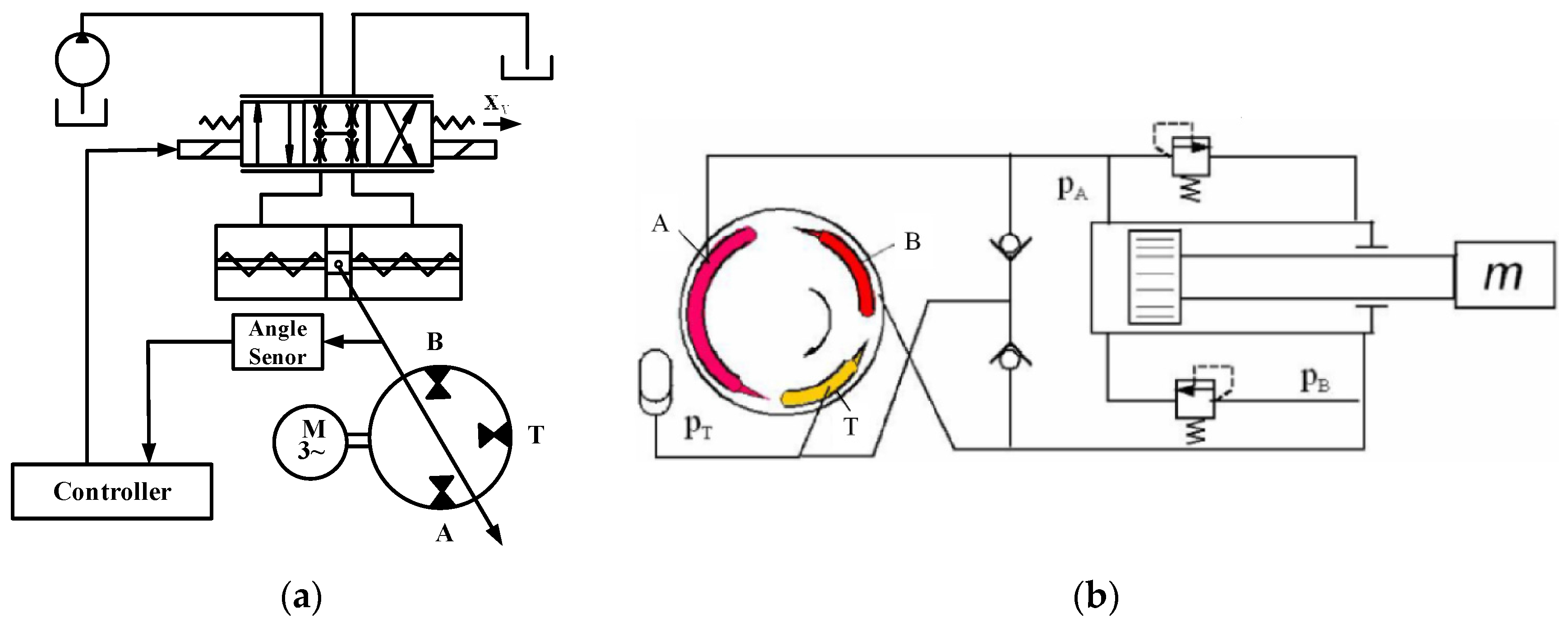
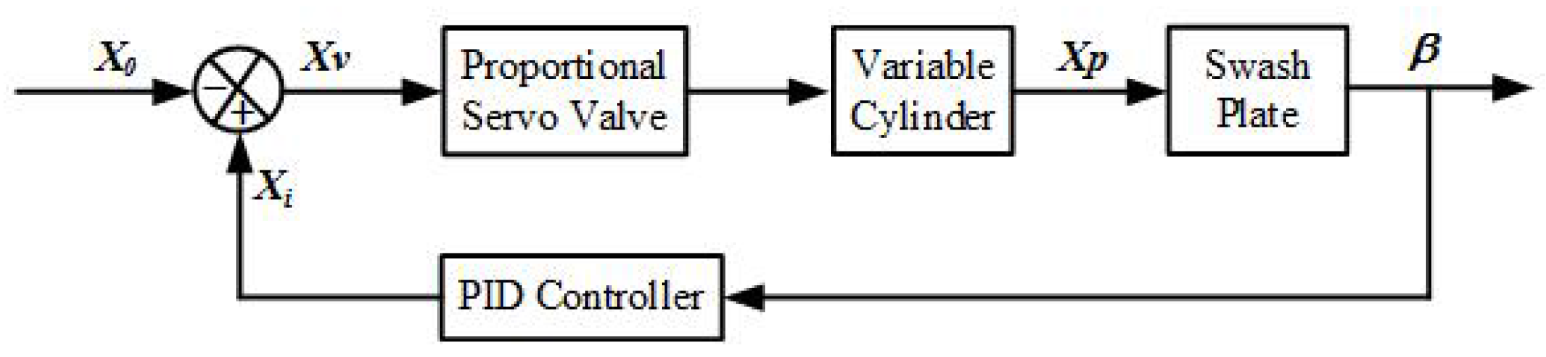
Considering variable control, the variable-displacement mechanism of VAPP includes manual control, mechanical control, electric control, hydraulic control and electro-hydraulic control for it to achieve displacement control, pressure control, flow control, power control and some composite control. As per the AAPP’s control differential cylinder hydraulic system requirements, the variable-displacement control unit is composed of a servo-proportional valve and symmetric hydraulic control cylinder (SHCC) (as shown in Figure 1a). The servo proportional valve and the angular displacement sensor, steadily connected with the swash plate, are used to compose the closed-loop control mode. By controlling the size and direction of swash plate angle of the asymmetric pump, the control of VAPP bi-directional variable displacement is attained. Thus, it meets the condition of quick dynamic response and optimal energy efficiency. Figure 1b illustrates the loop principle to control differential cylinder. In Figure 1, Port A, Port B and Port T are the inlet/outlet openings in the valve plate.
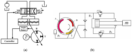
Figure 1.
(a) The principle of variable mechanism; and (b) the loop principle to control differential cylinder [10].
3. The Mathematical Model of VAPP
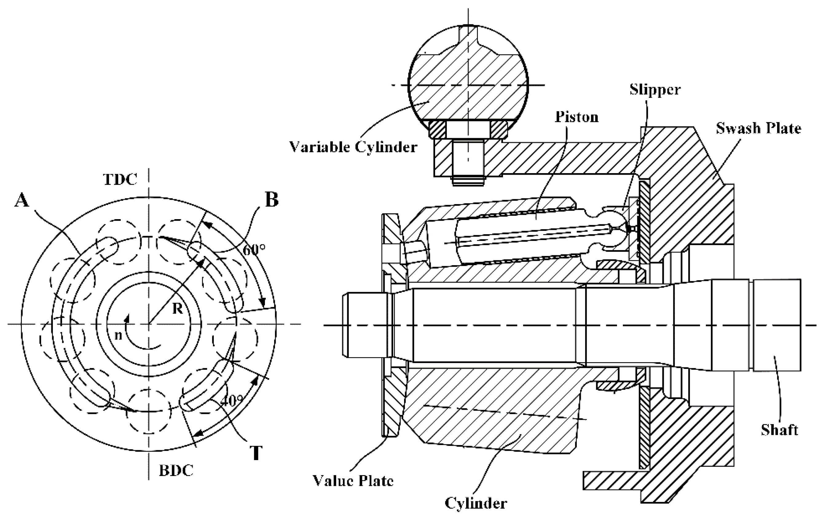
AAPP has 40 cc/rev geometric volume. The design parameters of the AAPP are shown in the literature [10]. The principle of variable-displacement asymmetric pump is indicated in Figure 2. VAPP uses a variable mechanism to adjust the swash plate angle in this way so that it can control the size and direction of displacement. By setting unidirectional unloading triangular tank in the distribution plate, VAPP can reduce the impact of pressure pulsation.
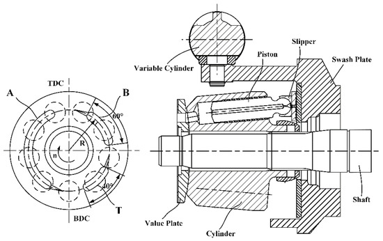
Figure 2.
The schematic diagram representing the variable-displacement asymmetric pump.
The angle β of the swash plate type VAPP is one of the key parameters of displacement control. In the variable mechanism, xi is the displacement of spool deviated from the zero location. When the solenoid receives a control signal, a proportional electromagnetic force acts on the spool and causes it to move against the return spring. Valve ports on both sides of the servo valve are open; high-pressure oil in the hydraulic system flows from the servo valve into the SHCC chamber. In this process, the piston rod moves x0, and makes the swash plate to rotate β0 degrees. At this time, the servo valve opening size is expressed as xv = x0 − xi. The hydraulic oil in the other chamber of the SHCC flows back to the tank through the other opening of the servo valve, and vice versa. Figure 3 shows the control relation diagram of the asymmetric pump variable mechanism.
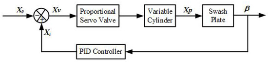
Figure 3.
The control relation diagram of the variable mechanism.
The connection between the displacement of piston rod xp and the rotated degree of swash plate β can be expressed as
In the equation, Ld is the force arm of the SHCC, which acts on the swash plate. Note VAPP rotation speed is n, and the number of pistons is z. Thus, the average theory flow is given by
where dk is the plunger diameter and R is the distribution circle radius of the plunger, β is the tilted degree of the swash plate, z is the number of pistons, and γ is the degree between the piston axis and the cylinder axis. Therefore, the instantaneous flow Qpi of ith piston is expressed as
where φi is the round angle of the ith cylinder, and ω is the rotational speed of the cylinder block.
For a VAPP with an odd number of pistons, if the conditions , and , are met, then the instantaneous output flow Qp of VAPP is given by
For the instantaneous cylinder pressure, pki with respect to the angular position of the cylinder block, φ, with φ = ω·t and dφ = ω·dt, is given by Reference [12,13]:
where pdi is the pump delivery pressure, pki is the instantaneous pressure of ith piston chamber, ρ is the density of oil, Cd is the flow discharge coefficient, Aop is the instantaneous discharge area of ith piston, Vo is the nominal volume of a piston chamber when the swash plate angle a is zero, and E is the oil bulk modulus which is affected by pressure and temperature [14].
When swash plate angle β was changed, the angular acceleration of the slipper relative to the cylinder is expressed as
The variable resistance torque, Md, needs to be overwhelmed for the symmetric hydraulic control cylinder to control the swash plate angle. Variable resistance torque Md-mainly includes torque Mh-acting on the swash plate by the hydraulic pressure through the piston, Mbf-friction resistance torque of spherical hinge, Mph-resistance torque (inertia force) of slipper component acting on the swash plate, Msf-sliding friction resistance torque of the swash plate, and Mif-inertia resistance torque of the swash plate itself. When Mif is ignored, the variable resistance torque is expressed as
where pd is the pump delivery pressure, α is the angle between piston hole, mps is the sum of the mass of piston and shoe, r is the radius of ball head, and f1 is the sliding friction coefficient between the swash plate and the shoe. f2 is the sliding friction coefficient between the ball head and the shoe. f2 = 0.08.
The variable resistance FLb controlling the swash plate angle is given by
The flow continuity equation for the variable cylinder is expressed as
Ctb is the total leakage coefficient of the variable cylinder which is equal to the sum of the internal and external leakage coefficients of the variable cylinder .
It is assumed that the oil in the variable system cannot be compressed while ignoring the leakage of the oil in the system. The dynamic equations of the variable system is, therefore, expressed as
where m is the mass of moving parts, Bp is the viscous damping coefficient, Ap is the effective area of piston, q is the flow in/out of hydraulic cylinder when load is driven, and Ksb is the spring stiffness loaded on the variable cylinder.
The total hydraulic spring stiffness Kh of the two chambers of the variable cylinder is the displacement function of the piston position. This can be given by the following equation
where V01 is the initial volume of oil entering the chamber in the variable cylinder, and V02 is the initial volume of oil taken back from the chamber in the variable cylinder.
When V01 = V02 or the piston locates in the middle position, Kh is the minimum. At this time, the variable cylinder has the lowest natural frequency and the stability of the system is the worst.
Variable system non-damping hydraulic natural frequency is given by
The damping ratio of variable system is expressed as
In the equation Kce = Kc + Ctb, Kce is the total flow-pressure coefficient of the system, whereas Kc is the flow-pressure coefficient which represents the change of flow caused by changed pressure.
4. The Simulation Analysis of VAPP
The simulation model of variable mechanism of asymmetric pump is shown in Figure 4. According to the above mathematical analyses, VAPP simulation model is built by the simulationX. In Figure 4, Port A is the inlet of the pump, while Ports B and T are the outlets. Conversely when Port A is the outlet, Ports B and T are the inlets. The flow ratio of A and B is 2:1, In this case, the pump can be used for driving asymmetric enforcement component. The model is composed of the variable mechanism and an asymmetric pump. The variable mechanism is composed of variable piston, variable spring, angle displacement sensor, servo proportional valve and a constant pressure source.
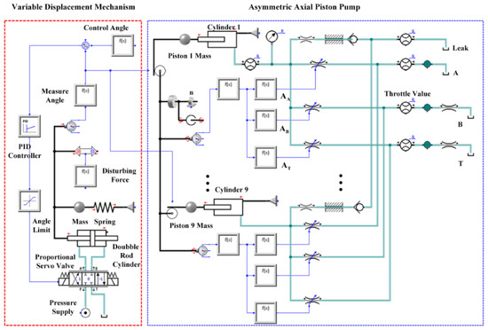
Figure 4.
The simulation analysis of VAPP.
The oil pushed by constant pressure source flows in SHCC through servo-proportional valves, and overcomes FLb, which is the resultant force of variable spring force, inertial force of variable spring force, inertial force of the swash plate and piston, and the disturbance torque. The oil pushes the variable piston and the swash plate articulated with it. Further, PID controls the flow of servo-proportional valves dependent on the difference valve on the control signal and the angular displacement sensors.
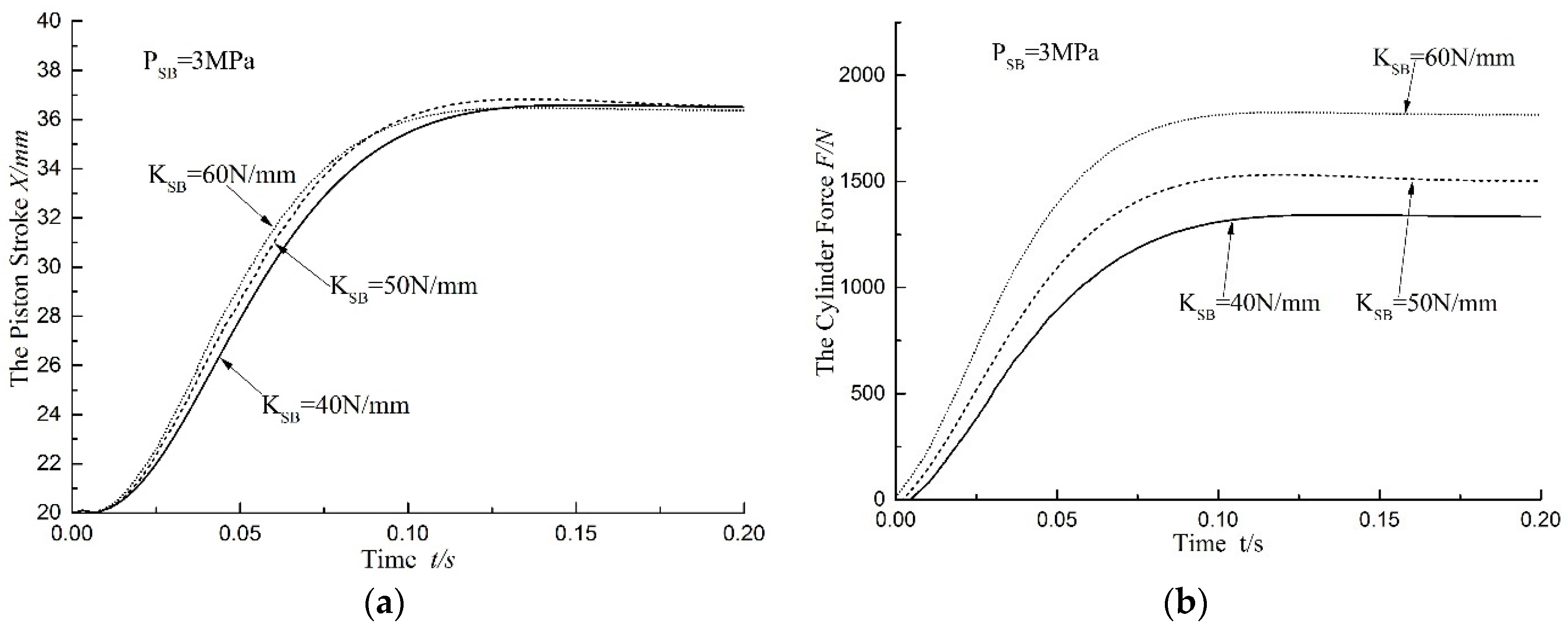
When the angle of swash plate in the simulation model of AAPP is set at 18°, and the pump speed, n, is 600 rpm, the pressure loaded on Ports B and T is 0 MPa while the oil supply pressure of variable mechanism Psb is 3 MPa and the friction resistance of variable mechanism is 600 N. Consequently, choosing stiffness of variable spring is 40 N/mm, 50 N/mm and 60 N/mm respectively, which regulates the PID value to produce overshoot of piston displacement consistent in those cases. The displacement and force of variable piston is clearly presented in Figure 5. The variable piston responses are shown to be quick and able to reach the maximum displacement first when the angle of swash plate increases from 0° to 18°, and the stiffness of spring Ksb is 60 N/mm. At this time, the variable force FLb is the maximum, at about 1750 N.
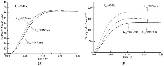
Figure 5.
The displacement and force of the variable piston: (a) the piston stroke, X; and (b) the cylinder force, F.
Similarly, when the angle of swash plate in the simulation model of AAPP is 18°, and the speed of the pump is 600 rpm, then pressure loaded on Ports B and T is 0 MPa, Ksb is 50 N/mm, and friction resistance of variable mechanism is 600 N. The supply oil pressures of the variable mechanism Psb are 3 MPa, 4 MPa and 5 MPa, respectively, regulating PID value to generate an overshoot of piston displacement consistent in those cases. The displacement and force of variable piston is shown in Figure 6, in which the angle of swash plate increases from 0° to 18°. The figure also illustrates that the variable piston responds quickly and reaches the maximum displacement first when oil supply pressure is 3 MPa. In order to avoid the mechanical impact of variable piston in the extreme position, it is needed to adjust PID parameter according to the change of parameter of variable mechanism.
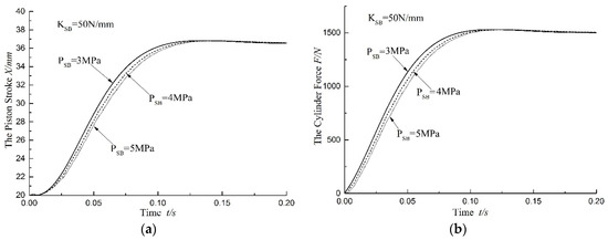
Figure 6.
The displacement and force of the variable piston: (a) the piston stroke, X; and (b) the cylinder force F.
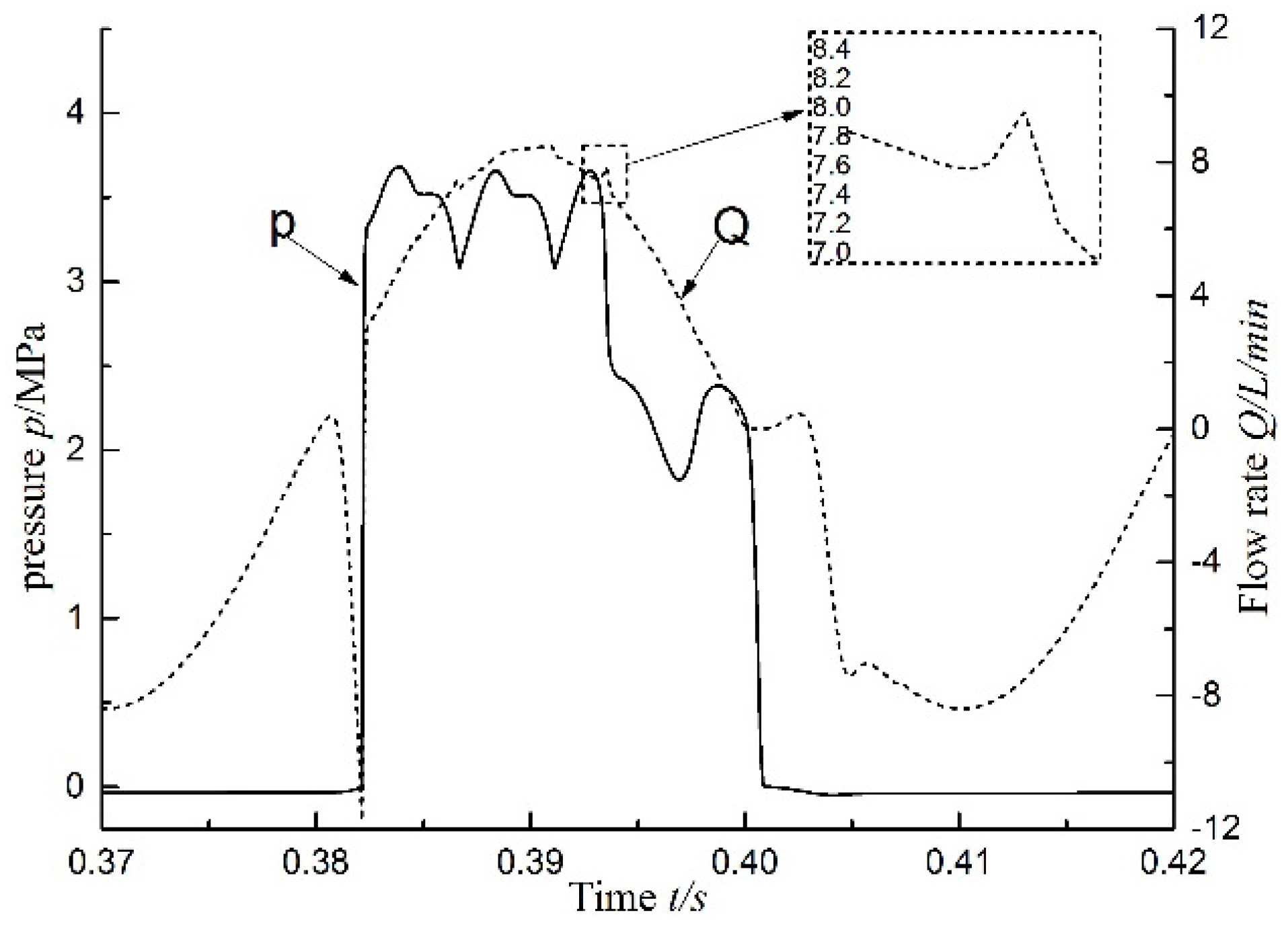
Equation (3) shows that the oil sucked and discharged by each piston chamber changes with the sine law. Conversely, Equation (5) indicates that the pressure of piston chamber is approximately equal to the atmospheric pressure during the suction phase, and was affected by the parameters Qpi, ω, Cd, ρ and E during the discharge oil phase. When VAPP speed is set at 1500 r/min and angle as 10°, and the pressure of Ports B and T relief valve are set at 0 MPa in the simulation model, then the pressure and the flow curve of one of the piston chambers is as depicted in Figure 7. The figure shows that the pressure of piston chamber remains constant at around 0 MPa from interval bottom dead center (BDC) to top dead center (TDC) in Port A. The pressure of Port A suddenly rises to about 6 MPa when piston passes TDC. It then reduces to about 4 MPa when piston passes the non-dead point triangular groove and reaches Port T. The pressure of piston chamber reduces to about 0 MPa periodically when piston passes Port B, Port T, BDC and reaches Port A. The reason for the above phenomenon is that the high pressure oil in the oil discharging port pours into piston chamber instantaneously when the piston filled with low pressure oil move from oil suction Port A to oil discharge port. Because the piston rotates constantly, the pressure in the piston chamber increases gradually. The piston begins to discharge oil when the pressure in the chamber is the same as the pressure in the oil discharging port. At this time, because of the inertia of the fluid and the damping effect of the distribution flow port, the resistance of discharged oil is high at the beginning while the pressure in the piston chamber exceeds the discharging pressure, thus becoming positive pressure overshoot. As the piston moves from the oil discharging port to the oil suction port, the high oil pressure port is connected with the low oil pressure port in the piston chamber. Therefore, pressure is released, therefore, pressure is released and therefore overshoots. This periodic change of the pressure and flow causes a periodic pulsation of the oil in the piston chamber.
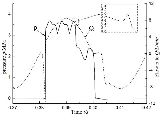
Figure 7.
Instantaneous cylinder pressure and flow without load at 1500 rpm.
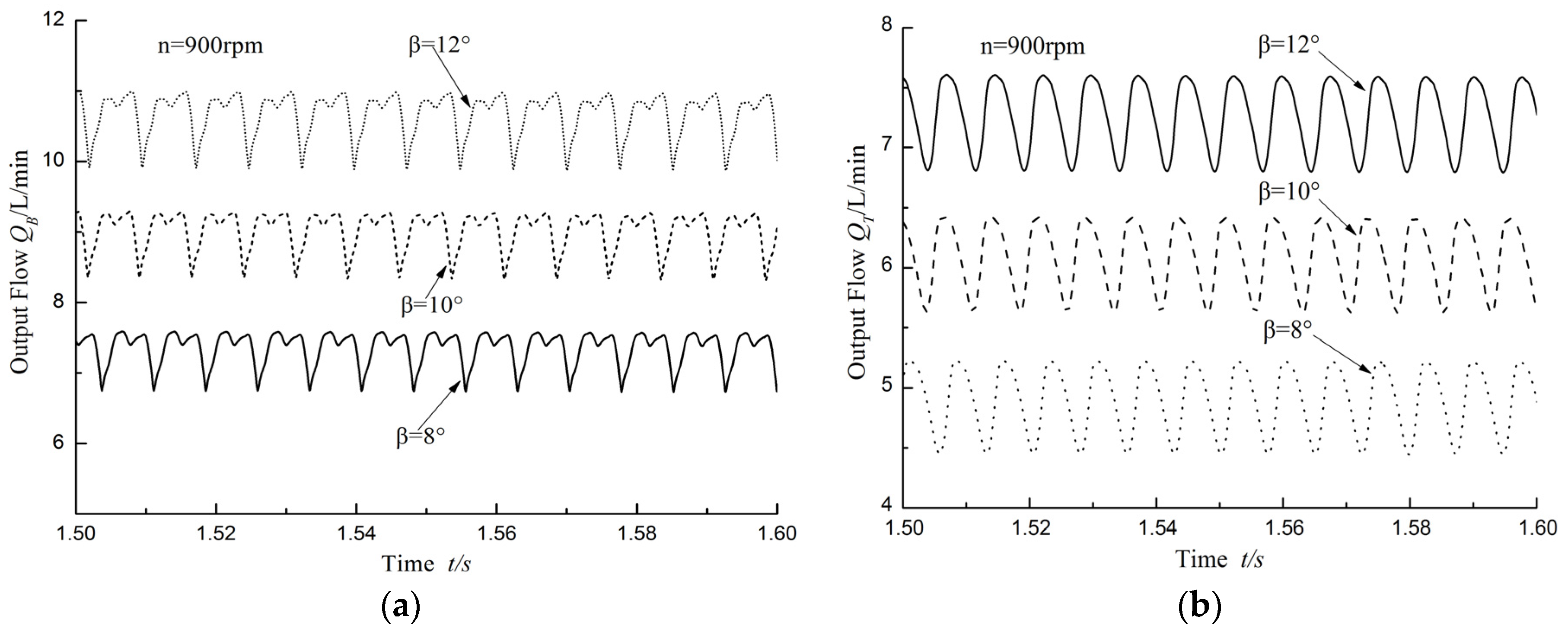
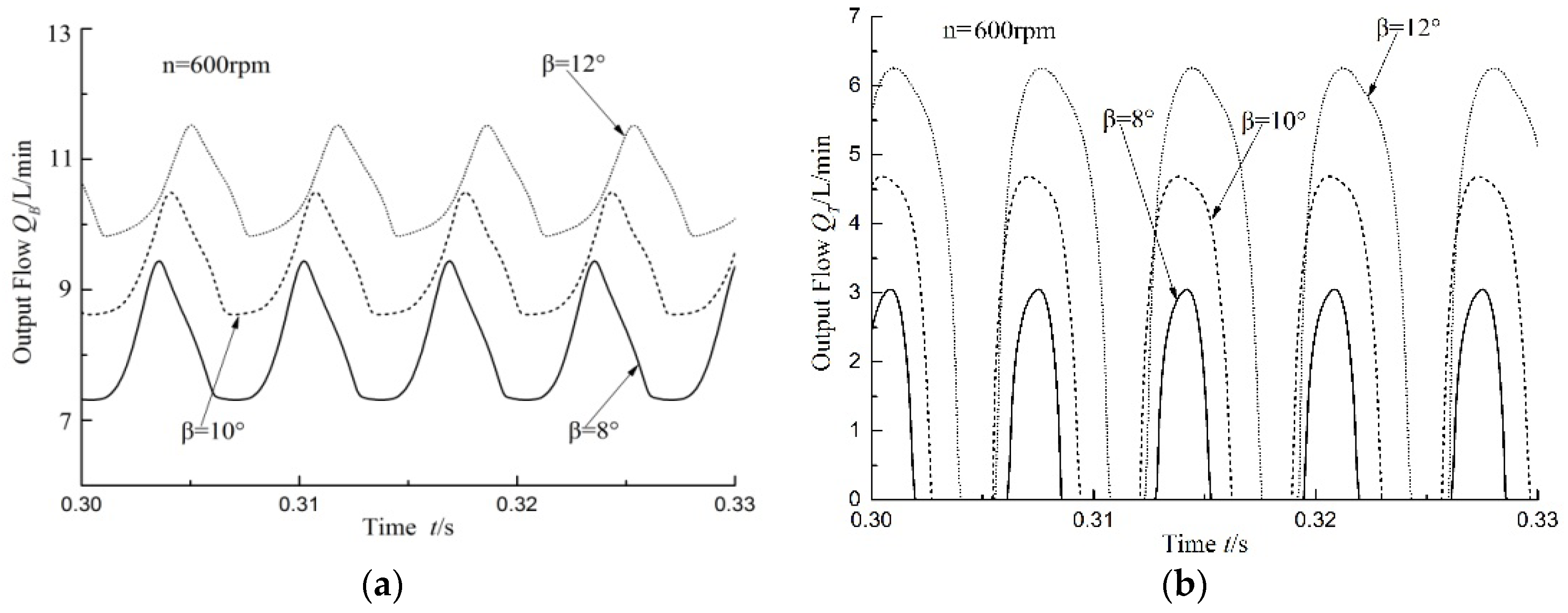
Piston speed is set at 900 r/min in the VAPP and the angle of the swash plate is 8°, 10° and 12°. Port A of the valve plate is for sucking oil, while Port B and Port T of the valve plate are for discharging oil. The flow of Ports B and T changes over time, as shown in Figure 8. The flow of Ports B and T increases along with the increase in the swash plate angle so that it could realize control of variable mechanism, as detailed in Figure 2. The angle of the indexing circle corresponding with Port B and T of valve plate is 60° and 40°, respectively. When the angle of swash plate is 12°, the flow of Port B is about 10.5 L/min while the flow of Port T is about 7.3 L/min. Since the indexing circle angle of Port B is bigger than that of Port T, the flow pulse period of Port B is longer than that of Port T. In addition, the flow crest of Port B is higher than that of Port T.

Figure 8.
Slots B and T output flow without load at 900 rpm: (a) Slots B output flow; and (b) Slots T output flow.
The angle of swash plate is set at 10° in the VAPP simulation model, pump speed at 600 rpm, 900 rpm and 1200 rpm, separately, and the pressure loaded on Ports B and T is 0 MPa. The flow of Port B and Port T changes over time, as shown in Figure 9. As detailed in Figure 9, when the swash plate angle is constant, the flow of Ports B and T increases along with the increase of pump speed and the flow pulsation decreasing along with the increase of pump speed. When the pump speed is 1200 r/min, the flow of Port B is about 11 L/min, whereas the flow of Port T is about 7.8 L/min.
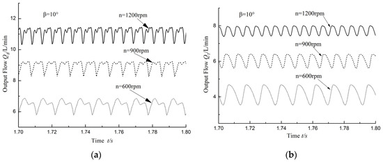
Figure 9.
Slots B and T output flow without load: (a) Slots B output flow; and (b) Slots T output flow.
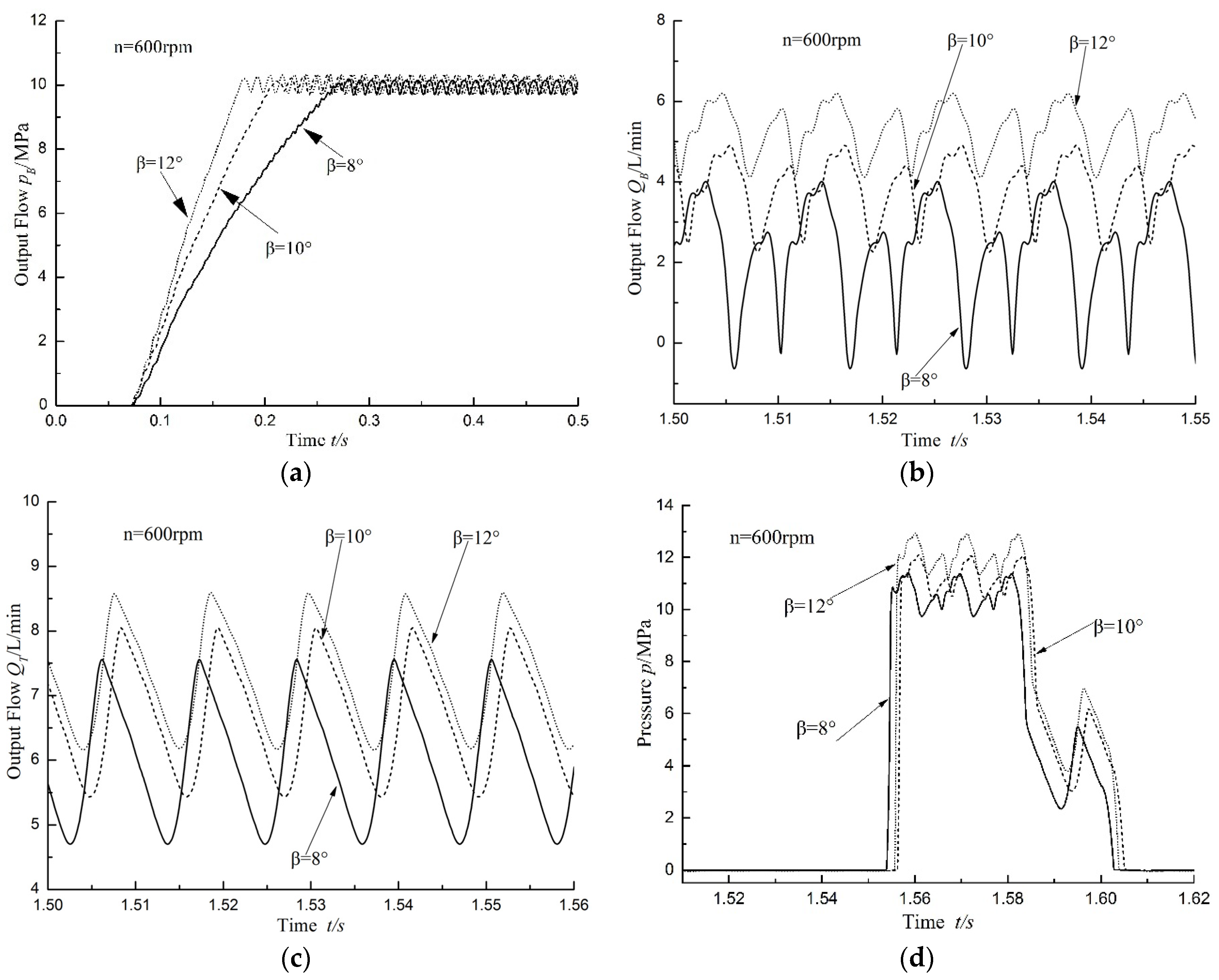
When the pump speed is set at 600 r/min, the angle of swash plate separately at 8°, 10° and 12°, and the pressure loaded on Ports B and T are 0 MPa and 10 MPa, separately, the flow of Ports B and T and the pressure of piston chamber are as indicated in Figure 10. It is observable from Figure 10a that the larger swash plate angle may make the pump to reach the set speed more quickly. In addition, it is evident from Figure 10a,c that the flow of Ports B and T increase along with the increase of swash plate angle. Since the working pressure of Port B was setting at 10 MPa, the flow pulsation decreases along with the increase of the swash plate angle, while the flow pulsation of Port T does not change significantly. It is evident from Figure 10d that although the working pressure of Port B is constant, the pressure of piston chamber increases along with the increase in the swash plate angle. When the swash plate angle is 8°, the maximum pressure of piston chamber is 11 MPa. However, when the swash plate angle is 12°, the maximum pressure of piston chamber is 13 MPa.
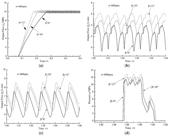
Figure 10.
Ten megapascals load in Slots B at 600 rpm: (a) Slots B output pressure; (b) Slots B output flow; (c) Slots T output flow; and (d) instantaneous cylinder pressure.
In the VAPP model, when the pump speed is set at 600 r/min, the angle of swash plate is 8°, 10° and 12°, separately, and the pressure loaded on Port B and Port T are 0 MPa and 10 MPa, respectively. Under these circumstances, the flow of Ports B and T is as shown in Figure 11. As evident in Figure 11a, the flow of Port B has flow pulsation of about 2 L/min when swash plate angle is 8°, 10° and 12°. As Figure 11b details, the flow of Port T changes in the periodic law, although there is an observed discontinuous flow. The reason for this phenomenon is that the pressure is loaded on Port T, thus the internal flow from Port T to Port B is increased. In the actual work of the pump, the phenomenon is not allowed. Therefore, Port T cannot be loaded alone or the pressure loaded on Port T cannot exceed the pressure which is loaded on Port B in the practical applications of VAPP.

Figure 11.
Ten megapascals load in Slots T at 600 rpm: (a) Slots B output flow; and (b) Slots T output flow.
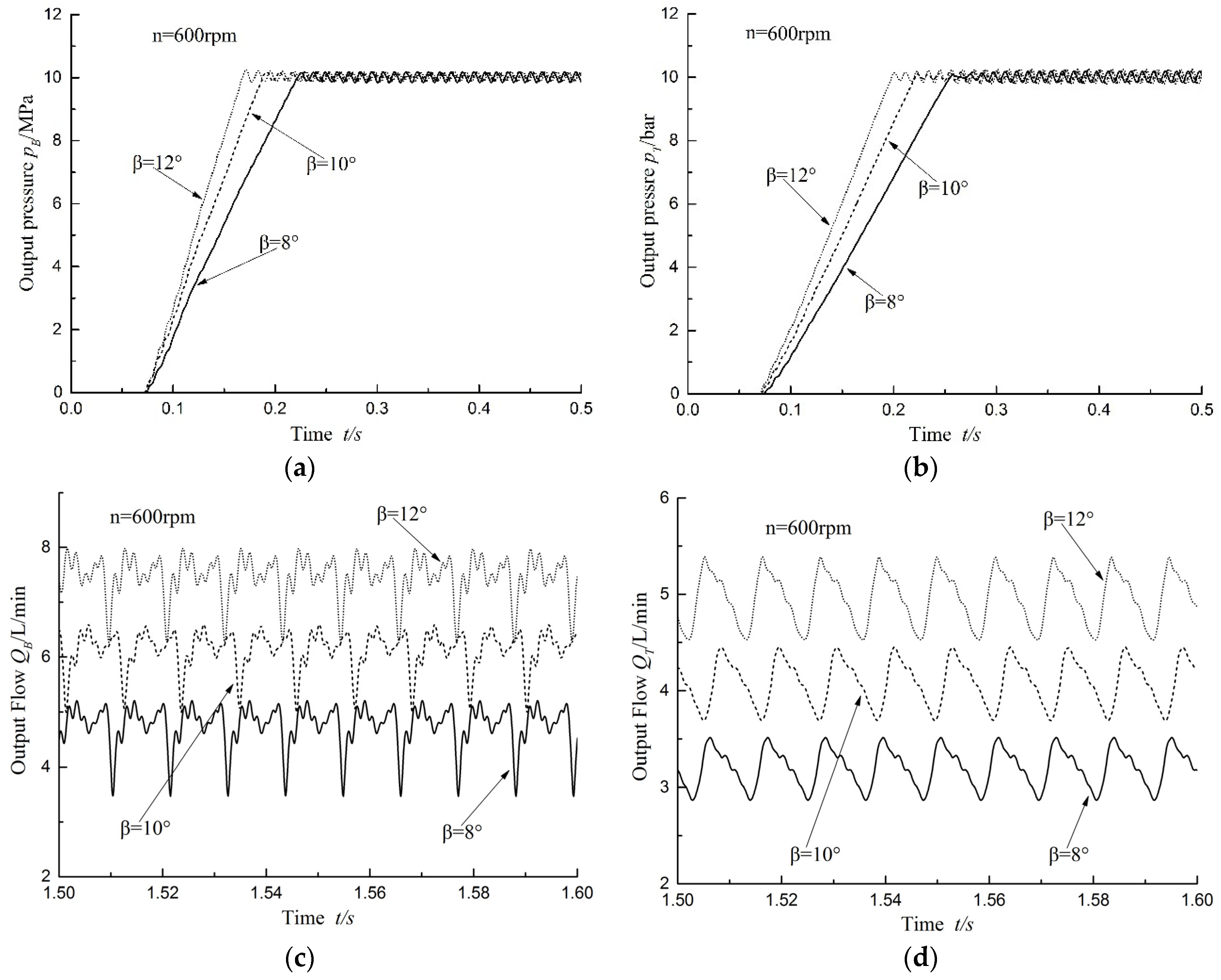
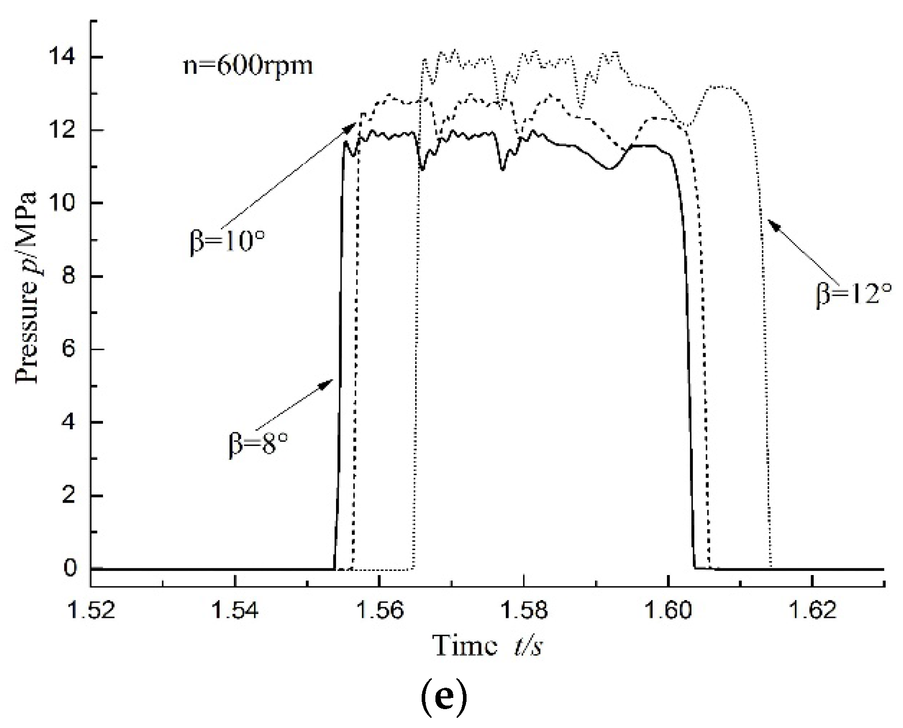
When the pump speed is set at 600 r/min, the angle of swash plate β is 8°, 10° and 12°, separately, and the pressure loaded on Ports B and T is 10 MPa. The pressure and flow of Port B, Port T and the piston chamber are as illustrated in Figure 12. As presented in Figure 12a,b, when the swash plate angle is big, the response of Port B and Port T is quick. Figure 10a and Figure 12c display that when the pressure loaded on Port T is constant, more pressure is loaded on Port B and the flow becomes less. By comparing Figure 8 and Figure 11, it can be deduced that when the pressure difference between B and T is great, the flow pulsation amplitude is large, and vice versa. The reason for this phenomenon is that the pressure difference between Port B and Port T is large. Therefore, the flow between Port B and Port T flow from the high-pressure area to the low-pressure area. It means that the flow would be stable if the pressure is loaded simultaneously on Port B and Port T of the VAPP. As illustrated in Figure 12e, when the swash plate angle is 12°, the pressure pulsation amplitude in the piston chamber is about 2 MPa. However, when the swash plate angle is 8° the pressure pulsation amplitude is 1 MPa. In conclusion, for VAPP, when two discharging ports are under the same pressure, the pressure pulsation of the piston chamber increases along with the increase in the swash plate angle.


Figure 12.
Ten megapascals load in Slots B and T, respectively at 600 rpm: (a) Slot B output pressure; (b) Slot T output pressure; (c) Slots B output flow; (d) Slots T output flow; and (e) instantaneous cylinder pressure.
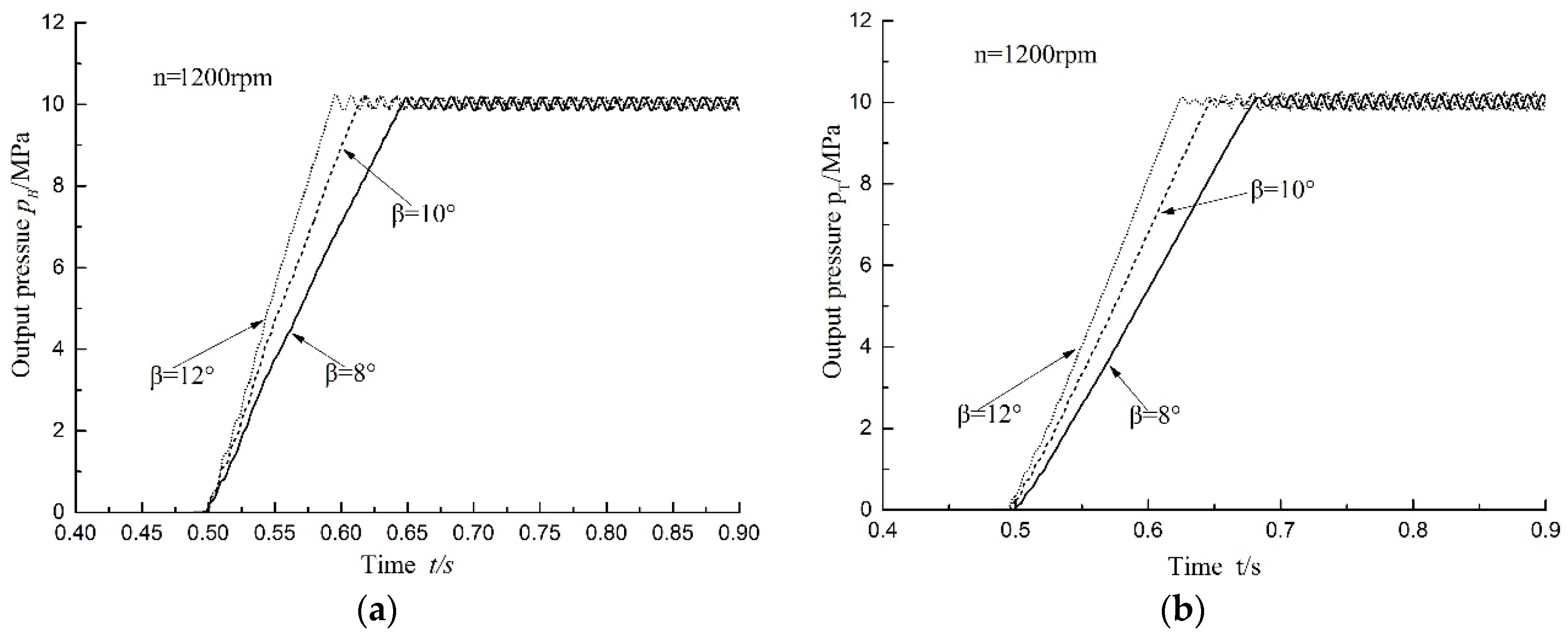
In the VAPP model, pump speed is set at 1200 r/min, the angle of swash plate β separately is 8°, 10° and 12°, and the pressure loaded on Ports B and Port T is 10 MPa. Under this working condition, the pressure change overtime of Port B and Port T is as displayed in Figure 13. As shown in Figure 13a, when β = 8°, the pressure gradient stabilization time of Port B and Port T is 140 ms and 170 ms, respectively. When β = 12°, the pressure gradient stabilization time of Port B and Port T is 80 ms and 120 ms, respectively. This indicates that the larger the angle of the swash plate is, the quicker the pressure response speed of the discharging port is. In addition, the system can reach a stable situation more quickly under the condition of even load. When the swash plate angle is constant, the response of Port B is quicker than for Port T.
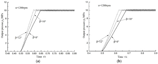
Figure 13.
Ten megapascals load in Slots B and T, respectively at 1200 rpm: (a) Port B output pressure; and (b) Port T output pressure.
5. The Verification Experiment of VAPP
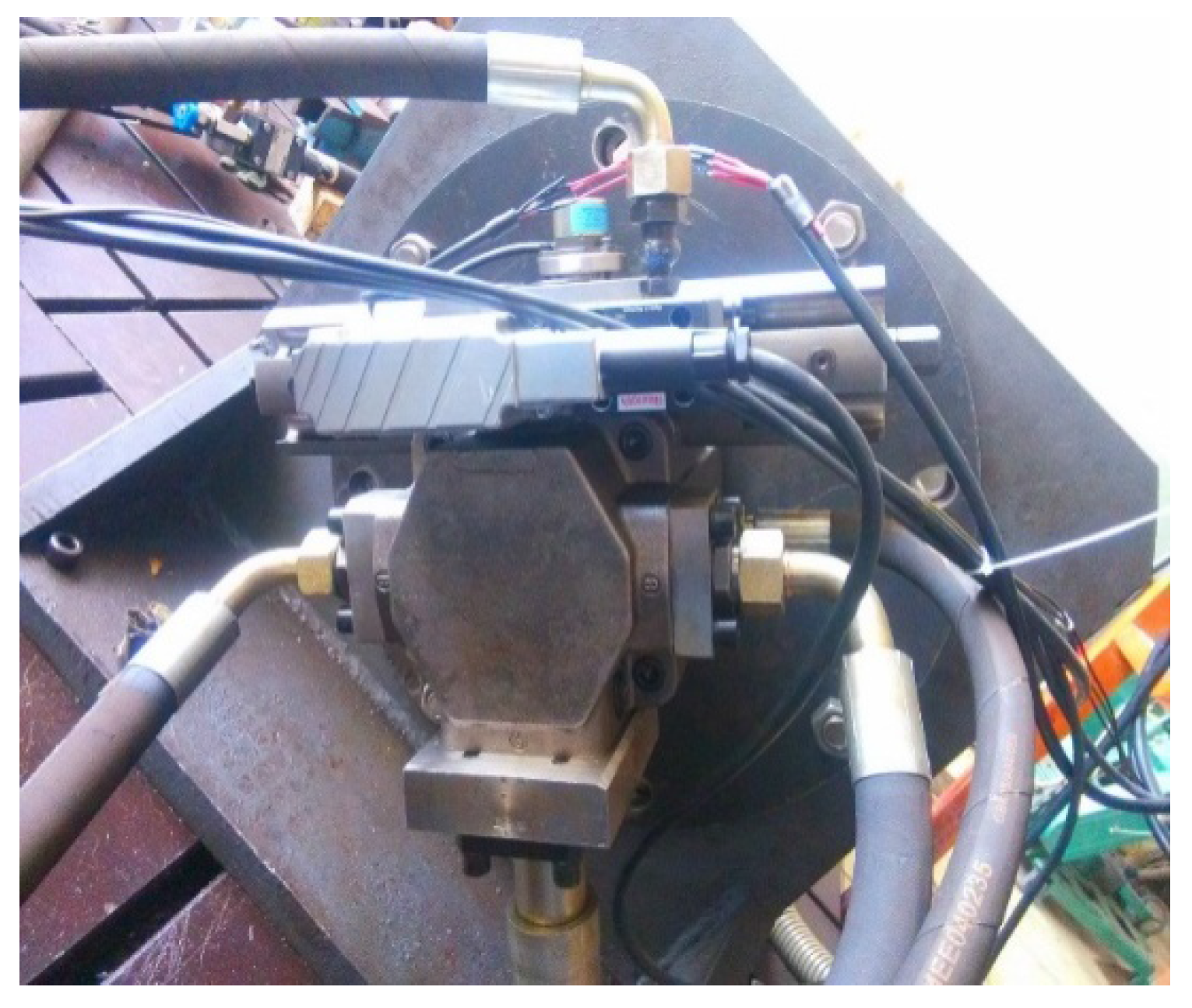
According to the controlling method of variable mechanism in Figure 2, the principle of characteristic test of VAPP variable displacement is shown in Figure 14. The variable displacement system of asymmetric pump controls the angle and direction of the swash plate by controlling the flow direction of oil and the opening area of servo-proportional valve. Thus, it can achieve accurate control of asymmetric pump displacement through setting the initial state of the swash plate at meso-position, or setting the swash plate angle at 0°. Pump 4 supplies oil for the left chamber when Valve 3 is in the left position. The swash plate articulated with the slider in the variable cylinder rotates clockwise in this process, as chamber sucks the oil but Port B and Port T discharge oil. When Valve 3 is in a meso-position, the two chambers of variable cylinders do not suck oil, and when the swash plate is in meso-position and A, B and T chambers do not discharge oil. When Valve 3 is in the right position, Pump 4 supplies oil to the right chamber, but this time, the swash plate rotates anticlockwise and Chambers B and T suck the oil, while Chamber A discharges the oil. Among them, dSpace can collect the angle signal of the swash plate and send accurate control signals to the servo-proportion valve. The loading on discharging Port B and Port T is realized by the relief valves. Figure 15 is the image of the VAPP that is used for the experiment, the physical photo of VAPP and test scene of VAPP can be found in Supplementary Materials. The angle displacement sensor, whose mode is MIDORI PRECISIONS CP-2UK-R260, is used for measuring the swash plate angle. The maximum input voltage of the sensor is 8 V, and it can detect the angle within ± 30 degrees. The servo proportion valve, model Rexroth 4WRPEH6C4B12L-20/G24K0/A1M, is used for controlling the angle of the swash plate. The maximum input flow of the servo proportion valve is 12 L. Further, the hydraulic flow meter, whose model is PARKERSCLV-PTQ-300, is used for measuring the flow and pressure of Port B and Port T. The maximum flow and pressure which can be measured by the hydraulic flow meter is 300 L/min and 42 MPa separately. The directly operating relief valve, model HUADE DBDS6P10B/315, is used for loading on Port B and Port T. The maximum set pressure of directly operating relief is 31.5 MPa.
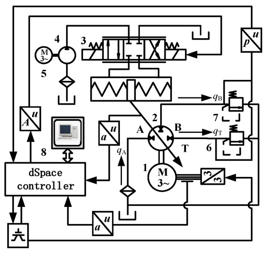
Figure 14.
The characteristic test principle of VAPP.
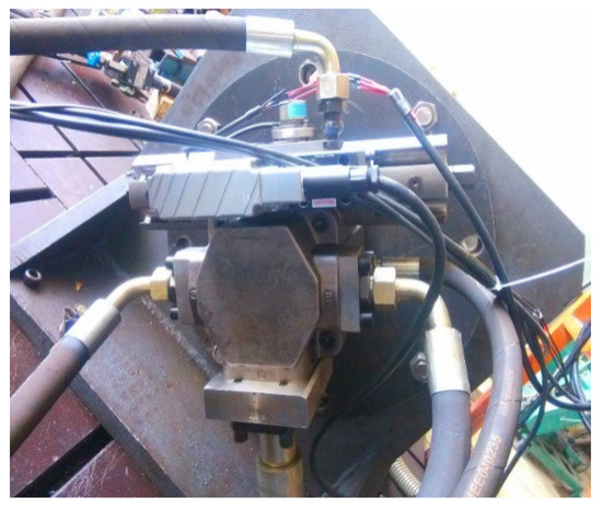
Figure 15.
The VAPP prototype image.
Asymmetric pump speed is set at 600 r/min and swash plate angle at 18°. Port B and Port T take 10 MPa and 20 MPa at two levels of pressure to load, respectively. The loading condition of the test includes two kinds: loading on Port B alone and loading on both Port B and Port T. Collecting the pressure signals of Ports B and T, respectively, in the experiment. The pressure of Port B under two different pressure levels is depicted in Figure 16a, when the pressure is loaded on Port B alone. As shown in the image, the results got from the simulation process are consistent with the results obtained from the experiment. The pressure pulsation of Port B increases along with the increase of pressure loaded on Port B. The total pulsation amplitude is still small, thus the system performance is good. The pressure of Ports B and T under four pressure levels is also shown in Figure 16b,c, in which the pressure is loaded on Ports B and T at the same time. As detailed in the figure, the results obtained from the simulation process are consistent with the results attained from the experiment. The working pressure of Ports B and T fluctuate periodically around the loading pressure, and the system performance is good. It can also be concluded that the pressure pulsation amplitude of Port T is slightly bigger than that of Port B. The pulsation amplitude of flow increases synchronously when loading of Ports B and T is equal. Figure 16d presents the test pressure of Port B when the port is loaded alone and when Port T and Port B are loaded at the same time. The two sets of curves are measured respectively at pressure levels of 10 MPa and 20 MPa. It can be deduced from Figure 16d that pulsation amplitude of pressure when Port B is loaded alone is bigger than the pulsation amplitude of pressure when Ports B and T are loaded at the same time. The pulsation amplitude of pressure when Port B is loaded alone is 1.5 times that of when both Port T and Port B are loaded at the same time and at the pressure level of 10 MPa. The pressure pulsation amplitude when Port B is loaded alone is 2.3 times that of when Ports T and B are loaded at the same time and pressure levels of 20 MPa.
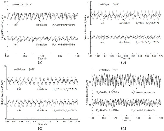
Figure 16.
The comparison of experiment and simulation. (a) Slot B output pressure under Ten and twenty megapascals load alone in Slots B; (b) Slot B output pressure under Ten and twenty megapascals load in Slots B and T at the same time; (c) Slot T output pressure under Ten and twenty megapascals load in Slots B and T at the same time; (d) Slot B output pressure under two different operating conditions and two pressure levels.
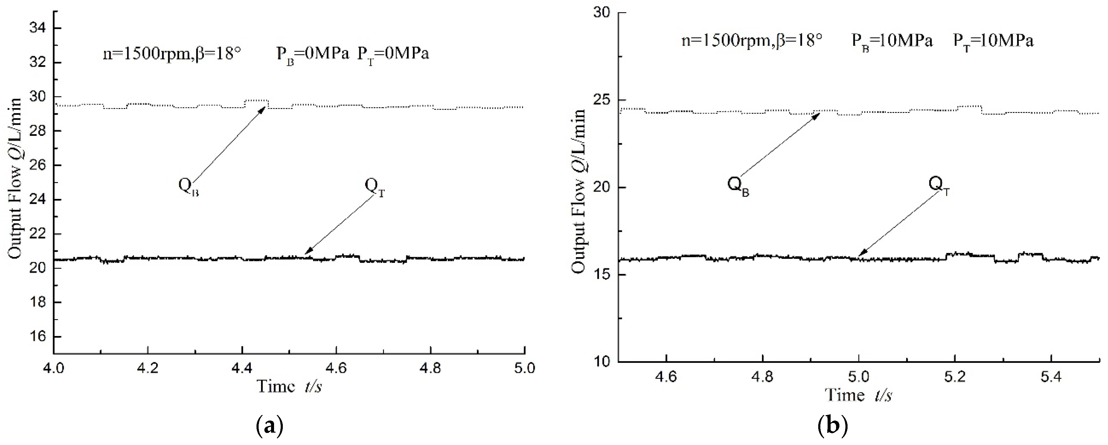
When the pump speed is set at 1500 r/min and swash plate angle is 18°, the flow test result is as illustrated in Figure 17. The no-load working condition of discharge Port B and Port T is presented in Figure 17a, whereas the working condition is indicated in Figure 17b, when discharging Port B and Port T are loaded at 10 MPa. As shown in the figure, the output flow of Ports B and T is 29 L/min and 20.5 L/min, respectively, when Port B and Port T are no-load. The output flow of Ports B and T is 24.5 L/min and 16 L/min, respectively, when Port B and Port T are loaded with pressure of 10 MPa. The flow pulsation of each discharge oil port is small but the flow pulsation of Port T is bigger than Port B.
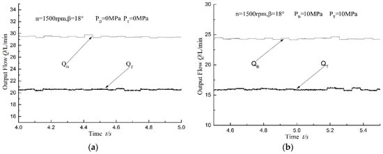
Figure 17.
The volume flow test results of Port B and Port T. (a) Slots B and Slots T output flow under zero megapascals load in Slots B and T; (b) Slots B and Slots T output flow under Ten megapascals load in Slots B and T.
6. Conclusions
As compared with the asymmetric axial piston pump (AAPP), the variable-displacement asymmetric axial piston pump (VAPP) can change the inlet and outlet ports of the flow directly by changing the swash plate angle of the pump. This is important in controlling the speed and position of the single rod cylinder and balancing the asymmetric flow of the two chambers of the cylinder. This method can help in reducing or eliminating the throttling losses and offer significant energy saving, at the same time. VAPP has wide application prospects in the modern engineering machinery.
Experiments and simulation results demonstrate that the operation principles of VAPP are practicable. In implementing the asymmetric pump-controlled asymmetric cylinder strategy in a closed circuit, the latest notion is suggested to counterbalance the unequal rate of flow of the asymmetric cylinder in the closed hydraulic circuit. The uniqueness of this new idea is that the innovativeness of the design as well as the valve plate’s configuration in the pump is also presented. Therefore, the pump has two ports for intake as well as two delivery systems.
In the future, the variable-displacement control methods and performance would be analyzed to further enhance the dynamics of VAPP’s pumping. Besides, it is recommended that its variable displacement components are studied further and designed.
Supplementary Materials
The supplementary materials are available online at http://www.mdpi.com/2076-3417/7/4/328/s1, Figure S1: The physical photo of VAPP, Figure S2: The test scene of VAPP.
Acknowledgments
The research work reported here is supported by National Natural Science Foundation of China (Grant No. 51375324); National-Shanxi Low Carbon of coal-based Foundation of China (NSFC) (Grant No. U1510206); and Taiyuan University of Science and Technology Graduate Science and Technology Innovation Project (Grant No. 20151021).
Author Contributions
Youshan Gao and Jie Cheng conceived and designed the experiments; Jie Cheng performed the experiments; Jiahai Huang and Long Quan analyzed the data; Jiahai Huang contributed reagents/materials/analysis tools; and Youshan Gao and Jie Cheng wrote the paper.
Conflicts of Interest
The authors declare no conflict of interest.
References
- Quan, L. Current state, problems and the innovative solution of electro-hydraulic technology of pump controlled cylinder. J. Mech. Eng. 2008, 44, 87–92. (In Chinese) [Google Scholar] [CrossRef]
- Hewett, A.J. Hydraulic Circuit Flow Control. U.S. Patent No. 5329767, 19 July 1994. [Google Scholar]
- Lawrence, P.D.; Salcudean, S.E.; Sepehri, N.; Chan, D.; Bachmann, S.; Parker, N.; Zhu, M.; Frenette, R. Coordinated and Force-Feedback Control of Hydraulic Excavators. In Proceedings of the 4th International Symposium on Experimental Robotics, ISER’95, Stanford, CA, USA, 30 June–2 July 1995. [Google Scholar]
- Rahmfeld, R.; Ivantysynova, M.; Weber, J. Displacement controlled wheel loader—A simple and clever solution. In Proceedings of the 4th International Fluid Power Conference, Dresden, Germany, 25–26 March 2004; pp. 183–196. [Google Scholar]
- Rahmfeld, R.; Ivantysynova, M. Energy saving hydraulic actuators for mobile machines. In Proceedings of the 1st Bratislavian Fluid Power Symposium, Častá-Píla, Slovakia, 2–3 June 1998; pp. 47–58. [Google Scholar]
- Heybroek, K.; Larsson, J.; Palmberg, J.O. Open Circuit Solution for Pump Controlled Actuators. In Proceedings of the 4th FPNI PhD Symposium, Sarasota, FL, USA, 13–17 June 2006; pp. 27–40. [Google Scholar]
- Williamson, C.; Ivantysynova, M. Pump mode prediction for four-quadrant velocity control of valveless hydraulic actuators. In Proceedings of the 7th JFPS International Symposium on Fluid Power Toyama 2008, Toyama, Japan, 15–18 September 2008; pp. 323–328. [Google Scholar]
- Wang, L.K.; Book, W.J.; Huggins, J.D. A hydraulic circuit for single rod cylinders. J. Dyn. Syst. Meas. Control 2012, 134, 1–11. [Google Scholar] [CrossRef]
- Zhang, X.; Quan, L.; Yang, Y. Theoretical Analysis and Experimental Research on Characteristics of Parallel Three Assignment Windows Axial Piston Pump. J. Mech. Eng. 2011, 47, 151–157. (In Chinese) [Google Scholar] [CrossRef]
- Zhang, X.; Quan, L.; Yang, Y.; Wang, C.; Yao, L. Output characteristics of a series three-port axial piston pump. Chin. J. Mech. Eng. 2012, 25, 498–505. [Google Scholar] [CrossRef]
- Huang, J.; Zhao, H.; Quan, L.; Zhang, X. Development of an asymmetric axial piston pump for displacement-controlled system. Proc. Inst. Mech. Eng. C J. Mech. Eng. Sci. 2014, 228, 1418–1430. [Google Scholar] [CrossRef]
- Ivantysyn, J.; Ivantysynova, M. Hydrostatic Pumps and Motors; Academia Books International: New Delhi, India, 2001; pp. 120, 130–133. [Google Scholar]
- Huang, J.; Yan, Z.; Quan, L.; Lan, Y.; Gao, Y. Characteristics of delivery pressure in the axial piston pump with combination of variable displacement and variable speed. Proc. Inst. Mech. Eng. I J. Syst. Control Eng. 2015, 229, 599–613. [Google Scholar] [CrossRef]
- Ma, J.E.; Fang, Y.T.; Xu, B.; Yang, H.Y. Optimization of cross angle based on the pumping dynamics model. J. Zhejiang Univ: Sci. A 2010, 11, 181–190. [Google Scholar] [CrossRef]


© 2017 by the authors. Licensee MDPI, Basel, Switzerland. This article is an open access article distributed under the terms and conditions of the Creative Commons Attribution (CC BY) license (http://creativecommons.org/licenses/by/4.0/).