1. Introduction
With the evolution of the Internet, one of the major concerns is to secure communicated information. Generally, information security is achieved by encryption (cryptography) and information hiding (steganography). In cryptography, information is encoded such that only authorized users can access it. In steganography, the information is concealed in a digital medium such that no one can notice whether the digital medium has the information inside it or not [
1].
In recent years, steganography techniques have been employed in various digital mediums, i.e., image, audio, video, and network protocols to achieve secret communication. Similarly, it is employed in various applications; Yesilyurt and Yalman used steganography to secure stored data elements in the cloud [
2]. Wu et al. [
3] employed steganography for secret sharing and authentication purposes. Xiang et al. used steganography for sending data from a mobile to the cloud and vice versa [
4]. Tondwalkar et al. [
5] used steganography process to secure localization of nodes in wireless sensor networks.
Usually, the objectives of image steganography consist of listed key factors, i.e., visual imperceptibility, embedding capacity, robustness, and security. Visual imperceptibility is considered as the resistance of the human visual system to identify the changes in the stego-image that can be measured by the peak signal to noise ratio (PSNR). Embedding capacity refers to the amount of concealed information inside a cover image. Robustness means extracting the original concealed information from stego-image regardless of various types of processing, i.e., cropping, scaling and filtering. Moreover, security against steganalysis and the integrity of secret data can be added to these objectives [
1]. Ideally, a steganography algorithm should be able to achieve larger embedding capacity with high visual imperceptibility while maintaining the security and integrity of secret data.
In this study, we will discuss the well-known image-based steganography techniques that deal with the least significant bit (LSB) substitution of the cover image pixels to hide secret data. LSB-based image steganography methods embed secret data in the least significant bits of the image pixel value. Usually, achieving the larger embedding capacity in LSB methods requires a large number of bits modification that can degrade the visual quality. Moreover, it relies on the fact that replacing one or more of the last 1–4 bits of cover image’s pixels is imperceptible to the human visual system, but some statistical tests could detect their replacement in appropriate locations [
6]. Therefore, one needs to design an embedding method requiring a lower number of bits modifications per pixel during the embedding process; the method should achieve a larger embedding capacity. In this study, the proposed method successfully achieves these objectives.
The organization of the paper is as follows. The literature review of LSB-based steganography methods is discussed in
Section 2.
Section 3 presents the proposed steganography method with discrete algorithm steps and explanations of embedding and extraction procedure.
Section 4 is dedicated to performance analysis (embedding capacity, visual imperceptibility, and statistical security) with a comparison of existing LSB-based steganography techniques. Finally, the conclusions and future direction of the research are discussed in
Section 5.
2. Related Work
This section is intended to give a brief literature review of LSB-based image steganography techniques since the proposed method is based on LSB substitution. Usually, in LSB-based methods, the secret data bits are substituted in
k-least significant bits of each pixel. In the literature, various types of LSB-based techniques have been proposed [
7,
8,
9,
10,
11,
12,
13,
14,
15,
16,
17,
18,
19,
20,
21,
22,
23] targeted at high capacity, visual quality and security.
One of the earliest adaptive LSB-based methods was introduced by Yang et al. [
7]. This method exploited the brightness, edges, and texture of the cover image to determine the number of
k LSBs for data embedding. The higher value of
k depends on the noise non-sensitive regions. Furthermore, an optimal pixel adjustment process is employed to enhance the visual quality. To obtain a larger embedding capacity, Tseng et al. [
8] proposed a method employing an adaptive LSB substitution for data embedding based on edge computation. A maximum of 4 LSBs are utilized during the embedding process. This method improved the embedding capacity but suffered from low visual imperceptibility (PSNR < 35 dB). Jung and Yoo [
9] proposed a semi-reversible data hiding technique involving interpolation and LSB substitution. The interpolation methods are used to scale up and scale down the cover image, where the LSB substitution (up to 3 LSBs) is employed for embedding. This method provides the larger embedding capacity while maintaining acceptable visual quality. However, this method did not discuss any security evaluation. Mohamed and Mohamed [
10] also employed the LSB substitution technique by dividing the image into two parts, one for embedding data and the other for indicating the embedding changes. This method increases the embedding capacity and improves the visual quality of the stego image, while the number of LSB substitutions is adaptive, ranging from 1–5. The visual quality of this method directly depends on the number of utilized LSBs. As the number of LSB substitutions increases, the visual quality of the stego-image decreases.
To further enhance the embedding capacity, researchers combined the other existing methods with the LSB technique. For example, Liao et al. [
11] proposed a larger embedding capacity based on LSB with the pixel value difference (PVD) [
12] based method. The average difference value of the four-pixel block is used to classify the high and low texture pixels block. Furthermore, the secret data are embedded using
k-bit modified LSB substitution. Similarly, Swain et al. [
13] integrated the LSB substitution with a PVD method. This method divides the image into 2 × 2 pixel blocks and applies
k-bit LSB in the upper left pixel of the block. Next, a PVD embedding process is applied to the base (upper-left) pixel with the remaining pixels of the block. This method provides the larger embedding capacity with the improved PSNR value. However, the
k-bits ranges are from 1 to 3, indirectly indicating that up to 3 LSBs of a pixel can be modified during the embedding process. In [
14], Hussain et al. proposed a recursive hybrid approach of LSB with other existing PVD and modification of prediction error (MPE) methods. First, it classified the lower and higher texture of an image; then it employed the LSB substitution and PVD methods. Next, to enhance the embedding capacity it recursively employed the PVD shift and MPE. This method provides larger capacity with acceptable PSNR. However, up to 4 LSBs are utilized for the embedding process. Similarly, Khodaei et al. [
15] introduced adaptive LSB embedding by utilizing the PVD characteristics. This method divides the cover image into two-pixel blocks, further computing the difference in value between the two pixels. The numbers of secret bits are estimated based on the computed difference value. Next, the adaptive LSB scheme is employed to embed the number of secret data bits inside the selected pixel blocks. This method also introduced a readjustment process to keep intact the stego-pixels with respective ranges; it successfully achieved the larger embedding capacity by retaining high visual imperceptibility. However, the maximum numbers of 4 LSBs are utilized during the embedding process. Another novel LSB-based technique [
16] proposed is bit inversion, aimed at improving the PSNR value. In this inversion technique, certain LSBs of the cover image pixels are changed if they are matched with a particular pattern. Thus, this improved the visual quality but suffered from the low payload.
Recently, another texture-adaptive (i.e., edge-based) LSB method was proposed [
17]. In this method, the cover pixels are classified into edge areas and non-edge areas. The edge information is determined by the 3 most significant bits (MSBs) of the cover pixels, where the rest of 5 LSBs are adaptively employed by the LSB substitution. This method obtained high embedding capacity while retaining acceptable visual quality. However, a maximum of 5 LSBs are employed in the embedding process. Similarly, Lee [
18] proposed an adaptive LSB method for color images on smartphones. For all RGB channels, it proposed various LSB replacement strategies i.e., all 4 bits in each RGB channel and similarly 4 bits in R, two-2 bits in G, B channels and so on. This method achieved an average 2.8 bits per channel while it retains the high value of PSNR 43.7 dB. Its 4-bit LSB substitution strategy may employ up to 4 LSBs of each channel for embedding.
On the other hand, to ensure data security, various methods employed the compression and encryption techniques to reduce the data size and increase the data security before the embedding process. For example, Kuo et al. [
19] employed run-length encoding (RLE) to compress the secret data bits. Furthermore, it efficiently utilized the multi-bit generalized exploiting modification direction for embedding that indirectly reduces the number of modified pixels of a stego-image. This method maintained high visual quality and capacity (due to compression) but it effectively provided low embedding capacity. Similarly, Sethi and Kapoor provide better data security along with imperceptibility and capacity [
20]. First, the secret data is encrypted using the Advanced Encryption System (AES) algorithm and converted into four-bits fixed blocks. The LSB substitution is then performed on the basis of four bits. Although the security of data is improved the computational cost of encryption seems to be a major concern. Recently, Muhammad et al. [
21] proposed a channel indicator-based lightweight encrypted embedding method. It provides multi-level encryption for secret data and as well as stego-key. This method retains high imperceptibility and security against detectability but suffers from low embedding capacity.
Most of the aforementioned recent methods are summarized in
Table 1. This shows the clear picture of embedding capacity versus visual quality of existing methods. All the statistics are directly taken from the studies, where the embedding capacity depicts the average number of embedding bits per pixel (bpp). Similarly, visual quality measured in peak signal to noise ratio (PSNR) and security of undetectability is shown in the 3rd and 4th column. Finally, the maximum no. of LSBs (or bits) that would be modified during the embedding process of each technique is shown in the last column of the table.
As can be observed in all the aforementioned LSB-based techniques; these were mainly focused on following steganography objectives, i.e., to increase the embedding capacity [
8,
10,
13,
14,
15], to enhance visual imperceptibility [
13,
15,
18,
23] and to improve security against detectability and hidden data [
13,
14,
20,
21]. However, we found tradeoffs among all these objectives because these are correlated to one another. As we noticed (see
Table 1), most of the larger capacity-based LSB methods [
8,
10,
13,
14,
15,
17] employed the maximum LSBs or modify the maximum number of bits in each pixel (i.e., 3–5 bits). This maximum bits modification in pixels increases the visual distortion between cover and stego-pixels (that can be seen as low PSNR value 30 to 33 dB). Consequently, it reduces the stego-image visual quality and increases the risk of steganalysis detection attacks. (However, most of the existing techniques did not perform any steganalysis.) Therefore, a novel steganography approach is required that must achieve larger embedding capacity while retaining the lower number of bits changed per pixel or lesser modification in pixel bits. Furthermore, it must maintain the maximum visual imperceptibility and security against steganalysis detection attacks. In the next section, we will discuss the proposed method.
3. The Proposed Method
In this section, we will present the proposed LSB-based steganography method that aimed at enhancing embedding capacity, achieving good visual quality, and security against steganalysis detection attacks. The proposed method extends the concept of LSB substitution. This employed the mapping of secret data bits with cover pixel bits, where the record of mapping is maintained by the LSB substitution in cover pixels. For data security, the proposed method also applies the permutation on secret data bits using a shared key.
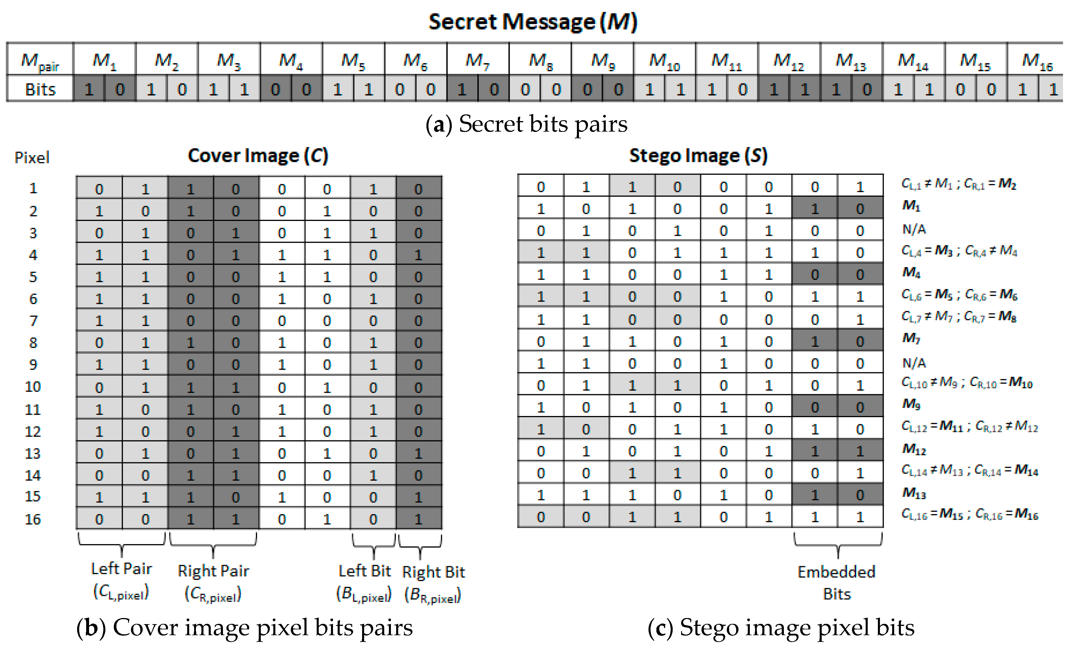
In the embedding process, first, the secret data bits are grouped into two secret bits pairs, i.e.,
M1(10),
M2(10),
M3(11), … as shown in
Figure 1a. Similarly, all the cover pixels bits are also categorized as pairs, i.e., Left Pair (
CL,pixel) and Right Pair (
CR,pixel) depicted in
Figure 1b.
CL,pixel denotes the 7th and 8th MSBs of the cover pixel, and similarly,
CR,pixel denotes the 5th and 6th MSBs of the cover pixel. Both
CL,pixel and
CR,pixel bits would be used for mapping with secret data bits pair. In the same way, the 1st and 2nd LSBs of cover pixel also denoted with Right Bit (
BR,pixel) and Left Bit (
BL,pixel) and used as an indicator for mapping of pixels pair.
BL,pixel and
BR,pixel are closely coupled with
CL,pixel and
CR,pixel in terms of indicator bits, respectively. However, the mapping strategies consist of the following cases.
- Case 1:
If first secret bit pair (i.e., M1) is matched with the CL,pixel of a cover pixel then BL,pixel is replaced with ‘1’ otherwise replaced it with ‘0’.
- Case 2:
Similarly, if the second secret bit pair (i.e., M2) is matched with CR,pixel, it substitutes BR,pixel with ‘1’ otherwise replaces it with ‘0’.
- Case 3:
If either BL,pixel or BR,pixel is ‘0’, then the 2-LSBs of very next cover pixel would be replaced with the previous unmatched secret bit pair (i.e., M1 or M2).
- Case 4:
If both BL,pixel and BR,pixel are ‘0’, it would indicate the skipped mapped block (which does not contain any mapping).
For example, from
Figure 1, the first pixel of cover image has the following values,
CL,1 = 01,
CR,1 = 10,
BL,1 = 1,
BR,1 = 0 and the secret bits pair are
M1 = 10,
M2 = 10. From case 1,
CL,1 ≠
M1, i.e., 01 ≠ 10, so it replaces the (
BL,1) 1 with 0. Similarly, from case 2,
CR,1 =
M2, so it substitutes the 1 in
BR,1 location. Next, the case 3 conditioned would be satisfied, i.e., if
BL,1 = 0 or
BR,1 = 0, then embed the remaining unmatched secret pair that was
M1 = 10. These
M1 = 10 are substituted in the 2-LSBs of the next pixel, i.e.,
BL,2 = 1 and
BR,2 = 0, this can be shown in the second pixel. Similarly, this process can be extended for rest of the pixels.
Table 2 describes the complete embedding steps.
In the extraction phase, it follows the similar embedding group pairing process of stego-pixels, i.e., Left and Right Pair with Left and Right Bit, etc. The secret data bits are extracted by referring to the indicator bits (i.e., BL,pixel or BR,pixel) that were substituted by the two LSBs in each pixel. The extraction cases are as follows.
- Case 1:
If BL,pixel is ‘1’ and BR,pixel is ‘0’, restore CL,pixel as a first secret pair (M1) and restore the 2-LSBs of the next pixel as a second secret pair (M2).
- Case 2:
If BL,pixel is ‘0’ and BR,pixel is ‘1’, restore CR,pixel as a second secret pair (M2) and restore the 2-LSBs of the next pixel with a first secret pair (M1).
- Case 3:
If both BL,pixel and BR,pixel are ‘1’, then restore the first secret pair (M1) from CL,pixel and similarly, restore the second secret pair (M2) from the CR,pixel bits.
- Case 4:
If both BL,pixel and BR,pixel are ‘0’, it would indicate the unmapped block (which does not contain any mapping).
For example, as shown in
Figure 2, the first pixels of stego-image bits are (01 10 00 01). This satisfied the case 2, the stego-pixel’s
BL,pixel is ‘0’ and
BR,pixel is ‘1’, this indicates extraction of
CR,1 = 10 as the second secret pair, i.e.,
M2. Furthermore, extract the 2 LSBs (i.e., 10) from the 2nd pixel of stego-image
M1. For 3rd stego-pixel, case 4 is satisfied because both
BL,pixel and
BR,pixel are ‘0’, which means this is a skipped unmatched block. Similarly, this process can be extended for the rest of the pixels to extract the secret data bits from the stego-image.
Table 3 describes the complete extraction steps.
4. Experimental Results
The proposed method was implemented using C++ on an Intel(R) Core(TM) i7 2.70 GHz CPU with 8 GB RAM on Windows 10. For performance evaluation, we employed a well-known standard image dataset by Signal and Image Processing Institute from University of Southern California namely USC-SIPI [
24] with grayscale (8 bits per pixel) based images, i.e., Aerial, Airplane, APC, Boat, Car, Couple, Gray21, Motion, Ruler, Stream, Tank, and Truck as shown in
Figure 3. For secret data embedding, a random function from Microsoft Visual Studio 2008 (Version 9.0.21022.8 RTM, Microsoft, Washington, United States) was used to generate the bits stream for secret data.
For a comprehensive performance analysis, we categorized the evaluations into the following sub-sections. Firstly,
Section 4.1 consists of the maximum obtained embedding capacity with various visual quality evaluation parameters, i.e., PSNR, bpp, and modified bits per pixels. Secondly, in
Section 4.2, we evaluated the performance of the visual quality of the proposed method on various embedding rates as compared to existing techniques. Similarly, for security aspects of the proposed method against existing methods,
Section 4.3 and
Section 4.4 discussed the well-known detection attacks, i.e., histogram analysis and RS analysis. However, in all of the above evaluation categories, we employed the similar evaluation procedures (i.e., image dataset and PSNR) on proposed and existing Yang et al., Liao et al. and Khodaei et al. [
7,
11,
15] methods.
4.1. Embedding Capacity and Visual Quality Analysis
In this section, the performance of embedding capacity and visual quality is compared in three ways. First, the performance of the proposed method with Yang et al. [
7], Liao et al. [
11], and Khodaei et al. [
15] are shown in
Table 4. Secondly, the embedding capacity vs visual quality performance over the complete USC-SIPI dataset is shown in
Table 5. Finally, the performance of the proposed method is compared with the most recent LSB-based methods (in
Figure 4).
The embedding capacity is calculated as the maximum number of secret data bits that can be embedded into the cover image. Bits per pixel are determined using Equation (1), where W and H are the width and height of the cover image respectively. PSNR is adopted to evaluate the visual quality or evaluate the distortion of the cover images after embedding secret data. The PSNR is computed as shown in Equation (2). A high value of PSNR illustrates a low degree of image distortion. Conversely, a small PSNR value indicates a larger distortion between the cover image and the stego image.
Mean square error (MSE) is the measure of an average of the squares of the difference between the pixel intensities of the stego and the cover images. That is defined in Equation (3), where and are the pixel values of the stego and cover images, respectively. The smaller the MSE value, the better the image quality; the higher the MSE value, the greater the distortion. MSE is inversely proportional to the PSNR, which demonstrates that the higher the value of PSNR, the lower the MSE value produced. So, a higher PSNR would be considered as good or an indication of low image distortion.
From the experiments as shown in
Table 4, the average embedding capacity obtained from the proposed method is higher than in Yang et al. [
7], Liao et al. [
11], and Khodaei et al. [
15]. The proposed method is able to embed a payload from 823,499 bits (or 805 KB) to 872,136 bits (or 852 KB). This achieved the embedding bits per pixel ranging from 3.14 to 3.33 bpp with PSNR values from 41.59 to 42.66 dB. However, the Khodaei et al. and Liao et al. methods had the lower average payload of 820,741 bits (or 802 KB) and 815,682 bits (or 797 KB), respectively. The Yang et al. method resulted in an average payload of approximately 765,120 bits (or 748 KB). From
Table 4, it was proved that the proposed method obtained the highest average embedding capacity of 849,347 bits (or 830 KB) and average 3.24 bpp. We can say the proposed method is able to embed 28,606, 33,664, and 84,227 more bits than the Khodaei et al., Liao et al., and Yang et al. methods, respectively.
As seen in
Table 4, the proposed method can also perform better to produce less distorted stego-images than existing methods in terms of higher PSNR and a lower number of modified bits per pixel statistics. The proposed method achieved the average modified bits per pixel of 1.87 bits (ranging from 1.69 to 1.98 bits) while existing methods had higher modified bits per pixel, i.e., Yang et al. with 2.25, Liao et al. with 2.31, and Khodaei et al. with 2.63. Generally, the lower modification bits per pixel value produces a less distorted stego-image which indirectly helps to enhance the PSNR value. Hence, it is proved, and as shown in
Table 4 statistics, that the proposed method yielded higher average PSNR of 42.15 dB against the compared methods. The proposed method has a PSNR value 2.27 dB higher than achieved by Yang et al., 2.86 dB higher than Liao et al., and 3.74 dB higher than the Khodaei et al. method.
Finally, the performance of embedding capacity and PSNR are compared for the complete 301 image samples in the USC-SIPI dataset, categorized in four volumes, i.e., Textures, Aerials, Miscellaneous, and Sequences as shown in
Table 5. The experimental results show that the proposed method’s average embedding capacity is higher than that of the existing methods as highlighted in bold font. Similarly, the PSNR of the proposed method is the highest among others in all tested image resolutions. The overall results demonstrate that the proposed method has better embedding capacity while maintaining higher visual quality and requires a lower number of bits per pixel modification as compared to existing methods. The highest capacity achieved in a proposed method is based on its internal data bits mapping and indicator strategy. It can be seen that the proposed method indirectly embeds up to 4 secret bits per pixel while limiting the modification of bits per pixel up to 2.
The statistics in
Figure 4 show the comparisons of proposed and recent data embedding approaches. The embedding capacity of the proposed method is far better than that of all the other compared methods except Bai et al. [
17], where the PSNR value of Bai et al. [
20] is too low (−13 dB) as compared to the proposed method. Similarly, the proposed method achieved the higher PSNR value while retaining the lower number of (only 2) LSBs used. However, Wien [
22] utilized only 1 LSB, but the embedding capacity and visual quality statistics are quite low as compared to the proposed method. In conclusion, we can say the proposed method outperformed all the compared methods in terms of embedding capacity, visual quality and maintaining the minimum no. of LSBs employed for the embedding process.
4.2. Peak Signal to Noise Ratio (PSNR) Analysis on Various Embedding Levels
In this section, we evaluated the visual quality of the proposed method at different embedding rates to verify whether the proposed method has consistent performance of visual quality at various embedding levels. The graphical representation of PSNR values of images for different sizes of secret bits are shown in
Figure 5a–f. The methods developed by Yang et al. [
7], Liao et al. [
11], and Khodaei et al. [
15] are compared with the proposed method to observe the differences in performance. For the Gray21 image, the capacity vs PSNR graph is as shown in
Figure 5a. Once the embedding capacity is high, i.e., 500,000 bits, the proposed method obtained the highest PSNR of 43.17 dB, while the compared methods achieved lower PSNR, i.e., 41.70 dB (Yang et al.), 40.20 dB (Liao et al.), and 39.30 dB (Khodaei et al.). Similarly, if the embedding bits are 250,000, again the proposed method achieved a higher PSNR (44.40 dB) while the others obtained 42.50, 41.90, and 40.23 dB, respectively. Furthermore, if the embedding capacity is around 50,000 bits, the proposed method has far better PSNR up to 48.65 dB as compared to existing methods.
From
Figure 5b of the Motion image, the proposed method obtained the maximum PSNR 43.21 dB at 500,000 bits embedding. However, the compared methods achieved low PSNR as compared to the proposed method, i.e., [
7] 41.39 dB, [
11] 40.45 dB, and [
15] 38.96 dB at the same 500,000 bits. Similarly, the proposed method achieved the maximum PSNR (48.50 dB) at 50,000 bits for Ruler image in
Figure 5c and 48.20 dB for Stream image in
Figure 5d.
In the same way, from
Figure 5e, the proposed method obtained the highest PSNR 43.19 dB at 500,000 bits while the compared methods recorded low PSNR, i.e., 40.89 dB [
7], 39.93 dB [
11], and 39.05 dB [
15] for the Tank image. In
Figure 5f, the highest PSNR achieved by previous methods is 44.78 dB for Yang et al., 46.52 dB for Liao et al., and 42.67 dB for Khodaei et al., while the proposed method obtained the highest PSNR of 48.53 dB for the Truck image. On average, PSNR results at the lowest embedding capacity are obtained by the methods: 43.99 dB [
7], 45.10 dB [
11], 42.10 dB [
15], and the proposed method with 48.43 dB. At 500,000 bits, the proposed method recorded the highest PSNR with 43.19 dB followed by Yang et al. with 41.16 dB, Liao et al. with 40.14 dB, and Khodaei et al. with 39.01 dB. Therefore, the proposed method yields the highest PSNR at different embedding capacities against Yang et al., Liao et al., and Khodaei et al.
Consequently, from experiments, the proposed method outperformed the compared methods; it was proven that the proposed method retains high visual imperceptibility irrespective of embedding rates. The reason behind achieving the better results depends on the maximum number of bits mapping strategy while reducing the number of bits modification into the pixel.
4.3. Histogram Analysis
For measuring the robustness against common statistical attacks, the histogram analysis [
25] between the cover and stego images of the proposed method are presented. The histograms are generated from the embedding process using Aerial, Airplane, Boat and Couple images as presented in
Figure 6. Generally, by embedding the secret bits in the cover image, the frequency of pixels values are changed and can become visible in the histogram.
Figure 6c,g,k,o shows the frequency histogram of the cover images. Meanwhile,
Figure 6d,h,l,p shows the frequency histogram of the stego images. As observed from histograms, the disparities between the constructed histograms are comparatively less for all tested images. The results indicate that distortions produced from embedding process are unnoticeable to human visual perception. The analysis results show that there is no significant difference found in histograms of the cover and stego images. The embedded information is not easily detected by the difference histogram analysis. Thus, histogram-based steganalysis attacks are not possible for the proposed method. The security of hidden secret is well protected while keeping the advantage of low visual distortion introduced by the proposed method.
4.4. Security against RS Steganalysis
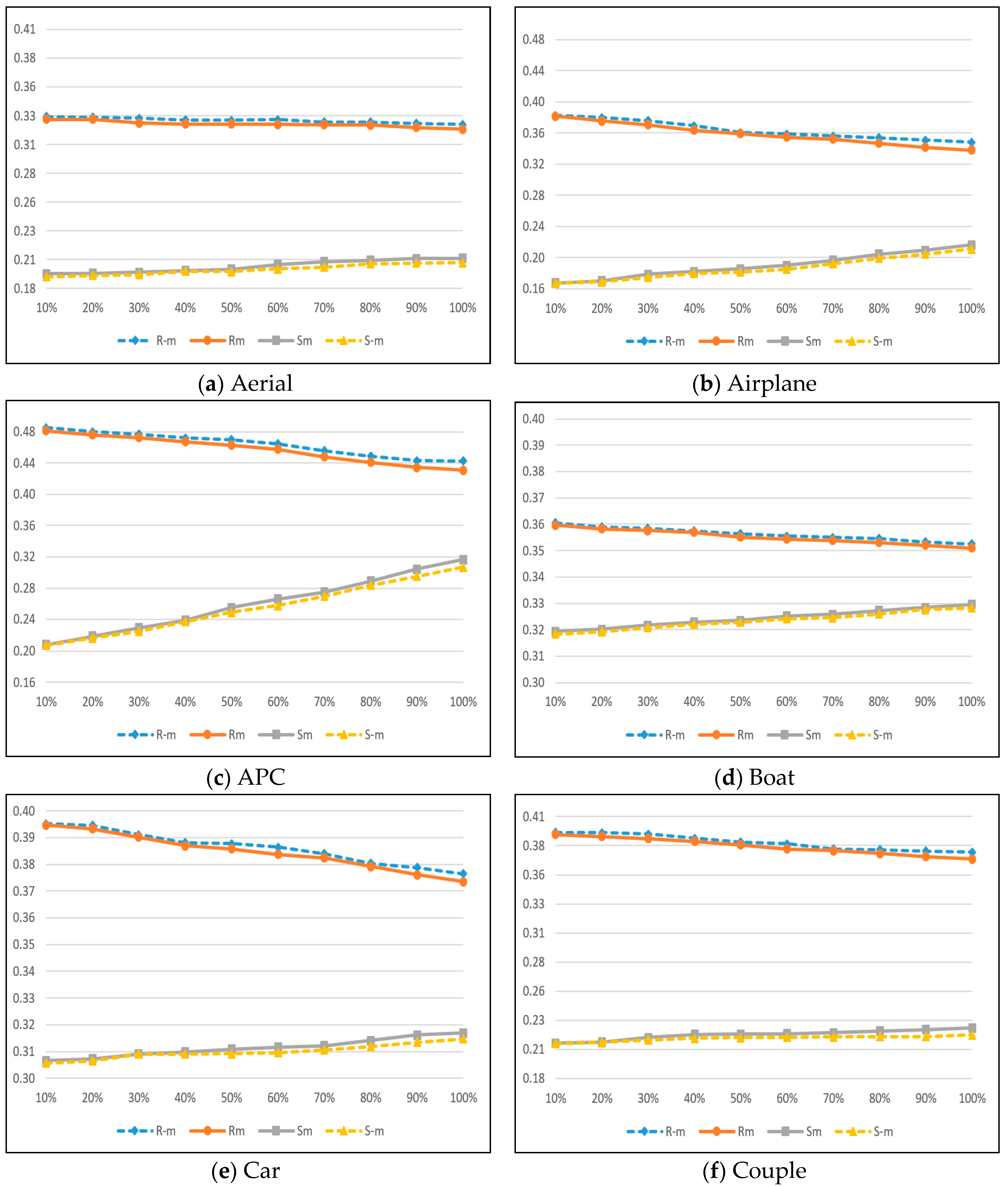
The security of the proposed method against the statistical RS (Regular and Singular groups) steganalysis method [
6] is depicted in
Figure 7. The RS steganalysis is based on discrimination function (
DF) with
M and −
M as flipping masks. Furthermore,
RM,
R−M,
SM, and
SM parameters are used to find the magnitude of the pixel block using
DF function. If the parameters satisfy
RM ≈
R−M >
SM ≈
S−M, then no hidden data are in the respective image. When an image has hidden data in its least significant bits,
R−M and
SM increases, whereas
RM and
S−M decreases and is exposed by RS analysis. In the RS analysis, we used
and
as
M and −
M, respectively. The
x-axis on the RS analysis graph represents the percentage of hidden data in the stego image, and the
y-axis denotes the relative percentages of regular (
RM,
R−M) and singular (
SM,
S−M) groups with the application of the above masks (
M, −
M).
The RS detection results can be seen in
Figure 7 with the proposed method for the Aerial, Airplane, APC, Boat, Car, and Couple images. In
Figure 7a, the differences between singular and regular parameters remain constant and close to each other even when the hiding capacity increases. As shown in
Figure 7d, the RS detection differences values of the proposed method are very close to each other between
R−M and
RM, and between
S−M and
S−M curves. For
Figure 7b,c,e,f images, the differences between regular and singular groups are maintained close to each other via the proposed method. These results indicate that the proposed method is secured against RS steganalysis detection attacks.
The maximum differences of detection parameters, i.e.,
RM −
R−M, and
SM −
S−M for the compared methods [
7,
11,
15] are shown in
Table 6. From the statistical analysis, it is evident that the proposed method has the smallest average difference in both regular and singular groups, i.e., 0.1853% and 0.1451%, respectively. However, Yang et al.’s method has a slightly higher average difference for both regular singular groups (0.1947%, 0.1542%). Similarly, Khodaei et al. and Liao et al. methods have higher average difference results for both regular groups (0.2160% and 0.2358%) and singular groups (0.1697% and 0.1934%). In short, the proposed method has the smallest differences against all the compared methods, thus indicating the fewer detection artifacts in stego-images. Moreover, we can say that the proposed method has more capability to resist the RS steganalysis detection attacks.


 ,
, 


