Article

Design and Testing of a LUT Airfoil for Straight-Bladed Vertical Axis Wind Turbines

1
School of Energy and Power Engineering, Lanzhou University of Technology, Lanzhou 730050, China
2
Gansu Provincial Technology Centre for Wind Turbines, Lanzhou 730050, China
3
Key Laboratory of Fluid machinery and Systems, Lanzhou 730050, China
4
School of Naval Architecture, Ocean and Civil Engineering, Shanghai Jiao Tong University, Shanghai 200240, China
5
State Key Laboratory of Ocean Engineering, School of Naval Architecture, Ocean and Civil Engineering, Shanghai Jiao Tong University, Shanghai 200240, China
6
Collaborative Innovation Center for Advanced Ship and Deep-Sea Exploration, Shanghai Jiao Tong University, Shanghai 200240, China
7
Key Laboratory of Hydrodynamics (Ministry of Education), Shanghai Jiao Tong University, Shanghai 200240, China
8
Jiangsu Key Laboratory of Hi-Tech Research for Wind Turbine Design, Nanjing University of Aeronautics and Astronautics, Nanjing 210016, China
*
Author to whom correspondence should be addressed.
Appl. Sci. 2018, 8(11), 2266; https://doi.org/10.3390/app8112266
Submission received: 29 September 2018 / Revised: 11 November 2018 / Accepted: 13 November 2018 / Published: 16 November 2018
(This article belongs to the Special Issue Wind Turbine Aerodynamics)

Abstract

:
The airfoil plays an important role in improving the performance of wind turbines. However, there is less research dedicated to the airfoils for Vertical Axis Wind Turbines (VAWTs) compared to the research on Horizontal Axis Wind Turbines (HAWTs). With the objective of maximizing the aerodynamic performance of the airfoil by optimizing its geometrical parameters and by considering the law of motion of VAWTs, a new airfoil, designated the LUT airfoil (Lanzhou University of Technology), was designed for lift-driven VAWTs by employing the sequential quadratic programming optimization method. Afterwards, the pressure on the surface of the airfoil and the flow velocity were measured in steady conditions by employing wind tunnel experiments and particle image velocimetry technology. Then, the distribution of the pressure coefficient and aerodynamic loads were analyzed for the LUT airfoil under free transition. The results show that the LUT airfoil has a moderate thickness (20.77%) and moderate camber (1.11%). Moreover, compared to the airfoils commonly used for VAWTs, the LUT airfoil, with a wide drag bucket and gentle stall performance, achieves a higher maximum lift coefficient and lift–drag ratios at the Reynolds numbers 3 × 10⁵ and 5 × 10⁵.

1. Introduction

In an urban or offshore environment, Vertical Axis Wind Turbines (VAWTs), especially the lift-driven type, have unique advantages due to their lower cost, lower noise, simpler structure, and ability to actively accept wind energy from different directions [1,2,3]. Moreover, with the development of distributed wind energy, VAWTs function more efficiently in certain areas, particularly areas with large fluctuations in wind direction [4,5]. However, compared to Horizontal Axis Wind Turbines (HAWTs), for a long time, VAWTs have experienced slow development and received very little financial support. One reason is the lack of completed theoretical research on VAWTs. For example, although the multiple flow tube theory, which is based on blade element momentum (BEM), is applied to the VAWT design, the results are still far from satisfactory because of the lack of adequate theoretical correction [6]. Another possible reason is that HAWTs have thousands of special airfoils, such as the FFA (FLYGTEKNISKA FORSOKSANSTALTEN) series, DU (Delft University) series, RISØ series, and S series. However, little research has been performed on the airfoils for VAWTs, resulting in the lack of good blades for VAWTs, which further affects VAWT development. Meanwhile, the airfoil plays an essential role in the design of a wind turbine and greatly affects the wind turbine’s performance. Therefore, the above factors have led to not only the slow development of VAWTs but also to a heavily debated topic, i.e., the types of airfoil to use in a VAWT [7].
Many studies that have been conducted on the aerodynamic performance of VAWTs have been carried out with a focus on commonly used aircraft airfoils. In particular, in previous research, the symmetrical airfoils of the NACA 00XX series, such as NACA 0012, NACA 0015, and NACA 0018, are widely applied to VAWTs because they help to improve the power coefficient of VAWTs [8]; nevertheless, symmetrical airfoils are unable to properly self-start in VAWTs [9]. Other studies [10,11] have pointed out that VAWTs with a symmetrical airfoil result in poor performance at low Reynolds numbers (Re), because the self-start difficulty is worsened under such conditions. Studying the effects of the airfoil on the aerodynamic performance of VAWTs, Mohamed et al. [12] focused on 25 kinds of airfoils, and the results indicate that the cambered airfoil LS(1)-0413 increases the power coefficient compared to NACA 0018. In addition, the cambered airfoil NACA 63-415 has a wider operating range. The thickness and camber of the airfoil influence VAWTs according to studies of the NACA-4 digit modified airfoil family or the NACA four-series airfoils [13,14,15]. However, when the VAWTs work at a higher tip-speed ratio, the aerodynamic performance of the VAWTs decreases with the constant increase in both the camber and thickness of the airfoil [11,13]. Therefore, based on these previous results, it is necessary to consider a moderate camber and moderate thickness in the design of an airfoil for use in a VAWT.
Additionally, according to previous research, some specially purposed airfoils are developed for VAWTs. Achieving great success, the Sandia National Laboratory and Natural Resources Canada carried out a huge volume of work on airfoils for VAWTs through wind tunnel and field experiments [16,17]. The studies of the Sandia National Laboratory show that the natural laminar flow airfoil is suitable for VAWTs. As a result, the Somers airfoils are designed based on their research results; however, they are applied to the curved-bladed Darrieus turbines primarily [7]. Meanwhile, Islam performed meaningful work on VAWTs [9,18,19] by demonstrating the proper camber and thickness most suitable for VAWTs. Moreover, the MI-VAWT1 airfoil is designed to solve the problems of the overall cost, the aerodynamic performance, and blade strength. At the same time, the aerodynamic performance of the MI-VAWT1 airfoil is superior to that of NACA 0015. In addition, the Technical University of Denmark (DTU) has been dedicated to the research of airfoils for VAWTs. Its studies [20,21] depict some very thick airfoils that were designed by considering the structural stiffness of the blade and the aerodynamic characteristics. For instance, the AIR001 airfoil (max. thickness of 25%) can improve the aerodynamic performance in the case of a larger tip-speed ratio, while the DU12W262 airfoil (max. thickness of 26.2%) can increase blade strength. Other research [9,22,23] has explored specially purposed airfoils for VAWTs, such as the DU06-W-200, EN0005, WUP1615, and “TWT series” airfoils from Tokai University. In brief, there are different design aims for different special-purpose airfoils.
As mentioned above, a great deal of investigation has been done to understand the aerodynamic performance of VAWTs and the characteristics of the airfoil. However, compared to HAWTs, the research on special-purpose VAWT airfoils, which affect the aerodynamic performance of VAWTs, is limited. In addition, there exists room for improvement of many aspects, such as the maximum lift coefficient, maximum lift–drag coefficient, wide drag bucket, and stall performance, in the aerodynamic performance of the existing airfoil. Additionally, it is very important that the airfoil has good performance at a low Re due to the operating environment of VAWTs. Therefore, the objective of this paper is to design an airfoil—named the LUT airfoil, a reference to Lanzhou University of Technology—that shows good aerodynamic characteristics for VAWTs and to investigate the characteristics of the airfoil at low Re values by wind tunnel experiments. This paper is divided into three main parts: illustrating the design basis and optimization method in Section 2, describing the experimental equipment and procedures in Section 3, and reporting the profile and the aerodynamic performance of the LUT model in Section 4.

2. Basis and Method of Design for the LUT Airfoil

2.1. Design Basis

Figure 1 shows the structure and operation of an H-type VAWT (H-VAWT). The rotational axis of H-VAWTs is always perpendicular to the incoming airflow Vin, which results in a constantly changing local angle of attack and a readily occurring dynamic stall [24], especially with a rotor at low speed. Moreover, the VAWTs typically operate in low-Re environments. Nevertheless, reasonable design of special airfoil for VAWTs is one of the effective methods to solve the above problems. Therefore, the characteristics of an airfoil at a low Re and a wide range of angles of attack (α) were also considered factors in the design of the LUT airfoil.

2.2. LUT Airfoil Optimization and Design Method

Optimization algorithm and numerical simulation are widely used in design of the airfoil for VAWTs. Therefore, in this study, the sequential quadratic programming (SQP) method [25,26] was adopted to design the LUT airfoil, because it can properly solve the problem of constrained optimization, maintain the approximate second-order drop speed, and effectively handle constraint conditions. The optimization process is detailed in the following.
The optimization problem can essentially be boiled down to a nonlinear programming problem, as follows:
{    M i n          f ( X ) s . t .      c i ( X ) = 0      i = 1 , 2 , , m e c i ( X ) 0      i = m e + 1 , , m
where f ( X ) is the objective function, c i ( X ) is the constraint condition, m e is the number of constraint conditions of the equation, and m is the number of total constraint conditions.
For the convenience of derivation, the Lagrange function of Equation (1) is:
L ( X , λ ) = f ( X ) i = 1 m e λ i c i ( X )
The gradient vector of this function of x and the Hesse matrix are denoted, respectively, by:
x L ( X , λ ) = f ( X ) i = 1 m e λ i c i ( X )
x 2 L ( X , λ ) = 2 f ( X ) i = 1 m e λ i 2 c i ( X )
For λ = ( λ 1 , λ 2 , , λ m , ) , the gradient vector and Hesse matrix of the Lagrange function of X and λ , corresponding to L ( X , λ ) and 2 L ( X , λ ) , respectively, are defined as follows:
L ( X , λ ) = [ f ( X ) c ( X ) λ c ( X ) ]
2 L ( X , λ ) = [ x 2 L ( X , λ ) c ( X ) c ( X ) T 0 ]
where c ( X ) is the Jacobian matrix for the vector function at X , that is, the matrix of n × m with the partial derivative c j ( X ) x i of the (i, j) element. The first-order Taylor of the gradient vector is expanded to:
L ( X , λ ) = L ( X k , λ k ) + 2 L ( X k , λ k ) [ X X k λ λ k ]
where k represents the current iteration. It is a necessary condition that the gradient is equal to zero for the optimal solution of the Lagrange function, that is, L ( X , λ ) = 0 . Substituting Equations (5) and (6) into the first-order Taylor expansion of the gradient vector produces:
[ x 2 L ( X k , λ k ) c ( X k ) c ( X k ) T 0 ] [ X X k λ λ k ] = [ f ( X k ) + c ( X k ) λ k c ( X k ) ]
By defining d = X X k and replacing x 2 L ( X k , λ k ) with the Hessen matrix B k , we can obtain:
[ B k c ( X k ) c ( X k ) T 0 ] [ d λ ] = [ f ( X k ) c ( X k ) ]
This equation is the exact K-T condition of the quadratic programming problem:
{ M i n       1 2 d T B k d + f ( X k ) T d s . t .       c ( X k ) T d + c ( X k ) = 0
where the vector d represents the search direction, and B k is the approximation of the Hessen matrix. In this way, a common constraint problem is transformed into a quadratic programming problem. Moreover, on this basis, it can be naturally extended to inequality constraints:
{ M i n     1 2 d T B k d + f ( X k ) T d s . t .      c ( X k ) T d + c ( X k ) = 0 c ( X k ) T d + c ( X k ) 0
The above SQP method is only locally convergent in theory. To converge to the optimal solution, a one-dimensional search is required to ensure its overall convergence. The search direction d is obtained by Equation (11), which is the downward direction of many penalty functions. For example:
F σ ( X ) = f ( X ) + σ [ i = 1 m e | c i ( X ) | + i = m e + 1 m | m i n { c i ( X ) , 0 } | ]
where σ is the penalty factor that satisfies σ > max { | λ i |   i = 1 , 2 , , m } . A one-dimensional search based on F σ ( X k , d ) < 0 is carried out along with the d direction, and then the step length t k that satisfies F σ ( X k + t k d ) < F σ ( X k ) is obtained. Meanwhile, the next iteration point can be obtained:
X k + 1 = X k + t k d k
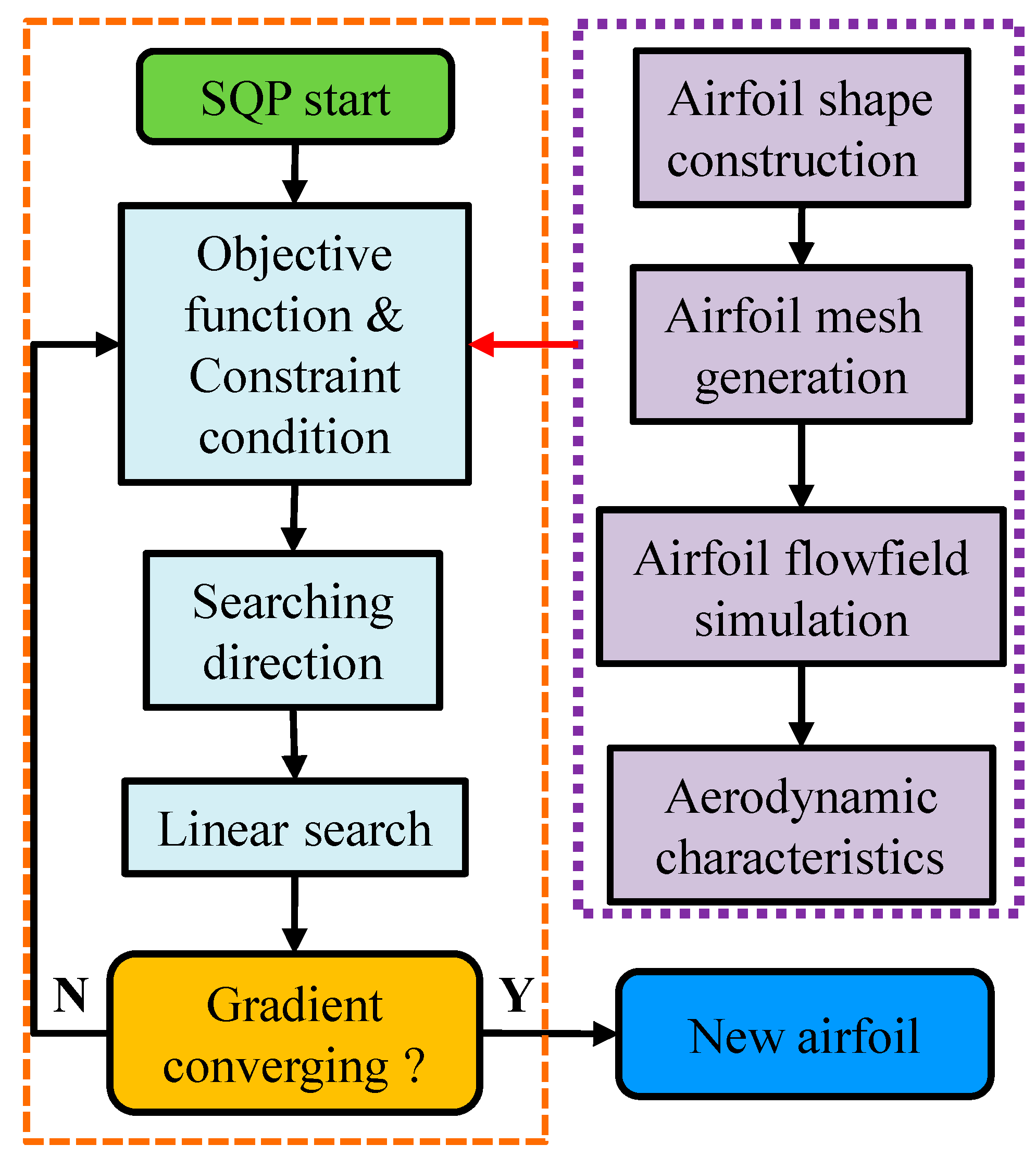
The flowchart describing the optimization of the airfoil’s aerodynamic shape based on the SQP method is shown in Appendix A.
Additionally, the aerodynamic performance of the LUT airfoil is obtained under free transition by employing ANSYS Fluent code during the process of optimization; the numerical solution of the Reynolds-averaged Navier–Stokes (RANS) equation is used, and the Shear–Stress–Transport (SST) k-ω turbulence model is employed [27]. Pressure–velocity coupling is achieved by the SIMPLEC scheme, where the second-order upwind discretization scheme is utilized to calculate the pressure, and the second-order implicit formula is adopted to test temporal discretization. Figure 2a demonstrates the geometric scheme and the boundary conditions of the numerical simulation. The walls of the airfoil are set as non-slip walls, while the other walls are set as free-slip walls. The O-grids are positioned near the airfoil, and the first grid’s spacing is less than 1 × 10⁻⁵ to ensure that the Y+ is less than 1.
The design results are introduced in the results and discussion section.
This study required a LUT airfoil with a good aerodynamic performance; meanwhile, to ensure the structural strength of the blade for the LUT airfoil, the corresponding airfoil thickness and bending constraints were considered. Therefore, the objective function and constraint conditions can be summarized as:
{               M i n          C d / C L s . t .      max ( t h i c k n e s s ) > max ( t h i c k n e s s 0 ) max ( c u r v e ) > max ( c u r v e 0 )
where the thickness0 and curve0 represent the optimized benchmark corresponding to the maximum thickness and the maximum camber of the NACA 0018 airfoil, respectively; the design Reynolds number is 5 × 10⁵; and the design angle of attack is α = 9°.
Figure 3 exhibits the results of optimization for Re = 5 × 10⁵. In Figure 3a, the profile of the LUT airfoil was obtained through the SQP method. Figure 3b shows the checked result of the mesh independence in the numerical simulation, where the maximum lift–drag ratio (CL/Cd) of the NACA 0018 airfoil was investigated at an angle of attack of α = 9.25° [28]. When the total number of cells was higher than 5.8 × 10⁵, the maximum CL/Cd value of NACA 0018 was converged. Therefore, in this study, more than 6 × 10⁵ cells were employed in the numerical simulation method.
Figure 4 presents the profile of the LUT airfoil. The LUT airfoil has a moderately maximum camber of 1.11% that is positioned at 78.9% of the chord; a maximum thickness of 20.77% is located at 28.3% of the chord; and the leading-edge radius (r0) is at 3.84% of the chord. Compared with the DU06-W-200 and NACA 0018 airfoils, the position of the maximum camber is close to the trailing edge for the LUT, which can form a trailing-edge loading to get effective lift [29,30]. Moreover, the moderately maximum thickness not only ensures the strength of the blade for the LUT airfoil, but also helps improve the performance of the VAWTs with the LUT airfoil at high tip speed ratio.
Meanwhile, in the design, we tried to maintain a constant curvature of the upper surface to avoid an increase in flow velocity on the upper surface. Thus, the maximum thickness of the LUT was achieved by adding the thickness of the lower surface, which helps to improve the resistance of the leading-edge roughness. Additionally, the LUT airfoil has a larger leading-edge radius, helping to improve the resistance of the leading-edge roughness. Theoretically, as a result, the LUT has a low sensitivity to roughness. The sensitivity to the roughness of the LUT airfoil will be investigated in a future wind tunnel experiment. However, compared with the DU06-W-200 and NACA 0018, the position of the maximum thickness is slightly closer to the leading edge.

3. Experimental Equipment and Procedures

In this work, the aerodynamic performance of the LUT model was investigated by measuring the surface pressure of the LUT model at different values of Re. A description of the main equipment used in the experiment is as follows.

3.1. Wind Tunnel

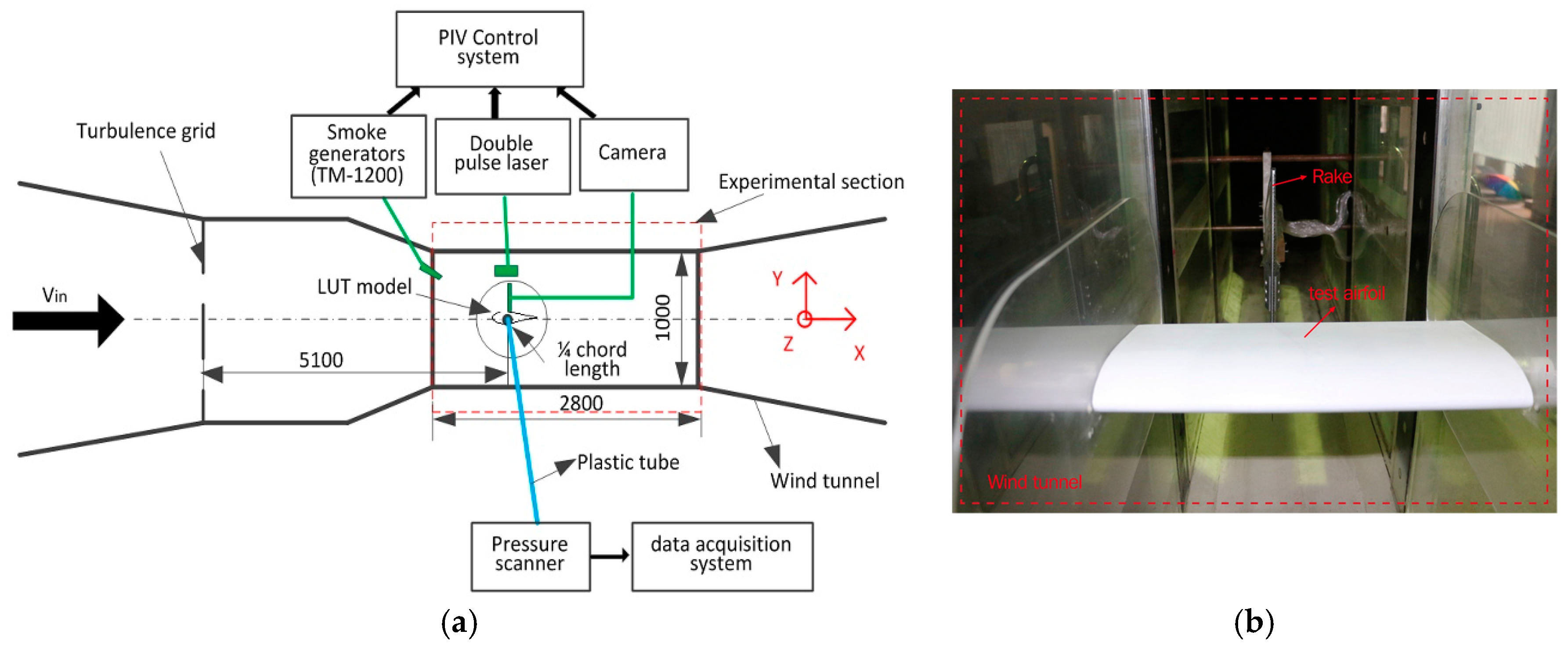
Wind tunnel tests were carried out in an open-circuit, closed-test-section, low-speed, and low-turbulence wind tunnel at the Northwestern Polytechnical University, as shown in Figure 5. The rectangular test section is 400 mm × 1000 mm, the length is 2800 mm, and the maximum wind speed is 70 m/s. The turbulence intensity is adjustable between 0.02% and 0.3% by changing the screen numbers. For the case of the empty test section in the stream direction with 12 layers of screens and a contraction ratio of 22.6, the turbulence intensity is 0.03%, 0.025%, and 0.02% at 12, 15, and 30 m/s freestream velocities, respectively [31], and the accuracy of the wind speed is less than ±3%.
The coordinate system of the wind tunnel is defined by the x-, y-, and z-axes, which represent the freestream, perpendicular direction, and span of the airfoil, respectively.

3.2. Test LUT Airfoil Model

In this study, the test LUT airfoil was designed by the authors. The cross-section width of the LUT model is the same as that specified above, the chord of the LUT is 200 mm, and the span is 400 mm. As shown in Figure 6, to investigate the aerodynamic performance of the LUT airfoil under a static condition, 50 pressure taps with a diameter of 0.7 mm are distributed on the LUT airfoil model, where the distribution average density of the pressure taps is 0.7:0.19:0.4 from the leading edge to the trailing edge of the LUT model.

3.3. Pressure Measurement and PIV (Particle Image Velocimetry) Devices

The pressure measurement devices include an electronic scanning measurement system (DSY104), pressure scanner (PSI9816), and angle of attack control mechanism. The accuracy of the pressure measurement and the PSI9816 pressure scanning are less than ±0.2% FS (Full Scale) and ±0.05% FS, respectively. The accuracy of the angle of attack control is ±2′. The Particle Image Velocimetry (PIV) systems include a double pulse laser with a maximum operating frequency of 15 Hz, a camera resolution of 2048 × 2048, a field range of 312 mm × 312 mm, and an image resolution of 152.66 µm/pixel. The tracer particles were produced by large smoke generators (TM-1200).
The pressure on the LUT airfoil surface is given by the pressure coefficient C p = ( P i P ) / ( 0.5 ρ V 2 ) , where P i is the pressure of the pressure tap i, P is the freestream static pressure, V is the freestream speed, and ρ is the air density. In this work, the drag coefficient was calculated by the wake investigation method. The wake rake had a height of 300 mm and was installed 0.9 c downstream from the test airfoil trailing edge. The calculation formula of the drag coefficient is:
c d = w a k e   r a k e   h e i g h t c x d ( y / c )
where y is the y-coordinate value of the total pressure tap for the wake rake, whose integral function is:
c x = 2 ( p 1 p ) 1 / γ ( p 01 p 0 ) ( γ 1 ) / γ [ 1 ( p 1 / p 01 ) ( γ 1 ) / γ 1 ( p / p 0 ) ( γ 1 ) / γ ] 0.5 [ ( 1 ( p / p 01 ) ( γ 1 ) / γ 1 ( p / p 0 ) ( γ 1 ) / γ ) 0.5 ] c x 0
where C x is the local drag coefficient of the total pressure tap for the wake rake, p 1 is the static pressure at the wake of the model, p is the freestream static pressure, p 01 is the total pressure of the wake rake, p 0 is the freestream total pressure, C x 0 is the C x arithmetic mean at the wake of the airfoil model, and γ is the specific heat ratio, which typically takes the value γ = 1.4 .
The lift coefficient C L was calculated by the relationship of the coordinate system, the drag coefficient C d , and the normal force coefficient C n :
C L = C n c o s α ( C d C n s i n α ) tan α
In the wind tunnel experiment, it was necessary to eliminate errors of measurement. Therefore, the pressure values of the pressure taps and the wake rake were referenced when the freestream velocity was 0 m/s and the angle of attack was 0°. Uncertainty analysis of the coefficients of both the lift and the drag was evaluated with the accuracy of the PSI9816 scanner.

4. Results and Discussion

4.1. Static LUT Airfoil Performance at Low Reynolds Number

In this section, the performance of the clean, static LUT airfoil is described for Re = 3 × 10⁵ and 5 × 10⁵ (these two low Reynolds numbers are suitable for the typical working environment of VAWTs), respectively.

4.1.1. Pressure Coefficient Distribution on the Surface for the LUT Airfoil

In Figure 7, the distribution of the pressure coefficients on the LUT airfoil surface is shown for some specific angles of attack at Re = 3 × 10⁵ and at Re = 5 × 10⁵. In this figure, the lines in black, red, and blue denoting the pressure coefficient (Cp) correspond to angles of attack of CL/Cd-max, CL-max, and post-stall, respectively.
In the case of Re = 3 × 10⁵, the LUT airfoil has a maximum lift coefficient of CL-max = 1.47 at an angle of attack of α = 14° and a maximum lift–drag ratio of CL/Cd-max = 64.4 at an angle of attack of α = 10°. After an angle of attack of α = 14°, the LUT airfoil starts to stall, and separation occurs on the suction surface at about 39% of the chord with an angle of attack of α = 16°. Therefore, the pressure coefficient on the suction surface of the LUT airfoil keeps a constant value from about 39% of the chord to the trailing edge. In the case of Re = 5 × 10⁵, the LUT airfoil has a maximum lift coefficient of CL-max = 1.5 at an angle of attack of α = 14° and a maximum lift–drag ratio of CL/Cd-max = 79.8 with an angle of attack of α = 10°. After an angle of attack α = 14°, the LUT airfoil starts to stall, and separation occurs on the suction surface at about 48% of the chord when the angle of attack is 16°. Moreover, after 48% of the chord, the pressure coefficient on the suction surface of the LUT airfoil keeps a constant value; that is, the LUT airfoil is fully stalled.
Comparing the cases of Re = 3 × 10⁵ and Re = 5 × 10⁵, the suction peak value increases and moves to the leading edge of the LUT airfoil with the increase in Re. This indicates that the region of adverse pressure gradient on the suction surface of the LUT airfoil is extended when Re = 5 × 10⁵. However, due to the effect of the turbulence, the flow separation is delayed [32]. Additionally, the pressure was not measured at large angles of attack due to the measuring range of the wake rake. In the future, the performance of the LUT needs to be studied at large angles of attack.
Figure 8 shows the changes in the pressure coefficient distribution with increasing angles of attack at different values of Re for the LUT airfoil. In the case of Re = 3 × 10⁵, the free transition position is located at 53% and 35% of the chord when the angle of attack is 0° and 8°, respectively. Until an angle of attack of α = 21°, the pressure of the upper surface from the leading edge to the trailing edge remains constant due to the complete separation of the flows on the upper surface; that is, leading-edge separation is occurring. Combined with Figure 7, the transition position on the upper surface slightly develops in the range 8° < α < 14° and is located at about 30% of the chord, indicating that the LUT is characterized by low drag, because the desirable pressure gradient exists at about 30% of the chord on the upper surface of the LUT airfoil [33], while the pressure coefficient on the lower surface is not obviously developed in the range 8° < α < 14°. Comparing the case of Re = 3 × 10⁵ to the case of Re = 5 × 10⁵, it is observed that the free transition position is more toward the leading edge with the increase in Re. An angle of attack of α = 8°, for example, results in a transition position located at about 29% of the chord when Re is 5 × 10⁵. In particular, in the case of Re = 5 × 10⁵, the pressure on the lower surface significantly drops at an angle of attack of α = 21°. This shows that obvious separation on the lower surface exists in the LUT airfoil at an angle of attack of α = 21°.
The above discussions indicate that the distribution of the pressure coefficient of the LUT is better before a stall angle of α = 14° for both the case of Re = 3 × 10⁵ and Re = 5 × 10⁵; moreover, the free transition position at about 30% chord almost keeps constant before the stall, it shows that the pressure distribution on the upper surface is steady between Re =3 × 10⁵ and Re =5 × 10⁵ for the LUT airfoil. However, in the case of Re = 5 × 10⁵, the pressure distribution on the lower surface is poor where the separation of the flows is obvious after a stall angle of α = 14°.

4.1.2. Lift Coefficient of the LUT Airfoil

As shown in Figure 9, we investigated the relationship between the lift coefficient and the angles of attack at two Reynolds numbers, Re = 3 × 10⁵ and Re = 5 × 10⁵, obtained from Equation (17). In this Figure, the lines in black and red of the lift coefficient correspond to the results of the experiment and the numerical simulation (design results) for the LUT airfoil, respectively. In the case of Re = 3 × 10⁵, the lift coefficient of the LUT airfoil linearly increases in the extending direction of the angles of attack from α = −9° to α = 12° (this region is called the linear region). At an angle of attack of α = 14°, the lift coefficient reaches its maximum value at CL-max = 1.47, and then the curve of the lift coefficient displays a gentle downward trend until an angle of attack of α = 21°, a phenomenon called a stall. This indicates that the LUT airfoil has good stall performance.
In the case of Re = 5 × 10⁵, the trend for the lift coefficient curve is the same as that of Re = 3 × 10⁵ at the angles of attack from α = −9° to α = 12°. However, the maximum lift coefficient CL-max is 1.5 at an angle of attack of α = 14°. Comparing the results of the experiment to the results of the numerical simulation (design results), in the linearly increasing areas, the values of the lift coefficient are almost the same for the two values of Re. However, after the stall angle of attack, the values of the lift coefficient for Re = 5 × 10⁵ have a slight difference and are larger than the value of the lift coefficient for Re = 3 × 10⁵. While the numerical simulation results are larger than those of the experiment, these differences are very small. Therefore, the results of the numerical simulation (design results) are in agreement with the results of the experiment reported in this paper.

4.1.3. Drag Coefficient of the LUT Airfoil

The relationship between the drag coefficient and the angles of attack are displayed for the two Reynolds numbers, Re = 3 × 10⁵ and Re = 5 × 10⁵, in Figure 10, where the drag coefficient was obtained via Equations (15) and (16).
In Figure 10, the lines in black and red of the drag coefficient correspond to the experimental results and the numerical simulation results (design results), respectively. In the cases of Re = 3 × 10⁵ and Re = 5 × 10⁵, the values of the drag coefficient are smaller and remain almost constant in the range −10° < α < 10°, because the most attached flow is on the surface of the LUT airfoil. The numerical simulation results agree with the experimental results in this region. However, the values of the drag coefficient increase rapidly when the angle of attack is greater than α = 13° or less than α = −10°. The results of the experiment and the numerical simulation show a slight difference, but these errors are acceptable. Therefore, the results of the numerical simulation (design results) are in agreement with the results of the experiment reported in this paper.
Figure 9 and Figure 10 demonstrate that the results of the experiment agree with the results of the numerical simulation at low angles of attack. However, at high angles of attack where the flow separation occurs, there are some slight differences between the results of the experiment and the numerical simulation. On the one hand, the characteristics of the lift and drag of the LUT airfoil are obtained through integral surface pressure in this experiment, while the results of the numerical simulation with the SST k-ω turbulence model are acquired with solving the Reynolds-averaged Navier–Stokes equation; on the other hand, even though the current numerical methods have been greatly improved, for example, the predicted result of the SST k-ω turbulence model is accurate, but the SST k-ω turbulence model cannot completely solve the turbulence problem [34,35]. In addition, the wall of the LUT model is infinitely smooth in the numerical simulation, but in the current experiment, although the surface of the LUT model has very low roughness, the roughness of the surface is limited. Therefore, the results of the experiment and the numerical simulation have some differences in the region of the flow separation, while the results of the experiment and the numerical simulation are almost the same at low angles of attack.
Additionally, the maximum lift coefficient of the LUT airfoil has slow change with the increase in Re from Re =3 × 10⁵ to Re = 5 × 10⁵.

4.1.4. Lift–Drag Ratios of the LUT Airfoil

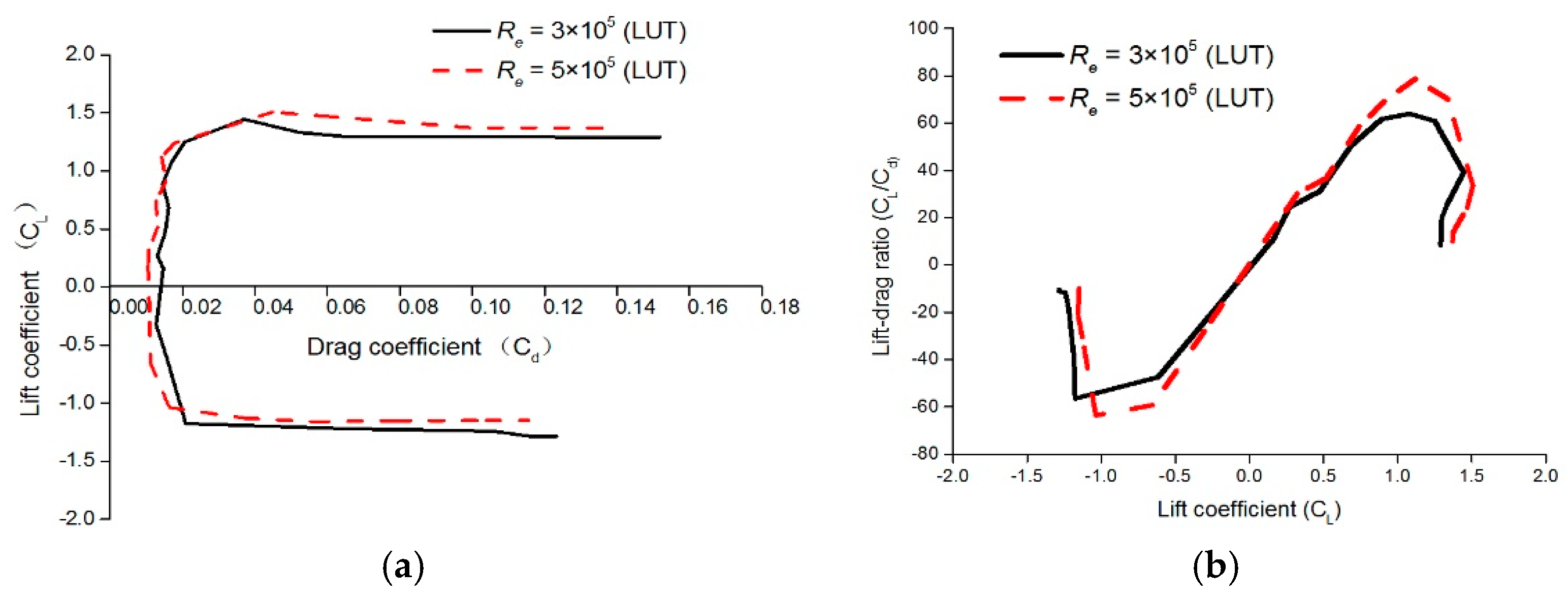
Figure 11a presents the lift coefficient versus the drag coefficient at different values of Re for the LUT airfoil, where the lift coefficient and drag coefficient are described in and were obtained according to Section 4.1.1 and Section 4.1.2. The lines in black and red of the lift–drag ratios correspond to Re = 3 × 10⁵ and Re = 5 × 10⁵, respectively. The results show that the LUT airfoil has the maximum lift–drag ratio CL/Cd-max = 64.4 at an angle of attack of α = 10° when Re = 3 × 10⁵, and it has the maximum lift–drag ratio CL/Cd-max = 79.8 at an angle of attack of α = 10° when Re = 5 × 10⁵. Moreover, combined with Figure 10, the lift–drag ratios linearly increase in the range −10° < α < 10°. Therefore, the LUT airfoil presents a wider drag bucket, which is a desired characteristic for the airfoil of VAWTs due to the law of motion of the VAWTs [19]. Figure 11b shows the lift–drag ratios versus the lift coefficients, where the colors of the lines have the same meaning as in Figure 11a. The lift–drag ratios of the LUT increase almost linearly with the increase in the lift coefficient in the range −1 ≤ CL ≤ 1.25.
In Figure 12, the flow separation on the surface of the LUT is displayed at different angles of attack when the Re is 3 × 10⁵, measured using PIV technology. Figure 12 shows that the separation point gradually moves from the trailing edge to the leading edge with the increase in the angle of attack, which is consistent with the results in Figure 7 and Figure 8. Moreover, the separation vortex becomes high due to the gradual flow separation. Especially at the angle of attack α = 22° in Figure 12g, the leading-edge separation results in the formation of the wake vortex and the detached vortex. At this moment, the pressure distribution on the upper surface of the LUT airfoil keeps a constant value, as shown in Figure 8a. Figure 12d–f displays the development of the flow separation on the upper surface of the LUT airfoil, which results in decreasing pressure on the upper surface of the airfoil, as shown in Figure 7a. However, the development of the vortices on the upper surface of the LUT airfoil are slow; combined with Figure 8a, it indicates that the LUT airfoil has good stall performance. Meanwhile, the changes in flow separation on the lower surface of the LUT airfoil are presented in Figure 12a–c when the angle of attack is a negative value. The pressure distribution on the LUT airfoil surface at a negative angle of attack is shown in Figure 8. However, due to the limited field range of the PIV here, it is difficult to observe the development of the wake vortices. Meanwhile, at a large negative angle of attack, the flow separation on the lower surface is obvious, and the separation point on the lower surface moves toward the leading edge with increasing angles of attack.
However, because the placement of the PIV equipment was only convenient for photographing the upper surface of the LUT model, the phenomenon of flow separation was not obviously surveyed. Consequently, we could only survey the vortices near the trailing edge of the LUT.
Table 1 shows the main geometrical and aerodynamic parameters of a part of the commonly used and special-purpose airfoils for straight-bladed VAWTs when Re is 3 × 10⁵ and 5 × 10⁵. In addition, the MI-VAWT1 airfoil [9] is also a dedicated airfoil for VAWTs; it has a 21% thickness and 0.44% camber. Compared with the results for Table 1, the geometrical parameters of the LUT airfoil balance the strength of the blade and the aerodynamic performance for a VAWTs with the LUT airfoil. Especially, the LUT airfoil performs better in the maximum lift coefficient and the maximum lift–drag ratios at a low Re, it is very important, because VAWTs typically operate at a low Re [19]. However, the stall angle of attack of the LUT airfoil is smaller than that of the airfoil in Table 1.

5. Conclusions

In this study, we designed an asymmetrical airfoil for straight-bladed VAWTs based on the law of motion of the VAWTs by employing the SQP optimization method; we called this design the LUT airfoil. Meanwhile, the aerodynamic performance of the LUT airfoil was investigated at two Reynolds numbers, 3 × 10⁵ and 5 × 10⁵, under the conditions of a low-speed, low-turbulence wind tunnel at the Northwestern Polytechnical University, China; the flow field around the LUT airfoil was observed by PIV technology.
The LUT airfoil has a 20.77% moderate thickness and 1.11% moderate camber. Moreover, the position of the maximum camber is close to the trailing edge, which forms a trailing-edge loading to improve the efficient lift of the LUT airfoil. The maximum thickness of the LUT airfoil is achieved by restricting the thickness of the upper surface while adding the thickness of the lower surface. It is conducive to delay flow separation on the upper surface. Moreover, the moderate thickness helps to ensure the structural strength of the blade and to improve the performance of VAWTs with the LUT airfoil at high tip speed ratio.
Ultimately, the main objectives of achieving a higher maximum lift coefficient, higher maximum lift–drag coefficient, and gentle stall characteristics were achieved. Compared with the airfoil commonly used for VAWTs, the LUT airfoil displays a better aerodynamic performance at a low Re. Additionally, the maximum lift coefficient of the LUT airfoil is steady with the increase in Re between 3 × 10⁵ and 5 × 10⁵. The LUT airfoil retains the desirable characteristic of low drag over a wide range of angles of attack in the range −10° < α < 10°, that is, the LUT airfoil has a wide drag bucket. The distribution of the pressure coefficient agrees with the results obtained using PIV. Theoretically, due to the larger 3.84% leading-edge radius and other geometric features, the LUT airfoil can reduce the sensitivity to roughness.
In future work, the LUT airfoil’s sensitivity to roughness and noise level will be tested by wind tunnel experiments.

Author Contributions

Methodology, S.L., Y.L. and Q.W.; Writing—Original Draft Preparation, S.L. and X.Z.; and Writing—Review and Editing, Y.L., C.Y., D.L., W.Z. and T.W.

Funding

The authors acknowledge funding from the Natural Science Foundation of GANSU (grant No. 1508RJYA098), the National Natural Science Foundation of China (No. 51506088 and No. 51766009), and the National Basic Research Program of China (No. 2014CB046201)

Acknowledgments

The authors would like to acknowledge and thank the Natural Science Foundation of GANSU (grant No. 1508RJYA098); the National Natural Science Foundation of China (No. 51506088 and No. 51766009); the National Basic Research Program of China (No. 2014CB046201); the people who provided many good suggestions for this paper; and the Northwestern Polytechnical University and China Aerodynamics Research and Development Center for providing the experiment instruments and wind tunnel.

Conflicts of Interest

The authors declare no conflict of interest.

Nomenclature

H-VAWTH-type Vertical Axis Wind Turbines
VAWTVertical Axis Wind Turbines
HAWTHorizontal Axis Wind Turbines
LUTThe name of the newly designed airfoil (Lanzhou University of Technology)
DTUTechnical University of Denmark
SSTShear Stress Transport
ReReynolds number
αangle of attack, °
θazimuthal angle, °
ωrotational speed of the wind turbine, rad/s
Vinfreestream velocity, m/s
Rrotor radius, m
Cairfoil chord length, mm
SQPSequential Quadratic Programming
σpenalty factor
CL/Cdlift–drag ratios
CLlift coefficient
Cddrag coefficient
r0leading-edge radius
CpPressure coefficient
PIVParticle Image Velocimetry
FSFull Scale

Appendix A

Figure A1. The optimization flow of the airfoil profile based on the SQP method.
Applsci 08 02266 g0a1

References

  1. Ho, A.; Mbistrova, A.; Corbetta, G. The European Offshore Wind Industry-Key Trends and Statistics 2015; Technical Report; European Wind Energy Association: Brussels, Belgium, February 2016. [Google Scholar]
  2. Battisti, L.; Benini, E.; Brighenti, A.; Dell’Anna, S.; Raciti Castelli, M. Small wind turbine effectiveness in the urban environment. Renew. Energy 2018, 129, 102–113. [Google Scholar] [CrossRef]
  3. Guo, Y.; Liu, L.; Gao, X.; Xu, W. Aerodynamics and Motion Performance of the H-Type Floating Vertical Axis Wind Turbine. Appl. Sci. 2018, 8, 262. [Google Scholar] [CrossRef]
  4. Kumar, R.; Raahemifar, K.; Fung, A.S. A critical review of vertical axis wind turbines for urban applications. Renew. Sustain. Energy Rev. 2018, 89, 281–291. [Google Scholar] [CrossRef]
  5. Li, Q.; Maeda, T.; Kamada, Y.; Ogasawara, T.; Nakai, A.; Kasuya, T. Investigation of power performance and wake on a straight-bladed vertical axis wind turbine with field experiments. Energy 2017, 141, 1113–1123. [Google Scholar] [CrossRef]
  6. Aslam Bhutta, M.M.; Hayat, N.; Farooq, A.U.; Ali, Z.; Jamil, S.R.; Hussain, Z. Vertical axis wind turbine—A review of various configurations and design techniques. Renew. Sustain. Energy Rev. 2012, 16, 1926–1939. [Google Scholar] [CrossRef]
  7. Sutherland, H.J.; Berg, D.E.; Ashwill, T.D. A Retrospective of VAWT Technology; Technical Report SAND2012-0304; Sandia National Laboratories: Albuquerque, NM, USA, January 2012.
  8. Kanyako, F.; Janajreh, I. Numerical Investigation of Four Commonly Used Airfoils for Vertical Axis Wind Turbine. In ICREGA’14-Renewable Energy: Generation and Application; Hamdan, M., Hejase, H., Noura, H., Fardoun, A., Eds.; Springer: Cham, Switzerland, 2014; pp. 443–454. [Google Scholar] [CrossRef]
  9. Islam, M. Analysis of Fixed-Pitch Straight-Bladed VAWT with Asymmetric Airfoils. Ph.D. Thesis, University of Windsor, Windsor, ON, Canada, 2008. [Google Scholar]
  10. Kirke, B.K. Evaluation of Self-Starting Vertical Axis Wind Turbines for Stand-Alone Appllications. Ph.D. Thesis, Griffith University, Brisbane, Australia, 1998. [Google Scholar]
  11. Rainbird, J.M.; Bianchini, A.; Balduzzi, F.; Peiró, J.; Graham, J.M.R.; Ferrara, G.; Ferrari, L. On the influence of virtual camber effect on airfoil polars for use in simulations of Darrieus wind turbines. Energy Convers. Manag. 2015, 106, 373–384. [Google Scholar] [CrossRef]
  12. Mohamed, M.H.; Ali, A.M.; Hafiz, A.A. CFD analysis for H-rotor Darrieus turbine as a low speed wind energy converter. Eng. Sci. Technol. Int. J. 2015, 18, 1–13. [Google Scholar] [CrossRef]
  13. Carrigan, T.J.; Dennis, B.H.; Han, Z.X.; Wang, B.P. Aerodynamic Shape Optimization of a Vertical-Axis Wind Turbine Using Differential Evolution. ISRN Renew. Energy 2012, 2012, 1–16. [Google Scholar] [CrossRef] [Green Version]
  14. Asr, M.T.; Nezhad, E.Z.; Mustapha, F.; Wiriadidjaja, S. Study on start-up characteristics of H-Darrieus vertical axis wind turbines comprising NACA 4-digit series blade airfoils. Energy 2016, 112, 528–537. [Google Scholar] [CrossRef]
  15. Chen, J.; Chen, L.; Xu, H.; Yang, H.; Ye, C.; Liu, D. Performance improvement of a vertical axis wind turbine by comprehensive assessment of an airfoil family. Energy 2016, 114, 318–331. [Google Scholar] [CrossRef]
  16. Sheldahl, R.E.; Klimas, P.C. Aerodynamic Characteristics of Seven Sysmmetrical Airfoil Sections Through 180-Degree Angle of Attack for Use in Aerodynamic Analysis of Vertical Axis Wind Turbines; Technical Report SAND80-2114; Sandia National Laboratories: Albuquerque, NM, USA, March 1981.
  17. Klimas, P.C. Tailored Airfoils for Vertical Axis Wind Turbines; Technical Report SAND84-1062; Sandia National Laboratories: Albuquerque, NM, USA, November 1984.
  18. Islam, M.; Fartaj, A.; Carriveau, R. Design analysis of a smaller-capacity straight-bladed VAWT with an asymmetric airfoil. Int. J. Sustain. Energy 2011, 30, 179–192. [Google Scholar] [CrossRef]
  19. Islam, M.; Ting, D.S.-K.; Fartaj, A. Desirable Airfoil Features for Smaller-Capacity Straight-Bladed VAWT. Wind Eng. 2007, 31, 165–196. [Google Scholar] [CrossRef]
  20. Ferreira, C.S.; Geurts, B. Aerofoil optimization for vertical-axis wind turbines. Wind Energy 2015, 18, 1371–1385. [Google Scholar] [CrossRef]
  21. Ragni, D.; Ferreira, C.S.; Correale, G. Experimental investigation of an optimized airfoil for vertical-axis wind turbines. Wind Energy 2015, 18, 1629–1643. [Google Scholar] [CrossRef]
  22. Batista, N.C.; Melício, R.; Mendes, V.M.F.; Calderón, M.; Ramiro, A. On a self-start Darrieus wind turbine: Blade design and field tests. Renew. Sustain. Energy Rev. 2015, 52, 508–522. [Google Scholar] [CrossRef]
  23. Bedon, G.; Betta, S.D.; Benini, E. Performance-optimized airfoil for Darrieus wind turbines. Renew. Energy 2016, 94, 328–340. [Google Scholar] [CrossRef]
  24. Hand, B.; Kelly, G.; Cashman, A. Numerical simulation of a vertical axis wind turbine airfoil experiencing dynamic stall at high Reynolds numbers. Comput. Fluids 2017, 149, 12–30. [Google Scholar] [CrossRef]
  25. Sargent, R.W.H.; Ding, M. A New SQP Algorithm for Large-Scale Nonlinear Programming. SIAM J. Optim. 2001, 11, 716–747. [Google Scholar] [CrossRef]
  26. Andrei, N. Sequential Quadratic Programming Continuous (SQP). In Nonlinear Optimization for Engineering Applications in GAMS Technology, 1st ed.; Springer: Cham, Switzerland, 2017; Volume 121, pp. 269–288. ISBN 978-3-319-58355-6. [Google Scholar]
  27. Howell, R.; Qin, N.; Edwards, J.; Durrani, N. Wind tunnel and numerical study of a small vertical axis wind turbine. Renew. Energy 2010, 35, 412–422. [Google Scholar] [CrossRef] [Green Version]
  28. Airfoil Tools. Available online: http://airfoiltools.com/ (accessed on 1 September 2018).
  29. Timmer, W.A.; Van Rooij, R.P.J.O.M. Summary of the Delft University Wind Turbine Dedicated Airfoils. J. Sol. Energy Eng. 2003, 125, 488–496. [Google Scholar] [CrossRef]
  30. Fuglsang, P.; Bak, C. Development of the Risø wind turbine airfoils. Wind Energy 2004, 7, 145–162. [Google Scholar] [CrossRef]
  31. Meng, X.; Hu, H.; Yan, X.; Liu, F.; Luo, S. Lift improvements using duty-cycled plasma actuation at low Reynolds numbers. Aerosp. Sci. Technol. 2018, 72, 123–133. [Google Scholar] [CrossRef]
  32. Anderson, J.D. Fundamentals of Aerodynamics, 5th ed.; McGraw-Hill Education: New York, NY, USA, 2011; ISBN 9780073398105. [Google Scholar]
  33. Somers, D.M. Design and Experimental Results for the S825 Airfoil Period of Performance: 1998–1999 Design and Experimental Results for the S825 Airfoil; Technical Report NREL/SR-500-36346; National Renewable Energy Laboratory: Golden, CO, USA, 2005.
  34. Balduzzi, F.; Bianchini, A.; Maleci, R.; Ferrara, G.; Ferrari, L. Critical issues in the CFD simulation of Darrieus wind turbines. Renew. Energy 2016, 85, 419–435. [Google Scholar] [CrossRef]
  35. Zhang, X.; Wang, G.; Zhang, M.; Liu, H.; Li, W. Numerical study of the aerodynamic performance of blunt trailing-edge airfoil considering the sensitive roughness height. Int. J. Hydrogen Energy 2017, 42, 18252–18262. [Google Scholar] [CrossRef]
Figure 1. Schematic of an H-type Vertical Axis Wind Turbines (H-VAWT): (a) 3D schematic; and (b) 2D cross-section. The rotor of the H-VAWT turns counterclockwise; the azimuth angle θ is defined to help describe the active conditions of an H-VAWT. R is the radius of the rotor in units of mm. ω is the rotation angular velocity of the rotor in units of rad/s.
Applsci 08 02266 g001
Figure 2. Scheme of the geometry and boundary conditions for the numerical simulation: (a) The semicircular far field is set as a velocity inlet located at 12.5 c (c is chord length) from the trailing edge of the airfoil, while the outlet condition is the pressure outlet located at 20 c from the trailing edge of the airfoil. (b) The boundary layer consists of 40 cell layers: the height of first layer is 1 × 10⁻⁶; the growth rate of the grid is 1.05 in the boundary layer.
Applsci 08 02266 g002
Figure 3. Airfoil optimization and convergence process. The process of the optimization was from 0 to 6, where the 0 and 6 represent the NACA 0018 airfoil and Lanzhou University of Technology (LUT) airfoil, respectively. (a) The constraint conditions were the minimum Cd/CL, thickness, and camber of the airfoil for the LUT airfoil. (b) The maximum lift–drag ratio of the NACA 0018 is 65.8 at an angle of attack of 9.25° [28]. In this Figure, the Re is 5 × 10⁵.
Applsci 08 02266 g003
Figure 4. The profiles of the three airfoils. The profiles of the NACA 0018 and DU06-W-200 models come from the material specified on the website [28]. As shown in this Figure, the marks in black, red, and blue represent the profiles of the LUT, DU06-W-200, and NACA 0018 airfoils, respectively.
Applsci 08 02266 g004
Figure 5. Experimental scheme of the wind tunnel and the testing of the LUT airfoil: (a) schematic of the wind tunnel and the experimental devices; and (b) experiment section. The cross-section of the wind tunnel is 400 mm × 1000 mm and the length is 2800 mm.
Applsci 08 02266 g005
Figure 6. The profile and the distribution of the pressure taps for the test LUT airfoil. The total number of pressure taps is 50 on the surface of the airfoil, and the density of the pressure taps is closely distributed at the leading edge and the trailing edge of the test LUT airfoil.
Applsci 08 02266 g006
Figure 7. Pressure coefficient distribution of the LUT airfoil: (a) the case of Re = 3 × 10⁵; and (b) the case of Re = 5 × 10⁵. The data were measured when the surface of the LUT airfoil was clean. The lines in black, red, and blue show the pressure coefficients corresponding to angles of attack of CL/Cd-max, CL-max, and post-stall, respectively.
Applsci 08 02266 g007
Figure 8. Pressure distribution for the LUT airfoil: (a) the case of Re = 3 × 10⁵; and (b) the case of Re = 5 × 10⁵. The data were measured when the surface of the LUT airfoil was clean. As shown in this figure, the lines in black, red, blue, and pink show the pressure coefficients corresponding to the angles α = −4°, α = 0°, α = 8°, and α = 21°, respectively.
Applsci 08 02266 g008
Figure 9. Lift coefficient for the LUT airfoil at different values of Re: (a) the case of Re = 3 × 10⁵; and (b) the case of Re = 5 × 10⁵. The lines in black and red of the lift coefficient correspond to the experimental results and the numerical simulation results, respectively.
Applsci 08 02266 g009
Figure 10. Drag coefficient for the LUT airfoil at different values of Re: (a) the case of Re = 3 × 10⁵; and (b) the case of Re = 5 × 10⁵. The lines in black and red of the drag coefficient correspond to the experimental results and the numerical simulation results, respectively.
Applsci 08 02266 g010
Figure 11. The characteristics of lift–drag ratios for the LUT airfoil at different values of Re: (a) the relationship between the lift coefficient and the drag coefficient; and (b) the relationship between lift–drag ratios and the lift coefficient. The lines in black and red of the lift–drag ratios correspond to Re = 3 × 10⁵ and Re = 5 × 10⁵, respectively.
Applsci 08 02266 g011
Figure 12. Contours of the velocity and stream lines at different angles of attack: (ag) the contours of the velocity at different angles of attack. This figure shows the transient contours from the angle of attack α = −20° to the angle of attack α = 22° at Re = 3 × 10⁵. However, only the varying velocity on the upper surface of the LUT and the larger vortex are captured in this figure due to the picture being limited by the ability of the Particle Image Velocimetry (PIV) equipment.
Applsci 08 02266 g012
Table 1. Main geometrical parameters and aerodynamic parameters of a part of commonly used airfoils for straight-bladed VAWTs.
AirfoilRe (1 × 10⁵)Max. Thickness(x/c) Max. ThicknessMax. Camber(x/c) Max. CamberRadius Leading Edge (r0/c)Max. CL/Cd (α)Max. CL (α)
Du06-W-200 [28]319.8%31.1%0.5%84.6%1.7442%58.05 (9.75°)1.4153 (16.75°)
571.5 (9.5°)1.4384 (18°)
NACA0018 [28]318%30%003.1017%57.09 (8.25°)1.24 (18.75)
565.8 (9.25°)1.2624 (16.5°)
NACA0015 [28]515%30%002.3742%66.43 (7.5°)1.2731 (16.75°)
DU12W262 [21]-26.2%37%-----
AIR013 [20]-34.9%-2.29%-7.8%--
Note: “-” indicates that the data of the corresponding locations are not presented in the literature.