Article

A Requirement Engineering Framework for Electric Motors Development

Faculty of Engineering, Mondragon Unibertsitatea, 20500 Mondragon, Spain
*
Author to whom correspondence should be addressed.
Appl. Sci. 2018, 8(12), 2391; https://doi.org/10.3390/app8122391
Submission received: 30 October 2018 / Revised: 19 November 2018 / Accepted: 22 November 2018 / Published: 26 November 2018
(This article belongs to the Section Energy Science and Technology)

Abstract

:
The applications using electric motors have increased in the last decade. Some of these applications encounter the need for tailor-made motors that must meet demanding requirements. Therefore, the specification stage of an electric motor is a critical part of its development. If this stage is properly addressed, then future failures in the development process can be avoided. This paper presents a requirement engineering framework to support small-medium electric motors designers/manufacturers with the development of their product. The framework identifies the stakeholders and the tasks that they should undertake to finish a successful requirements specification stage. The framework is made from the designer/manufacturer’s perspective and it emphasizes the derivation of specialized requirements (lower-level). The result of the framework is well-defined requirements that form the design requirements specification of the motor that leads to the beginning of the design stage.

1. Introduction

The specification stage is the basis for the efficient development of any product. This stage, if properly managed, avoids future failures in the development process [1]. The first step in designing or manufacturing an electric motor is to specify its requirements explicitly. Large manufacturers usually create guidelines or custom-forms with the specifications customers should take into account. In this way, they can supply a motor fitting their application (either from stock or tailor-made) [2,3]. In [4], it is stated that a motor technical specification should define performance requirements, identify reliability indicators describing the environment in which it operates, and state maintenance conditions to help the user with its management plan. [5] presents some factors that affect decisions making when purchasing motors: product quality and reliability, price, service quality, brand reputation, energy efficiency, lead times, and policies. The weight of each factor varies according to the perspective of the end-users, for example, original equipment manufacturers (OEMs) or distributors.
Literature offers general requirement engineering frameworks [6] as well as specialized in different disciplines [7,8,9]. However, there is a lack of specialized frameworks for electric motor development. Usually, literature regarding electric motors starts with well-defined requirements, so the phase of the specification stage is not mentioned.
Moreover, large electric motor manufacturers have enough economic resources to develop new products and to automate their plants and processes. Manufacturers from emerging countries offer low-cost competitive products. In this context, small-medium size electric motors design/manufacturing companies have survived due to their offer of specialized tailor-made products [10].
Therefore, to support these companies to cope with the specification stage, this paper aims to contribute to the field of requirement engineering for electric motors by providing a new macro-process framework with a systematic approach derived from the experience of the authors. The framework is made from the designer/manufacturer’s perspective and it emphasizes the derivation of requirements from a higher level to lower level requirements.
The authors have used and proven the approach herein described on several industrial projects. Furthermore, a use case example is presented to demonstrate the use of the framework.
The remainder of this paper is structured as follows. Section 2 overviews current requirements engineering approaches on electric motors. In Section 3, the framework is presented. Section 4 shows a use case example on deriving electromagnetic requirements for an elevator application. Finally, Section 5 discussed the work.

2. Current Requirement Engineering Approaches on Electric Motors

This section provides a comparison of requirement engineering approaches available on literature, addressing implicitly or explicitly the specification stage on electric motors. As mentioned earlier, there are some factors that affect the decision making on selecting motors being dependent on the perspective of customers or end-users. Therefore, the definition of requirements is application-dependent. For this reason, the authors of this paper classify the requirement engineering approaches as off-the-shelf and tailor-made solutions based on the two types of solutions that manufacturers can offer. The approaches are described from the developer’s perspective.

2.1. Off-the-Shelf Solutions Approach

Standards, such as IEC in Europe and NEMA in the United States, define general characteristics and performance tests of electric motors to facilitate their interchangeability. In addition, regulations/policies/directives define mandatory requirements leading to minimum energy performance standards (MEPS). Large manufacturers have developed off-the-shelf motors satisfying these standards allowing for a simpler and convenient motor selection for customers. In this case, the specification stage is a process of sales-purchase transaction of equipment. Classic ways to handle the specification stage are either to make available the datasheets of motors in stock or to provide forms (e.g., spreadsheet) with requirements fields that the customers must fill to present motor solutions [2,3,11]. Due to the interest of customers in factors, such as efficiency, reliability, and quality of the product [5], some manufacturers offer support to find a solution, which best fit their application, from their catalog. Customers may demand factory acceptance tests or quality certificates of the motors. However, the interaction among the stakeholders is typically a sales-customer relationship.

2.2. Tailor-Made Solutions Approach

Applications demanding customized-solutions of electric motors are increasing, common examples are the automotive and aerospace industry. Automotive manufacturers are even improving production processes to include electric motors in their value chain [12]. For tailor-made solutions, design requirements are derived through a detailed analysis, where both, client and designer/manufacturer are involved during the development process or life cycle of the motor. Depending on the case, an efficient specification stage may involve different domain experts to obtain the requirements. In [13], the author acknowledges the need to consider the point of view of all stakeholders for an integrated design approach. In [14], the author states the objective of the specifications is to translate the function of the driven-load into the terms of electric drives, providing a classification of characteristics of the system with examples. An application example demanding special requirements on electric motors is presented in [15].
In conclusion, from the literature review, it can be stated that there is not a systematic approach that defines the iteration among the different stakeholders that are involved in the requirement development process. At the same time, there is a lack of a systematic organization among the different requirements. To have a successful design without spending time on redesign tasks, it is highly recommended that different technical experts check in detail the feasibility of all requirements that are associated with their engineering domain. The technical reviewing can become hard to do if the process is not well approached. Typically, an unwanted result is the waste of time due to several re-analysis of the same requirement. Regarding electric motor design, the absence of requirement engineering with a systematic approach in the technical literature is mainly due to the fact that the requirements are presented—as given—with all the details predefined. This level of detail is hard to achieve in tailor-made solutions and is recommended to have a collaborative approach between the integrator and developer to define accurate and realistic requirements. Therefore, this paper presents a requirement engineering framework with a systematic approach describing a collaborative iteration among the stakeholders (eMotor integrator and eMotor developer) as a contribution to the lack of literature regarding this problem.

3. The Framework

In this section, the requirements framework is presented through the Systems Modeling Language (SysML) diagrams. It is broken down into five subsections: the stakeholders, classification of requirements package, activities, qualification of requirements, and tools. This requirement engineering framework aims to provide a specialized guideline to electric motor developers. Users may adjust, add, or skip any aspect of the framework to suit their project.

3.1. Stakeholders

The framework identifies two stakeholders, the integrator and the motor developer (designer/manufacturer). The integrator is the actor or actors that are interested in integrating the developed electric motor into the application for which it is designed. The integrator is considered the expert in the particular application; in other words, the integrator has a complete knowledge in the application system, but usually no expertise regarding electric motor design. The electric motor developer is the actor or actors responsible for the design/manufacturing of the motor satisfying the integrators’ requirements. The generalization of the latter actor is shown in Figure 1. This generalization shows that the developer can be represented by several actors with expertise in the different fields that are involved in the electric motor development process. The framework is made from the electric motor developer’s perspective.
The use case diagram shown in Figure 2 illustrates both actors with their implications within the context of this framework. In summary, it can be seen that the integrator defines the motor requirements from the application point of view, which includes a clear description or explanation of the application system. On the other hand, the electric motor developer must derive the integrators’ requirements into the different technical domains to develop the motor following an efficient process. This includes the process of interpreting each requirement; it may also include an engineering assessment of the application system, i.e., to model the application system to obtain its operating characteristics. Finally, both actors are involved in the approval, editions, or rejections of requirements during the entire development process.

3.2. Classification of Requirements Package

In order to facilitate the requirements analysis, the proposal is to divide the requirements into three general packages representing different levels, as it is shown in Figure 3 and described below.
  • Application essential requirements from the integrator. The requirements contained in the initial specification are classified into different non-functional groups, such as operability, serviceability, reliability, comfort, special, and standards/regulations/policies requirements packages. The satisfaction of these requirements ensures that the motor correct performance in the system application.
  • Technical derived requirements. These are derived or copied from the essential requirements into the different disciplines: mechanical, electrical, control, manufacturing engineering, also additional requirements and cross-domain objectives. The satisfaction of these requirements ensures the correct design and performance of the motor during the development process and the system application integration tests.
  • Specific-domain derived requirements. These are derived or copied from the technical derived requirements into the different domains that are involved in the motor development; herein emphasizing: structural, electromagnetic, vibro-acoustics, insulation, thermal, and electromagnetic compatibility (EMC). The satisfaction of these requirements ensures the correct design and performance of the motor during the development process.
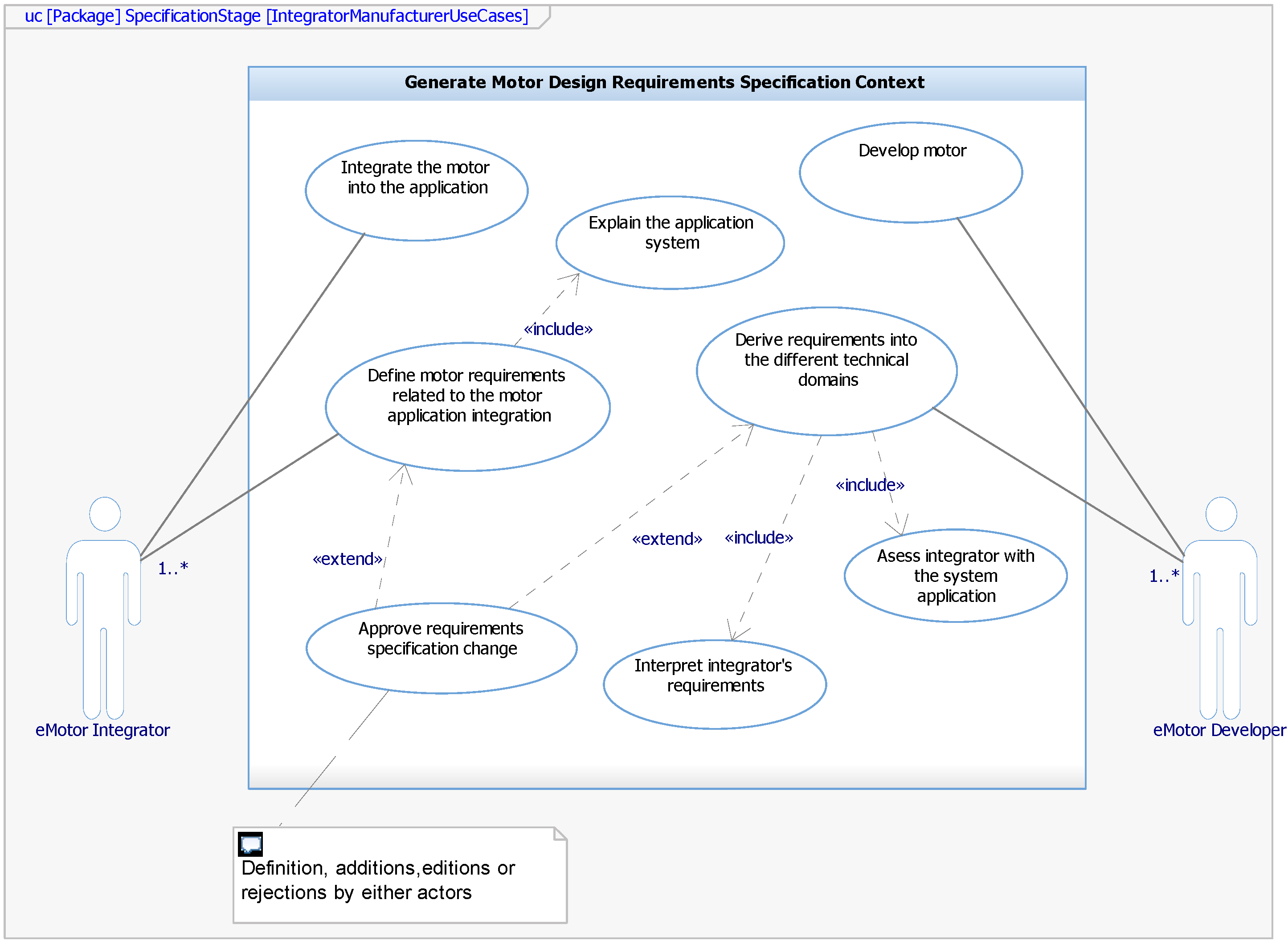
Table 1 shows examples of requirements that fit on each group. However, the developer (experts in their field) should decide this internal classification. The essential requirements may be found in compound form in the initial requirements specifications. If this is the case, to better define them, these ought to be decomposed into more requirements. Some may be implicit; nevertheless, if an analysis is carried out, these should be categorized as derived and put inside one of the technical derived disciplines group. Regarding the domain-specific requirements, these are the ones that each domain need to design its respective partition. Some requirements may only be copied from a higher-level group.

3.3. Activities

The main activities of the proposed framework are shown in Figure 4. The process starts when the integrator makes and handles the requirements specification of the application to the developer usually with explicit or implicit objectives. In this document, the regulations/standards/policies to be taken into account are also commonly included. After a quick inspection, if the developer finds the need for any information not available in order to start the requirement analysis, a request for information must be made. Otherwise, the next activity is to analyze the application requirements. Generally, in this first stage, ambiguities are found, these must be avoided and well defined with the approval of both parts. For instance, “the motor must be highly efficient”. This statement is not quantifiable; therefore, a measurable quantity should be assigned either by a standard nomenclature (E2, E3, E4) or a restriction (>80%). The activity, analyze the application requirements, is composed of the different actions that are shown in Figure 5. First, the developer should verify all the requirements and objectives from the integrator are within the application context in order to state the changes or to avoid additional work. Once this is done the requirements must be classified into the different generalized non-functional groups that are described in Section 3.2.
The next activity is to verify the technical viability of the requirements that contain the actions shown in Figure 6. To verify the technical viability of the requirements is necessary to derive requirements into the different disciplines involved in the project, these disciplines were described in Section 3.2. The analysis to derive requirements into the different disciplines is application dependent. This process may involve meetings, measurements on-site, testing, simulations, and all the activities that lead to obtaining the operating characteristics of the driven load. An example is presented in the use case example in Section 4. When the requirements are defined, their technical viability and cost feasibility must be verified. Once this is done, the result is a set of revised and verified requirements. Resuming the activities of Figure 5, the requirement identification considering its approval, rejection, or modification takes place. The requirements must have an attribute that states one of the aforementioned options.
The next step in the main activity diagram (Figure 4) is to handle the requirements that are of interest to the integrator to approve, reject, or modify them. In addition, the motor type must be selected if it is not explicitly defined in the initial document. This is done by comparing costs and technical criteria among the different motor technologies considering the one that best fits the application system. Examples can be found in [16,17]. The integrator must validate the requirements and motor type. This activity is illustrated in Figure 7. Definite or revised requirements are the output of this activity. Revised requirements must be transferred to the developer to be approved, rejected, or changed. This is a cycle that must end when both parts agree with the requirements (definite requirements) and when both parts consider the project is well-defined in order to start the design phase.
Once the definite requirements are available, it is good practice for the integrator to redo the requirements specification from his perspective. The next step is to create a detailed requirements specification for the motor development. It is here where the derivation of requirements to the specific-domains that are mentioned in Section 3.2 take place. This derivation of requirements is done from the different disciplines to each specific-domain. For instance, in the case that the design needs to have low levels of vibrations and noise (mechanical requirements), a requirement that limits the torque ripple can be derived to the electromagnetic domain. The integrator may specify the vibration or noise level but not a torque ripple constraint (if he is not aware of the term), so this job must be carried out by the developer.
The next activity (make sizing and performance results estimations) involves checking the possibility to make an early virtual prototype with previous designs or with analytical models to give the integrator an idea of what is possible to be achieved. What this step tries to accomplish is the validation in a preliminary way (not definite) of the space constraints, costs, materials, or any other parameter of interest. However, this is not always possible more so when the project is innovative. If it can be done, the integrator can develop new requirements or prioritize objectives. If objectives are prioritized, then the developer can better define general objectives to be optimized. At the end of the process, the developer has a motor requirements design specification that allows him to start the design phase. Obviously, the requirements, during the development process may be subjected to modifications or new requirements may appear. Therefore, the appropriate step must be retaken.

3.4. Qualification of Requirements

The term qualification refers to the testing activity that ensures the solution has its conformance to requirements [6]. During the specification stage, tests that verify the satisfaction of the requirements and validate the design and manufacturing stages should also be defined. The tests are generalized into five different types:
  • Virtual prototype performance testing: These tests are done through simulations to the motor by the different domains. It should be carried out in the conceptual design phase.
  • Virtual system application performance testing: These tests integrate the motor into the application, but they are also carried out through simulations during the conceptual design phase.
  • Prototype performance testing: These tests are carried out on the manufactured prototype in a laboratory. These tests include type testing, routine testing, or any research testing.
  • Manufacturing tolerance testing: These tests are done to components when interested in mass production.
  • System application performance testing: These tests integrate the motor into the application and ensure the correct performance of the motor with the load system. Previously, factory acceptance tests may be included only if the manufactured motor is considered to be the final solution. Figure 8 illustrates the relationship among these generalized tests and the requirements packages. The realization of these tests should verify the satisfaction of the requirements within each package.

3.5. Tools

To carry out the framework, requirement management tools are recommended and, if available, model-based systems engineering (MBSE) tools. Regarding requirement management, several open-source and commercial tools are available, such as ReqIF Studio and Rational Doors, respectively. Available MBSE tools are also offered as open-source, like Papyrus, and commercial ones, like Rational Rhapsody, Enterprise Architect, Magic-draw, and others. The tools allow for the creation of matrices and tables that facilitate the view of relationships and the traceability of requirements.

4. Use Case Example: Deriving Electromagnetic Requirements for An Elevator Application

A use case example is presented regarding the request for a tailor-made electric motor for an elevator system application. The tools used are IBM Rational Doors 9.5 and IBM Rational Rhapsody 8.3.1. The mechanical system of the elevator consists of a 2:1 roping ratio with one cabin, one counterweight, a set of cables, and two pulleys. In this example, we focus the framework only on electromagnetic requirements derivation from given requirements handled by the integrator for the design of a surface permanent magnet synchronous motor. Herein, all requirements identification (ID) are described with the prefix elevSysPM, which belongs to the project name followed by the package owing the requirement, as shown in Table 2 and finally a unique number, e.g., elevSysPM-InRS-01.

4.1. Requirements within the Elevator System Application Scope

The initial requirements specification was provided in a word document. After its acceptance, this is imported to Rational Doors and a classification is made separating the non-requirements from requirements. Figure 9 shows a screenshot of Doors where some requirements can be seen with their attributes. The same figure shows a classification of the requirements into the six non-functional groups: operability, reliability, comfort, serviceability, special, and standards/regulations/policies. The status attribute shown comes posterior to the verification of the technical viability of the requirements; nevertheless, it is shown as an example.

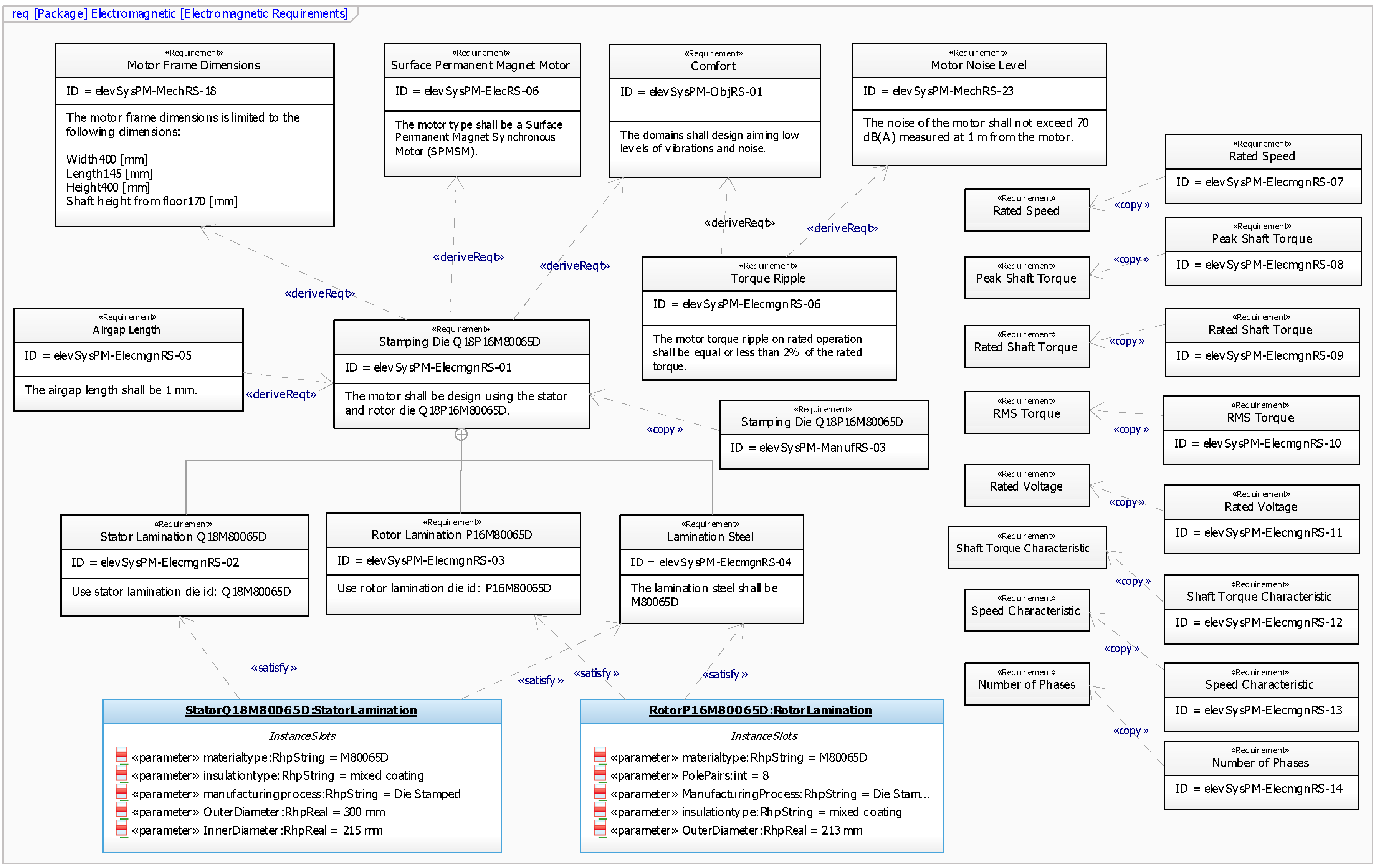
4.2. Deriving Requirements into Disciplines

The requirements are imported from Doors to Rhapsody to illustrate the process of derivation. In order to derive requirements into the different disciplines for this customized motor design, first, the operation characteristics curves (speed, torque, acceleration, jerk, and position) of the system must be obtained. A system assessment is carried out due to the initial specification not presenting these curves. The initial specification does present the important parameters to derive these curves. The equations that model the behavior of the system were obtained and agreed among the stakeholders and stored as constraint properties, as shown in Figure 10. These were processed through parametric diagrams to derive the curves shown in Figure 11.
The operating characteristics curves were obtained for a trip distance of 7.2 m, i.e., two floors of 3.6 m in height. The trip ends in 8 s, and at that distance, the brake is activated releasing the motor from doing work. The minimum time that is required by the elevator system to stop is 12 s, time for doors to open, people to get in/off, and doors to close. Therefore, the worst case scenario thermally speaking is to study a cycle of 20 s. All the aforementioned information is captured in the diagram to illustrate the derivation of mechanical requirements.
The requirement diagram in Figure 12 shows the relationships of this elevator operation characteristics requirement derived as a mechanical requirement from the initial requirements. Figure 13 shows the parametric diagrams that refine this requirement. Although not being shown in the figure, for each characteristic curve a mechanical requirement is also created, i.e., this requirement contains five mechanical requirements one for each curve. These are used later to derive the electromagnetic requirements.
Figure 14 shows some electrical requirements derivation relationships; it can be seen that some requirements may just be copied from the initial requirements. However, with a different id, to know to which specialized package it belongs. In summary, the converter is specified; due to its specifications, the motor shall be a three-phase motor with a current less than or equal to 15 A and the rated line-to-line voltage is limited to 400 V. The converter has the option of using space vector pulse-width modulation (PWM). Accordingly, a control requirement is derived stating to use this type of modulation because the operating voltage obtained from it is a maximum, thus lowering the operating current.
The motor selected for this particular case is a surface permanent magnet motor, selected due to the ease of manufacturing leading to lower costs and because the required speeds are considered that can be satisfied by this type of motor.

4.3. Deriving Electromagnetic Requirements

This phase is reached when the aforementioned requirements are considered to be good enough by both parts to start the design phase. However, the designer/manufacturer must derive more into specific-domains in order to detail better his objectives with the design. Following the framework, these requirements must be derived from the technical requirements of the different disciplines, not directly from the integrator’s requirement, if the need exists, first a copy should be made into a discipline before deriving into a domain-specific package. The same process backward if the creation of a new requirement needs to go to a higher level package.
Figure 15 shows an example of electromagnetic requirements derivation. In this case, the decision to use an already available design by selecting the stamping die for the stator and rotor laminations is taken based on the motor frame dimensions, type of motor, and cross-domain objective of comfort. This contains three requirements specifying the laminations for the stator, rotor, and type of steel. The stator and rotor laminations instances, also shown with its attributes in the diagram, satisfy these requirements. As a consequence of this requirement, the air gap is fixed to 1 mm. In addition, this requirement affects other domains; therefore, a copy is made to the manufacturing package. The torque ripple shall be less than 2% of the rated torque, because comfort is one of the main objectives and the requirement of the noise level. Finally, mechanical and electrical requirements, such as rated voltage, speed, torque, and others are copied.

5. Discussion

The specification stage is a critical part for the correct development of electric motors. The application of appropriate requirement engineering methods is compulsory to sufficiently carry out the process. This paper offers a requirement engineering framework from the perspective of the designer/manufacturer of electric motors. The framework puts special emphasis on the derivation of specialized requirements. The framework identifies the stakeholders, presented a classification of requirements, and shows the activities involved in requirement analysis to end with well-defined requirements in the context of motor development. This work attempts to provide a practical guideline to the small-medium industry of electric motors to cope with the specification stage.
The requirement engineering process involves good cooperative and communication skills among the stakeholders. Therefore, it is worth outlining that this framework lacks guidelines on this communication process. The paper only provides the developer proper contextual means to perform the process successfully. Nevertheless, the users of this framework may adjust it according to their needs.

Author Contributions

J.P. conceived the research. J.P. and C.A.R. designed the research, C.A.R. developed the framework and prepared the manuscript. G.U. and G.A. validated the work. All authors revised and approved the manuscript.

Funding

This research received no external funding.

Acknowledgments

This work has been partially supported by the program: “Red guipuzcoana de Ciencia, Tecnología e Innovación 2017” from Diputación Foral de Guipuzkoa.

Conflicts of Interest

The authors declare no conflict of interest.

References

  1. Bahill, A.T.; Henderson, S.J. Requirements Development, Verification, and Validation Exhibited in Famous Failures. Syst. Eng. 2005, 8, 1–14. [Google Scholar] [CrossRef]
  2. ABB. Low Voltage Motors Motor Guide; ABB: Zurich, Switzerland, 2018. [Google Scholar]
  3. WEG. Specification of Electric Motors; WEG: Jaraguá du Sol, Brazil, 2016. [Google Scholar]
  4. Jones, T. Motor Efficiency, Selection, and Management A Guidebook for Industrial Efficiency Programs; Consortium for Energy Efficiency: Boston, MA, USA, 2013. [Google Scholar]
  5. Chausovsky, A. Motor Market Update. In Proceedings of the Motor Summit, Zurich, Switzerland, 7–9 October 2014. [Google Scholar]
  6. Dick, J.; Hull, E.; Jackson, K. Requirements Engineering; Springer: Berlin, Germany, 2017; ISBN 978-3-319-61072-6. [Google Scholar]
  7. Arayici, Y.; Ahmed, V.; Aouad, G. A Requirements Engineering Framework for Integrated Systems Development for the Construction Industry. J. Inf. Technol. Constr. 2006, 11, 35–55. [Google Scholar]
  8. Rehman, S.; Gruhn, V. An Effective Security Requirements Engineering Framework for Cyber-Physical Systems. Technologies 2018, 6, 65. [Google Scholar] [CrossRef]
  9. Abo, R. Introduction to a Requirements Engineering Framework for Aeronautics. J. Softw. Eng. Appl. 2010, 3, 894–900. [Google Scholar] [CrossRef]
  10. Rivera, C.A.; Poza, J.; Ugalde, G.; Almandoz, G. A Knowledge Based System architecture to manage and automate the electrical machine design process. In Proceedings of the 2017 IEEE International Workshop of Electronics, Control, Measurement, Signals and Their Application to Mechatronics, ECMSM 2017, Donostia-San Sebastian, Spain, 24–26 May 2017. [Google Scholar]
  11. ABB Optimizer. Available online: http://www145.abb.com/selection (accessed on 14 November 2018).
  12. Kampker, A.; Kreisköther, K.; Büning, M.K.; Treichel, P.; Theelen, J. Automotive quality requirements and process capability in the production of electric motors. In Proceedings of the 2017 7th International Electric Drives Production Conference (EDPC), Würzburg, Germany, 5–6 December 2017. [Google Scholar]
  13. Dufrene, M. A methodological Framework to Support Integrated Ecodesign for Companies: Requirements and Conceptualization Towards a Software Platform. Ph.D. Thesis, University Grenoble Alpes, Saint-Martin-d’Hères, France, 2015. [Google Scholar]
  14. Jufer, M. Electric Drives: Design Methodology; Wiley-ISTE Press: London, UK, 2013; ISBN 9781848212176. [Google Scholar]
  15. Yilmaz, M. Limitations/capabilities of electric machine technologies and modeling approaches for electric motor design and analysis in plug-in electric vehicle applications. Renew. Sustain. Energy Rev. 2015, 52, 80–99. [Google Scholar] [CrossRef]
  16. Mccoy, G.A.; Douglass, J.G. Premium Efficiency Motor Selection and Application Guide—A Handbook for Industry; U.S. Department of Energy: Washington, DC, USA, 2014.
  17. Boteler, R.B.; Moore, M.E.; Turner, M.J. An evaluation and comparison of advanced motor technologies. In Proceedings of the 9th International Conference on Energy Efficiency in Motor Driven Systems, EEMODS 2015, Helsinki, Finland, 15–17 September 2015; pp. 412–423. [Google Scholar]
Figure 1. Generalization of the electric motor developer.
Applsci 08 02391 g001
Figure 2. Use case diagram of stakeholders in the specification context.
Applsci 08 02391 g002
Figure 3. Classification packages of requirements.
Applsci 08 02391 g003
Figure 4. Main activity diagram of the framework.
Applsci 08 02391 g004
Figure 5. Analyze the application requirements activity.
Applsci 08 02391 g005
Figure 6. Verify technical viability activity.
Applsci 08 02391 g006
Figure 7. Validate requirements and motor type activity.
Applsci 08 02391 g007
Figure 8. Generalized tests and verification of requirements.
Applsci 08 02391 g008
Figure 9. Initial requirements classification in Rational Doors.
Applsci 08 02391 g009
Figure 10. Equations modeling the elevator system operating characteristics.
Applsci 08 02391 g010
Figure 11. Operating characteristics curves of the elevator.
Applsci 08 02391 g011
Figure 12. Mechanical requirements derivation.
Applsci 08 02391 g012
Figure 13. Elevator operator characteristics refinement: (a) Parametric diagram to compute operating characteristics curves; and, (b) Requirement refinement through parametric diagrams.
Applsci 08 02391 g013
Figure 14. Electrical requirements derivation.
Applsci 08 02391 g014
Figure 15. Electromagnetic requirements derivation.
Applsci 08 02391 g015
Table 1. Examples of Requirements for each Package.
PackageRequirements Examples
Application Essential Requirements Package
OperabilityPower sources, ratings, torque, speed, efficiency, service factor, duty cycle, environmental conditions, insulation, mounting, frame size.
ServiceabilityRequirements related to ease of maintenance, ease of recycling, monitoring sensors (e.g., resistance temperature detectors (RTDs)).
ComfortNoise and Vibrations, dynamic smoothness control, continuous operation smoothness.
ReliabilityLife expectancy, permissible design or manufacturing tolerances, lead times, fault tolerances, tests.
SpecialTransportation, training, mounting, assembly (e.g., on site), commissioning.
Regulations/standards/policiesRegulations, standards or policies that the motor must accomplish or follow.
Technical Derived Requirements Package
MechanicalShaft torque, vibration and noise levels, types of bearings, rotor inertia, speed, shaft design, frame design, stresses, thermal constraints, cooling systems options, mounting constraints, enclosure type with the environment, insulation, size constraints, materials, sensors, related standards/regulations/policies, and others.
ElectricalElectromagnetic torque, winding arrangement, power factor, efficiency, voltage constraints, current constraints, size constraints, number of phases, insulation, thermal constraints, losses, torque density, electric motor type, materials, duty cycle or speed vs. torque curve, inductances, electromagnetic interferences, sensors, converter type, converter power ratings, related standards/regulations/policies, and others.
ControlControl strategy, switching frequency, converter type, sensors, phases, related standards/regulations/policies, and others.
ManufacturingMachined lamination, stamped lamination, coil formation, encapsulation, impregnation, interference fit, rotor balancing, winding process, magnets mounting, magnets retention, magnetization, winding process, machined shaft, forged shaft, stack assembly, tolerances, related standards/regulations/policies, and others.
Motor General or Specific ObjectivesCost, materials, efficiency, lead time manufacturing, lead time design, motor type, life cycle, and others not included in other requirements classification.
Table 2. Requirement Package IDs.
Requirement Package IDPackage Name
InRSIntegrator’s requirements
MechRSMechanical engineering requirements
ElecRSElectrical engineering requirements
ControlRSControl engineering requirements
ManufRSManufacturing engineering requirements
ObjRSSet objectives during the development process
ElecmgnRSElectromagnetic requirements

