Abstract
A trench-assisted multicore fiber (TA-MCF) with single-supermode transmission and nearly zero flattened dispersion is proposed herein. By adding a simplified microstructure cladding with only one ring of low-index inclusions on the basis of the multicore fiber, the microstructure cladding and mode-coupling mechanism were jointly employed into the TA-MCF to modulate light transmission. This guarantees that the TA-MCFs had sufficient capability for wideband dispersion management when only pure, germanium-doped, and fluorine-doped silica glass with low index differences were chosen to form the TA-MCF. Analyses also revealed that the TA-MCFs have the merits of shorter cut-off wavelength and flatter-top optical intensity distribution compared with traditional multicore fibers. After the investigation of the structural parameters’ influences on the dispersion of the fundamental supermode, two TA-MCFs with single-supermode transmission and nearly zero flattened dispersion were designed. For the seven-core TA-MCF, the dispersion varying from −0.46 to 1.35 ps/(nm·km) in the wavelength range of 1.50 to 2.04 μm, with bending loss as low as 0.085 dB/km and 35-mm bending radius at 1550 nm was achieved with index difference less than 0.015. The TA-MCFs proposed herein have the advantages of being a quasi-single material, with an all solid scheme and simplified structure.
1. Introduction
In recent years, transmission capacity achieved several terabit/s using dense wavelength-division multiplexing (DWDM) systems [1]. Group velocity dispersion (GVD), which deteriorates the performances of DWDM systems due to its temporal broadening effects on optical pulse, is one of the most important parameters of optical fibers. Fibers with wideband nearly zero flattened dispersion are more preferable in DWDM systems, because they can reduce the GVD-induced temporal broadening, as well as keep a uniform response among different channels [2,3,4].
To achieve wideband nearly zero dispersion, the waveguide dispersion Dw needs to be regulated to counterbalance the influences of the material dispersion Dm in the entire interested band, which is a difficult task for step index fibers (SIFs). With artificially periodic arranged air holes in the cladding, microstructure fibers (MSFs) possess more design flexibility compared with SIFs. By employing air holes with different sizes [5], or using elliptical instead of circular air holes [6], lots of flattened dispersion MSFs were proposed. Currently, MSFs are undoubtedly the most promising schemes in achieving wideband flattened dispersion fibers [5,6,7,8,9,10,11,12,13,14,15,16]. However, the design flexibility of MSFs also indicates the complexity of the fiber structure. It is difficult to keep tens or even hundreds of cladding air holes from deformation for dozens of kilometers during fiber drawing, while the collapse of air holes makes the dispersion of the MSF deviate from the original design. Furthermore, the fragility of the air–silica structure makes it a huge technical challenge to employ flattened dispersion MSFs for optical fiber communication systems that are hundreds of kilometers long.
Multicore fibers (MCFs) are another kind of fiber attracting lots of attention recently. According to coupled-mode theory (CMT), the guiding modes of MCFs are supermodes [17,18], which are formed due to the coupling of every individual core mode. In the formation of supermode, the propagation constant is also modulated, which further leads to a change in its dispersion. For example, by adjusting the coupling condition between the adjacent two cores, large negative dispersions as high as −4.5 × 10⁶ ps/(nm·km) were achieved at 1550 nm [19]. However, it is difficult to manage the dispersion of the MCFs in a broad band only using mode-coupling. Meanwhile, N-core MCFs commonly support at least N supermodes [20,21,22], and optical pulse broadening due to intermodal dispersion will severely deteriorate the performance of fiber-optic communication systems. Hence, the research on MCFs is mainly confined in the following four areas: low-cross-talk MCFs for space-division multiplexing (SDM) systems [23], large-mode-area MCFs for fiber lasers [24], MCF couplers [25], and MCF sensors [26]. To the best of our knowledge, there are still no reports regarding wideband nearly zero flattened dispersion MCFs with single-supermode transmission.
In this paper, a trench-assisted multicore fiber (TA-MCF) with wideband nearly zero flattened dispersion is proposed. We noticed that, in recent years, a new kind of multicore fiber, proposed and optimized for the use of space-division multiplexing (SDM), was also named TA-MCF. However, we must state that those fibers and the TA-MCFs proposed in our paper belong to two totally different purposes for distinct areas. For the TA-MCFs proposed for SDM, the main purpose of the trenches is to suppress the overlap of the electric field distribution and reduce the cross-talk between different cores. Thus, each fiber cell in the TA-MCFs is encircled by a low-index trench. However, our proposed TA-MCFs are intended to find application in high-speed DWDM systems. Hence, the main purpose of our paper was to present a novel fiber structure to boost the flexibility of GVD management by combining the merits of both MCFs and MSFs. To achieve this purpose, for the TA-MCF proposed herein, a multicore structure was used to take advantage of the mode-coupling mechanism in manipulating the light transmission. Meanwhile, only one ring of down-doped cylindrical inclusions was employed in the fiber cladding to form an all solid simplified microstructure cladding, which can also be seen as a low-index trench around the multicore region. It is shown that the dispersion of the fundamental supermode can be effectively managed with the help of this trench. In addition, a broader single-supermode operation region and a flatter-top optical intensity distribution were achieved through the introduction of the low-index trench. After the investigation of the structural parameters’ influences on the dispersion of the fundamental supermode, two kinds of TA-MCFs with single-supermode transmission and nearly zero flattened dispersion were designed. For the seven-core TA-MCF, flattened dispersion of −0.46 to 1.35 ps/(nm·km) was obtained from 1.50 to 2.04 μm, as well as bending loss as low as 0.085 dB/km at 1550 nm with 35-mm bending radius. More significantly, the flattened dispersion TA-MCFs proposed herein have all the advantages of a quasi-single material, with an all solid scheme and simplified structure.
2. Fundamental Theories
The diagrammatic sketch of a hexagonally arranged homogeneous six-core MCF is shown in Figure 1. Suppose that only a fundamental mode with a propagation constant of β is supported in each core at our interested wavelength. When the beam is launched into the fiber, the field distribution of a supermode can be considered as a superposition of each isolated mode under the 6 × 6 coupling matrix [27,28,29,30].
where κpq is the mode-coupling coefficient between the core p and q. For the six-core fiber given in Figure 1, κpq may take one of three different values, namely κ1, κ2, and κ3, based on the relative position of two cores(shown in Figure 1 and Equation (1)). By solving the eigenvalues of C, the effective mode indices neffi (i = 1, 2, 3, 4, 5, 6) of the six supermodes can be expressed as
where neff0 = β/k0 is the mode index of the individual step index fiber (SIF) cell. From Equation (2), we can see that the second and third supermodes, and the fourth and fifth supermodes are degenerated for a hexagonally arranged six-core MSF.
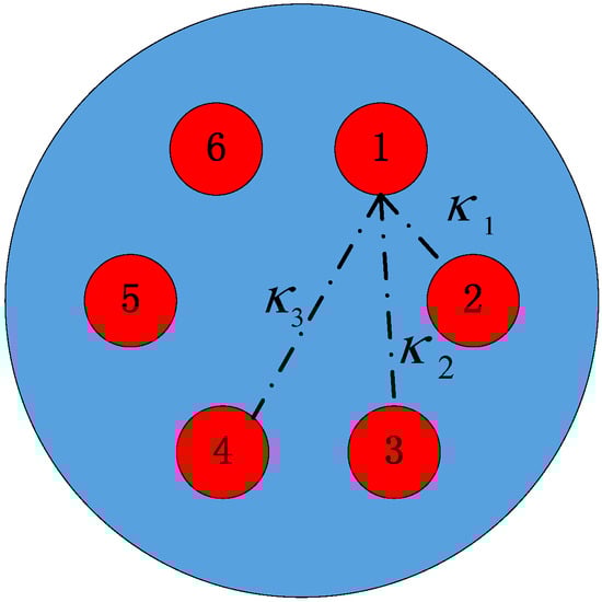
Figure 1.
The diagrammatic sketch of a hexagonally arranged homogeneous six-core multicore fiber (MCF).
The GVD is one of the most important parameters of optical fibers which limits the speed of each information channel. It can be treated as the sum of material dispersion and waveguide dispersion. The material dispersion can be derived from the Sellmeier equation of silica. Once the neff1 is solved, the waveguide dispersion Dw (λ) can be calculated by
where c is the speed of light in vacuum, λ represents the wavelength, and Re[neff1] is the real part of neff1.
In addition to GVD, the losses of the fiber are also crucial for an optical communication system. Confinement loss α can be obtained by
where Im[neff1] represents the imaginary part of neff1.
As for bending loss, its calculation can be summarized by the three steps. Firstly, the equivalent refractive index profile neq(x, y) of the bending fiber needs to be represented by the refractive index profile n(x, y) of the straight fiber using Equation (5) [31].
where x means that we assume the fiber is bending in the positive direction of the x-axis, and R is the bending radius. Secondly, the effective mode index of the bending fiber, which is denoted as neff1-bend, is obtained by numerically solving Maxwell equations under neq(x, y). Finally, the bending loss of the fiber can be computed using Equation (4), provided that the neff1-bend instead of neff1 is used in the calculation.
The performances of DWDM systems are deteriorated due to various nonlinear effects in optical fibers. From the nonlinear fiber optical theory, it is known that fibers with larger effective mode areas Aeff are less susceptible to nonlinear effects. Thus, the Aeff also needs to be considered during fiber design. According to its definition, Aeff can be expressed as
where Et represents transverse component of the electric field.
In addition to the value of Aeff, the two-dimensional distribution of optical intensity I of the mode field also plays an important role in nonlinear effect generation. Here, I is also known as the optical energy flux. It is the average of the instantaneous Poynting vector S over time and has a unit of W/m2. To better evaluate our proposed TA-MCF’s susceptibility to nonlinear effects, the detailed distribution of I was studied by a parameter called optical intensity ratio (IR). It is defined as
where I0 and I denote the optical intensity at the center of the MCF and in the six individual cores, respectively. Based on the definition of IR, we can conclude that the IR value approaching unity stands for a flatter mode field-intensity distribution for the six-core MCF. For a fiber with a flatter intensity profile, the optical power is distributed more uniformly in its cross-section. This further means a lower peak intensity under the same Aeff and input power, which is favorable for the prevention of nonlinear effects.
3. Structure and Modal Properties of the Six-Core TA-MCF
Figure 2 shows the diagrammatic sketch of the proposed six-core TA-MCF. The main conception of this fiber involves a simplified microstructure cladding with only one ring of low-index inclusions, added on the basis of the six-core MCF to combine the merits of both MSFs and MCFs. For ease of fabrication, pure, germanium-doped, and fluorine-doped silica glass, which are commonly used in the fabrication of step index fibers (SIFs), were chosen to form the TA-MCF. The matrix is pure silica glass with refractive index n0. The fiber core comprises six hexagonally arranged germanium up-doped high-index silica inclusions (red-colored circles) with refractive index n1 and diameter d1. Outside the fiber cores, there is a hexagonal low-index trench which is composed of twelve fluorine down-doped silica inclusions with refractive index n2 and diameter d2 (gray-colored circles). Every three neighboring inclusions are arranged in regular triangles with inclusion-to-inclusion space denoted as Λ.
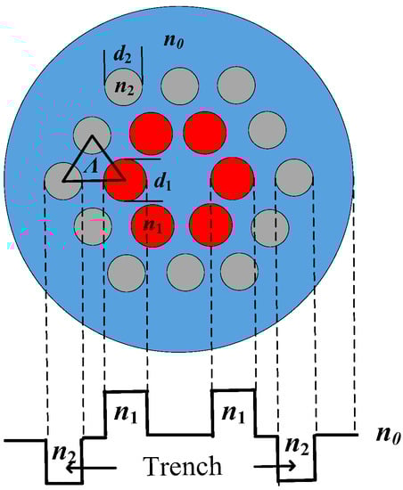
Figure 2.
Diagrammatic sketch of the six-core trench-assisted MCF (TA-MCF) and its equivalent refractive index profile.
To investigate the low-index trench’s influences on the modal properties of the six-core MCF, structural parameters with n0 = 1.45, n1 − n0 = 0.015, n2 − n0 = −0.015, Λ = 2.2 μm, d1/Λ = 0.80, and d2/Λ = 0.60 were initially chosen. Figure 3 shows the mode indices of the fundamental and second-order supermodes for the six-core MCF with and without trench. It can be seen that the effective indices were reduced if the low-index trench was added for both the fundamental and second-order modes. From Equation (2) and Figure 3, we can conclude that the effective index nfund of the fundamental supermode is always larger than neff0 of the SIF. This indicates that this supermode is always supported by the six-core MCF regardless of the trench. As for the index of the degenerate second-order mode nsec, whether its value is larger than neff0 or not depends on the sign of κ1-κ2-κ3. For the six-core MCF without the trench, its nsec values became smaller than neff0 after 1205 nm. This crossing wavelength had a 219-nm blue shift to 986 nm after the trench was added. More importantly, the two nsec curves intersected with the refractive index curve of pure silica at 1298 and 1198 nm. This means that the second-order mode is cut off after those wavelengths, and the introduction of the low-index trench results in a blue shift of the cut-off wavelength and a broader single-mode regime. The electric-field distributions of the second-order mode of TA-MCF at 1.1 μm and 1.2 μm are shown in Figure 3b,c. As can be seen from Figure 3b, the light is mainly confined in the core region before the cut-off wavelength. After that wavelength, it is clearly seen that light is coupled out of the cores (Figure 3c).
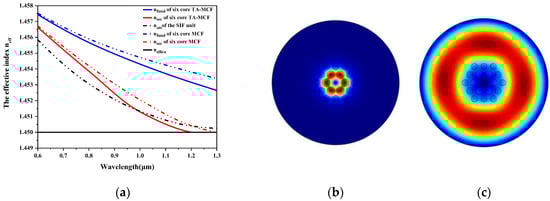
Figure 3.
(a) The effective indices of the step index fiber (SIF) unit, fundamental supermode, and second-order supermode of the six-core TA-MCF and the six-core MCF; the electric field distributions of the second-order supermode of the TA-MCF at (b) 1.1 μm, and (c) 1.2 μm.
Figure 4 shows the total dispersion of the SIF unit, the six-core MCF, and the TA-MCF as a function of wavelength. Upon comparing the dispersion curve of the six-core MCF to that of SIF, it can be seen that mode-coupling imposes huge influences on light transmission. By further adding a trench in the MCF, the dispersion value is obviously altered and the dispersion curve becomes flatter at the communication band. This indicates that the TA-MCF proposed herein is promising for achieving wideband flattened dispersion.
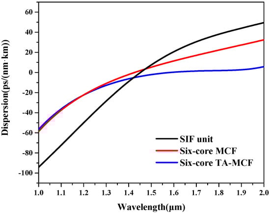
Figure 4.
The total dispersions of the SIF unit, six-core MCF, and TA-MCF as a function of wavelength.
The optical intensity distribution of the fundamental supermodes was investigated in Figure 5 for MCFs with and without the trench. From Figure 5a,f, we can see that the light is well confined in the six-core MCF at short wavelengths and gradually approaches a flatter-top distribution as the wavelength becomes longer for both fibers. This trend can be also predicted by Figure 5g, in which the IR values of the two fibers monotonically increased with the increment of wavelength. Also seen from Figure 5g, it was found that the IR value of the TA-MCF was always larger than that of the six-core MCF in the whole range of 1.0–2.0 μm. According to the definition of IR, this means that the introduction of the low-index trench leads to a more uniform distribution of light field. After adding the trench, the IR value reached as high as 0.98 at 1550 nm.
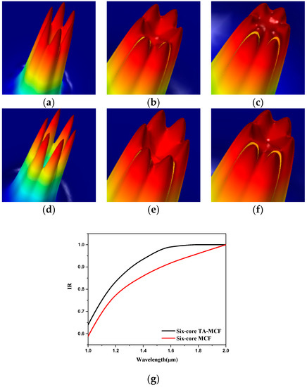
Figure 5.
The optical intensity distribution of the fundamental supermode of (a–c) the six-core TA-MCF, and (d–f) the six-core MCF at 1.0 μm, 1.55 μm, and 2.0 μm, respectively; (g) the intensity ratio (IR) value of the six-core TA-MCF and six-core MCF.
From the analyses above, we can conclude that the TA-MCF proposed herein shows a superior all solid scheme and simplified structure compared to the air–silica MSF. At the same time, it also has the advantage of a more effective dispersion management, broader single-supermode operation region, and flatter-top optical intensity distribution compared with the MCF.
4. Structural Parameter Influence on the Dispersion
To obtain the six-core TA-MCF with wideband nearly zero flattened dispersion, the structural parameter influence on the dispersion of the fundamental supermode were studied, as shown in in Figure 6. The TA-MCF with n0 = 1.45, n1 = 1.465, n2 = 1.435, Λ = 2.2 μm, d1/Λ = 0.80. and d2/Λ = 0.60, which is the same as that described in Section 3, was initial chosen. To avoid unrealistic doping concentrations, the index differences between the germanium up-doped inclusions and the pure silica matrix were limited to no greater than 0.017, and the index differences between the fluorine down-doped inclusions and the pure silica matrix were set to no less than −0.016. In Figure 6a,b, the germanium up-doped inclusions’ impacts on the dispersion were investigated by changing n1 and d1/Λ, respectively. From the analysis of Section 3, we know that the fundamental supermode has a flat-topped field distributed over the entire core in the communication bands, and that the core region can be treated as a whole when analyzing the relationship between its dispersion and structural parameters. Because larger n1 and d1/Λ means a larger average index of the fiber core, from Figure 6a,b, we can conclude that the dispersion value increased monotonously with the increment of wavelength in the range of 1.4 to 2.0 μm if the equivalent core index is large. However, this monotonicity is not favorable in the respect of flattened dispersion TA-MCF designing. With the decrement of n1 and reduction of d1/Λ, the equivalent index of the fiber core was reduced and the monotonicity of dispersion curve could be broken. A dispersion curve with a local maximum at short wavelength and a local minimum at long wavelength was obtained. Meanwhile, almost the entire dispersion curve dropped as a whole with the decrement of core index. Next, the low-index trench’s influences on the dispersion of the fundamental supermode were investigated in Figure 6c,d. Because the trench was composed of twelve fluorine down-doped inclusions, the decrement of n2 and enlargement of d2/Λ both led to the reduction of average index in the trench region. As can be seen from Figure 6c,d, it was found that the relationship between trench index and dispersion was analogous to the relationship between core index and dispersion shown in Figure 6a,b. A trench with high index meant a monotonously increasing dispersion curve, while the monotonicity was lost and the entire dispersion curve dropped by decreasing the trench index. At last, the inclusion-to-inclusion space Λ was changed from 2.0 to 2.3 μm at a step of 0.1 μm in Figure 6e. The numerical results revealed that, with the enlargement of Λ, the dispersion curves rose as a whole and the flatness of the dispersion curves was weakly changed.
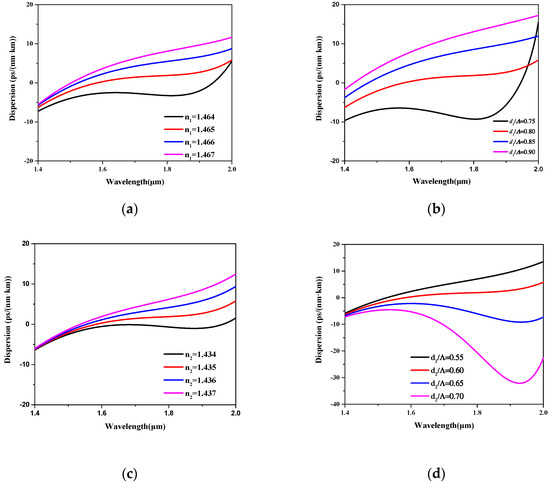
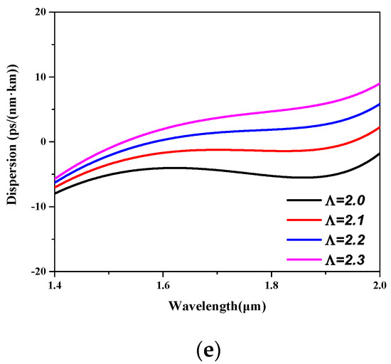
Figure 6.
The influences of structural parameters on the dispersion (a) n1 from 1.464 to 1.467; (b) d1/Λ from 0.75 to 0.90; (c) n2 from 1.434 to 1.437; (d) d2/Λ from 0.55 to 0.7; (e) Λ from 2.0 to 2.3 μm.
Taking all the effects mentioned above into consideration, conclusions can be drawn that the low index difference between the core and matrix and the high index difference between the matrix and trench are essential to break the monotonicity and further manage the slope of the dispersion curve. Meanwhile, the amplitude of the curve can be adjusted by tuning the inclusion-to-inclusion space Λ when designing the flattened dispersion TA-MCF.
5. Design of Flattened Dispersion TA-MCFs with Low Bending Loss
Based on the analyses given above, a nearly zero dispersion flattened six-core TA-MCF was designed with Λ = 2.195 μm, d1/Λ = 0.822, n1 = 1.4648, d2/Λ = 0.628, and n2 = 1.4346. Using these parameters, the calculated cut-off wavelength was 1197 nm, and single-mode operation could be guaranteed after that wavelength. Figure 7a shows that the flattened dispersion of the fundamental supermode varied from −1.03 to 0.75 ps/(nm·km) in the wavelength range of 1.52 to 2.01 μm, which completely covers the C(1530–1565 nm) + L(1565–1625 nm) + U(1625–1675 nm)communication band. In Figure 7b, the optical intensity distribution IR and effective mode area Aeff were investigated as a function of wavelength. The numerical results showed that IR reached 0.92 and Aeff was 48.41 μm2 at 1550 nm. The effective mode area of the TA-MCF proposed herein is larger than most air–silica flattened dispersion MSFs reported. Furthermore, compared to Gaussian distribution, the flat-topped distribution is less susceptible to nonlinear effects.
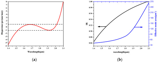
Figure 7.
(a) The nearly zero flattened dispersion, and (b) the IR value (left axis) and the effective mode area (right axis) of the designed six-core TA-MCF as a function of wavelength.
Loss is another important parameter for optical fibers. For the six-core TA-MCF, the numerical simulated confinement loss was as low as 3 × 10⁻⁷ dB/km at 1550 nm. A weakly guiding fiber is more susceptible to bending. In Figure 8, the bending losses were calculated with different bending radii at 1550 nm. For comparison, the low0index trench was removed and the bending loss of the six-core MCF without the trench was also calculated and presented in Figure 8. From Figure 8, we can see that the introduction of the low-index trench deteriorated the bending loss. This can be explained by the introduction of trench leading to the reduction of the mode effective index stated in Section 3, which inevitably makes the TA-MCF more sensitive to bending. Moreover, for the six-core fiber, the refractive index of the central region was equal to that of the matrix, and this type of equivalent refractive index profile makes the fiber more sensitive to bending. However, the numerical results showed that the bending loss of our proposed TA-MCF was still less than 4.9 × 10⁻⁴ and 0.1 dB/km at 55- and 45-mm bending radius, which is sufficiently low for practical applications.
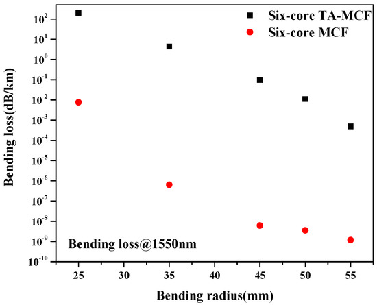
Figure 8.
Bending losses of the six-core TA-MCF and six-core MCF at 1550 nm with different bending radii.
To further reduce the bending loss, an extra germanium up-doped rod with a refractive index n3 and diameter d3 was added in the fiber center to fill the central index valley, and a seven-core TA-MCF was proposed in Figure 9. After parameter optimization, flattened dispersion fluctuating from −0.46 to 1.35 ps/(nm·km) in the wavelength range 1.50 to 2.04 μm was obtained under the parameters of Λ = 2.1 μm, d1/Λ = 0.853, n1 = 1.4648, d2/Λ = 0.657, n2 = 1.4351, d3/Λ = 0.657, and n3 = 1.4545, as shown in Figure 10. In Figure 11, the bending loss of the seven-core TA-MCF was studied. The bending losses of the seven-core MCF without trench and the bending loss of the six-core TA-MCF by removing the central germanium-doped rod are also presented in Figure 11 for ease of comparison. From Figure 11, conclusions can be drawn that the MCF without the trench always has the lowest bending loss of the three. However, the bending loss can be reduced greatly by adding a germanium up-doped rod in the center of the fiber. For the six-core TA-MCF proposed herein, the bending loss was reduced from 2.95 dB/km for the six-core TA-MCF to less than 0.085dB/km at 1550 nm with 35-mm bending radius.
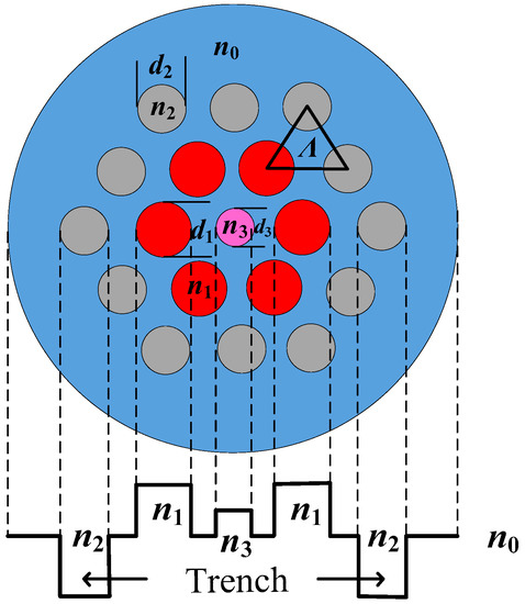
Figure 9.
Cross-section of the seven-core TA-MCF and its equivalent refractive index profile.
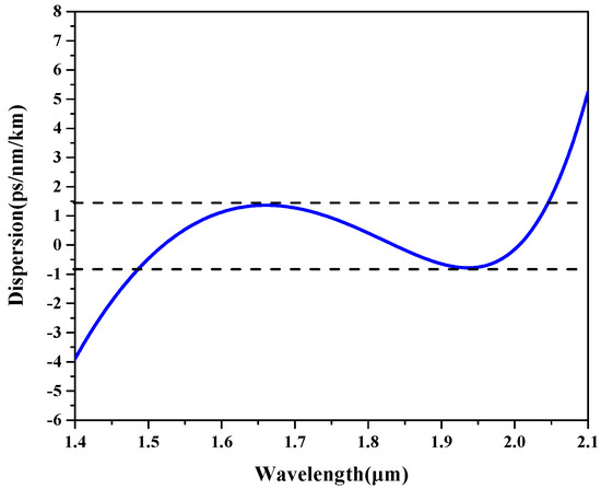
Figure 10.
The nearly zero flattened dispersion of the seven-core TA-MCF as a function of wavelength.
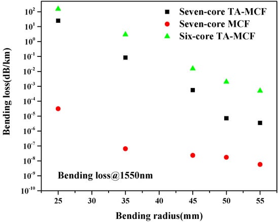
Figure 11.
Bending losses of the seven-core TA-MCF, seven-core MCF without trench, and six-core TA-MCF by removing the central rod at 1550 nm with different bending radii.
Due to their high degrees of freedom in structure design, MSFs are undoubtedly currently one of the most promising schemes in achieving wideband nearly zero flattened dispersion fibers. Many flattened dispersion MSFs were proposed. MSFs usually refer to fibers containing microstructures in their cross-section. From this perspective, the TA-MCFs proposed in this paper can also be regarded as MSFs. Below, we summarize and list some results of the reported flattened dispersion MSFs to make a comparison with our proposed fiber [8,9,10,11,12,13,14,15,16].
From Table 1, it can be seen that the two fibers proposed in this paper have the simplest structures of all, with only 18 or 19 inclusions to form the microstructure. Meanwhile, all solid schemes instead of commonly used air–silica structures were employed in our design. By doing this, the disadvantages due to the introduction of air holes, such as to keep tens or even hundreds of cladding air holes from deformation for dozens of kilometers during fiber drawing, can be avoided. Furthermore, all the materials used in our design are pure, germanium-doped, and fluorine-doped silica glass with index differences less than 0.016. These glasses are commonly used in SIF fabrication and have perfectly matched physical characteristics of transition temperature, coefficient of thermal expansion, coefficient of viscosity, etc. Compared with all solid MSFs formed by two or more glasses of high index difference [12,13], our design greatly reduces the difficulties in glasses pairing and fiber fabrication.

Table 1.
Comparison between the proposed flattened dispersion trench-assisted multicore fibers (TA-MCFs) in this paper with other studies.
Another obvious advantage of our design over other flattened dispersion MSFs is that the TA-MCFs proposed herein have relatively larger Aeff. This is because conventional single-core MSFs use the microstructured cladding to manage their dispersion. This means that a small core is necessary for the light fully interacting with the microstructured cladding, which further results in a small Aeff. On the other hand, for our TA-MCFs, a mode-coupling mechanism was introduced using a multi-core structure to enhance the ability of transmission control. Together with the low-index trench, a wideband flattened dispersion can be achieved with a larger core. We believe the TA-MCFs proposed herein can find applications in high-speed DWDM systems.
6. Conclusions
In conclusion, a TA-MCF was proposed by combining the advantages of MCFs and MSFs. Compared with MSF, the TA-MCF proposed herein shows superiorities of an all solid scheme and simplified structure. Meanwhile, numerical simulations showed that it also has the merits of a more effective dispersion management, a broader single-supermode operation region, and a flatter-top optical optical intensity distribution compared with MCFs. Though optimization of structure parameters, a flattened dispersion six-core TA-MCF with dispersion from −1.03 to 0.75 ps/(nm·km) in the wavelength range 1.52 to 2.01 μm, cut-off wavelength of 1197 nm, intensity ratio of 0.92, effective mode aera of 48.41 μm2, and bending loss less than 0.1 dB/km with bend radius larger than 45 mm at 1550 nm was obtained. To further reduce the bending loss, an extra updoped inclusion was added in the fiber center and a seven-core TA-MCF was presented. The numerical results showed that dispersion varying from −0.46 to 1.35 ps/(nm·km) in the wavelength range 1.50 to 2.04 μm and bending loss as low as 0.085 dB/km with 35-mm bending radius at 1550 nm was achieved with index differences as low as 0.015 between the matrix and inclusions. The TA-MCFs proposed herein have all the advantages of wideband nearly zero flattened dispersion, single-mode operation, flat-top field distribution, qusi-single material, all solid scheme, and simplified structure, and can be used in long-distance optical fiber communication systems.
Author Contributions
W.W. and S.Q. conceived and wrote the manuscript, and all authors contributed to the completion of the manuscript.
Funding
This research received no external funding.
Acknowledgments
This work was supported by the Open Subject of Jiangsu Key Laboratory of Meteorological Observation and Information Processing (KDXS1107) and College Science Research Program of Hebei Province (BJ2017108), and the Natural Science Foundation of Hebei Province (F2018105036), National Natural Science Foundation of China (61735011), and Natural Science Foundation of Hebei Province (F2016203389, 2015003053).
Conflicts of Interest
The authors declare no conflict of interest.
References
- Goel, A.; Pandey, G. Design of broadband dispersion flattened fiber for DWDM system: Performance analysis using various modulation formats. Opt. Fiber Technol. 2018, 42, 109–118. [Google Scholar] [CrossRef]
- Matsui, T.; Zhou, J.; Nakajima, K.; Sankawa, I. Dispersion-flattened photonic crystal fiber with large effective area and low confinement loss. J. Lightwave Technol. 2006, 23, 4178–4183. [Google Scholar] [CrossRef]
- Liu, X.; Han, L.H.; Jia, X.Y.; Wang, J.L.; Yu, F.Y.; Yu, Z.Y. Design of hybrid-core PCF with nearly-zero flattened dispersion and high nonlinearity. Chin. Opt. Lett. 2015, 13, 17–21. [Google Scholar] [CrossRef]
- Maji, P.S.; Chaudhuri, P.R. Gain and bandwidth investigation in a near-zero ultra-flat dispersion PCF for optical parametric amplification around the communication wavelength. Appl. Opt. 2015, 54, 2363–3272. [Google Scholar] [CrossRef]
- Wang, W.; Hou, L.T.; Song, J.J.; Zhou, G.Y. Design of double cladding dispersion flattened photonic crystal fiber with deformation insensitive outer cladding air-holes. Opt. Commun. 2009, 282, 3468–3472. [Google Scholar] [CrossRef]
- Yin, A.H.; Xiong, L. Characteristics analysis of extruded elliptical hole photonic crystal fibers with square air-core. Optik 2014, 125, 4069–4071. [Google Scholar] [CrossRef]
- Wang, W.; Hou, L.T.; Liu, Z.L.; Zhou, G.Y. Validity condition of separating dispersion of PCFs into material dispersion and geometrical dispersion. Chin. Opt. Lett. 2009, 7, 768–770. [Google Scholar] [CrossRef]
- Kunimasa, S.; Koshiba, M. Chromatic dispersion control in photonic crystal fibers: Application to ultra-flattened dispersion. Opt. Express 2003, 11, 843–852. [Google Scholar] [CrossRef]
- Wu, T.L.; Chao, C.H. A novel ultraflattened dispersion photonic crystal fiber. IEEE Photonic Technol. Lett. 2004, 17, 67–69. [Google Scholar] [CrossRef]
- Kaijage, S.F.; Namihira, Y.; Hai, N.H.; Begum, F.; Razzak, S.M.A.; Kinjo, T.; HIGA, H.; Zou, N.Y. Multiple defect-core hexagonal photonic crystal fiber with flattened dispersion and polarization maintaining properties. Opt. Rev. 2008, 15, 31–37. [Google Scholar] [CrossRef]
- Wang, D.; Wang, L.L. Design of topas microstructured fiber with ultra-flattened chromatic dispersion and high birefringence. Opt. Commun. 2011, 284, 5568–5571. [Google Scholar] [CrossRef]
- Martynkien, T.; Pysz, D.; Ryszard, S.; Ryszard, B. All-solid microstructured fiber with flat normal chromatic dispersion. Opt. Lett. 2014, 39, 2342–2345. [Google Scholar] [CrossRef] [PubMed]
- Klimczak, M.; Siwicki, B.; Skibiński, P.; Pysz, D.; Stepień, R.; Heidt, A.; Radzewicz, C.; Buczyński, R. Coherent supercontinuum generation up to 23 µm in all-solid soft-glass photonic crystal fibers with flat all-normal dispersion. Opt. Express 2014, 22, 18824–18832. [Google Scholar] [CrossRef] [PubMed]
- Su, W.; Lou, S.Q.; Zou, H.; Han, B.L. A highly nonlinear photonic quasi-crystal fiber with low confinement loss and flattened dispersion. Opt. Fiber Technol. 2014, 20, 473–477. [Google Scholar] [CrossRef]
- Hsu, J.M. Tailoring of nearly zero flattened dispersion photonic crystal fibers. Opt. Commun. 2016, 316, 104–109. [Google Scholar] [CrossRef]
- Lu, D.K.; Li, X.H.; Zeng, G.H.; Liu, J. Dispersion Engineering in Single-Polarization Single-Mode Photonic Crystal Fibers for a Nearly Zero Flattened Profile. IEEE Photonics J. 2017, 9, 1–8. [Google Scholar] [CrossRef]
- Szostkiewicz, L.; Napierala, M.; Ziolowicz, A.; Pytel, A.; Tenderenda, T.; Nasilowski, T. Cross talk analysis in multicore optical fibers by supermode theory. Opt. Lett. 2016, 41, 3759–3762. [Google Scholar] [CrossRef] [PubMed]
- Yi, C.S.; Zhang, P.Q.; Dai, S.X.; Wang, X.S.; Wu, Y.H.; Xu, T.F.; Nie, Q.H. Multicore chalcogenide photonic crystal fibers for large mode area and mode shaping. Opt. Commun. 2013, 311, 270–274. [Google Scholar] [CrossRef]
- Wei, W.; Zhang, X.Y.; Huang, Q.; Ren, X.M. Analysis of dispersions of coupled asymmetric subwavelength-diameter wires. Optik 2014, 125, 2749–2751. [Google Scholar] [CrossRef]
- Xia, C.; Bai, N.; Ozdur, I.; Zhou, X.; Li, G.F. Supermodes for optical transmission. Opt. Express 2011, 19, 16653–16664. [Google Scholar] [CrossRef]
- Zhou, C.; Zhang, H.K.; Song, P.; Wang, J.; Li, X. Design and optimization of a multi-cores photonic crystal fiber for spatial flat in-phase supermode laser output. Opt. Fiber Technol. 2015, 21, 160–163. [Google Scholar] [CrossRef]
- Jollivet, C.; Mafi, A.; Flamm, D.; Duparré, M.; Schuster, K.; Grimm, S.; Schülzgen, A. Mode-resolved gain analysis and lasing in multi-supermode multi-core fiber laser. Opt. Express 2014, 22, 30377–30386. [Google Scholar] [CrossRef] [PubMed]
- Richardson, D.J.; Fini, J.M.; Nelson, L.E. Space-division multiplexing in optical fibres. Nat. Photonics 2013, 7, 354–362. [Google Scholar] [CrossRef]
- Xiang, S.; Hu, X.W.; Yang, L.Y.; Dai, N.L.; Wu, J.J.; Zhang, F.F.; Peng, J.G.; Li, H.Q.; Li, J.Y. Helical long-period grating manufactured with a CO2 laser on multicore fiber. Opt. Express 2017, 25, 10405–10412. [Google Scholar] [CrossRef] [PubMed]
- Li, X.; Sun, B.; Yu, Y. Ultra-wide bandwidth wavelength selective couplers based on the all solid multi-core Ge-doped fibre. Opto-Electron. Rev. 2014, 22, 166–170. [Google Scholar] [CrossRef]
- Fernandes, L.A.; Grenier, J.R.; Aitchison, J.S.; Herman, P.R. Fiber optic stress-independent helical torsion sensor. Opt. Lett. 2015, 40, 657–660. [Google Scholar] [CrossRef] [PubMed]
- Xia, C.; Eftekhar, M.A.; Correa, R.A.; Antonio-Lopez, J.E.; Schülzgen, A.; Christodoulides, D.; Li, G.F. Supermodes in Coupled Multi-Core Waveguide Structures. IEEE J. Sel. Top. Quant. 2016, 22, 196–207. [Google Scholar] [CrossRef]
- Jin, W.X.; Jian, S.S. Numerical and simulation analyses on supermode characteristics of dual-core fiber and four-core fiber. Optik 2017, 132, 32–38. [Google Scholar] [CrossRef]
- Ren, W.H.; Tan, Z.W. A study on the coupling coefficients for multi-core fibers. Optik 2016, 127, 3248–3252. [Google Scholar] [CrossRef]
- Zheng, S.W.; Ren, G.B.; Lin, Z.; Jian, S.S. Mode-coupling analysis and trench design for large-mode-area low-cross-talk multicore fiber. Appl. Opt. 2013, 52, 4541–4548. [Google Scholar] [CrossRef]
- Wang, Z.Q.; Ye, J.J.; Zhao, C.L.; Zhang, Z.X.; Wang, J.F.; Zhang, S.Q.; Jin, S.Z. Design of large-mode-area single-mode optical fiber with lowing bending loss for Raman distributed temperature sensor. Opt. Fiber Technol. 2013, 19, 671–676. [Google Scholar] [CrossRef]


© 2018 by the authors. Licensee MDPI, Basel, Switzerland. This article is an open access article distributed under the terms and conditions of the Creative Commons Attribution (CC BY) license (http://creativecommons.org/licenses/by/4.0/).