1. Introduction
The energy that is needed for highly efficient transfer has shown a continuous growth, as the energy reduction. For highly efficient power convection, gas turbine is an important device at present. In order to enhance power transform efficiency, an available approach always been applied is increasing the inlet temperature in the gas turbine [
1]. The research indicates that the ability of power conversion on the turbine can be improved by 10% as the inlet temperature increasing 55 K. However, higher gas temperature will lead to larger thermal loads on the thermal surface in the transition piece, and will even threaten the working lifespan and the reliability of gas turbine hot component [
2]. Therefore, the cooling technology on such a high temperature components becomes to be a critical task.
The transition piece, which is an important component combining the combustor and turbine, is studied by scholars for heat protection. A. Gallegos Muñoz [
3] investigated the geometric construction of transition piece effected on the contours of temperature and velocity in the outlet section, by using CFD. Then, structural optimization was carried out by the Genetic Algorithms (GA). The optimized results indicated that the average inlet gas temperature and the average velocity were decreased by 2.32% and about 7.73%, respectively.
Wang et al. [
4,
5] provided the sheath with hundreds of small impingement cooling jets can enhance the convective heat transfer coefficient by the strong forced convention coolant, which was installed over the external thermal surface of the transition piece. Both experimental and computational studies were carried out. A 1/7th section of a circle was designed to simulate a part of the dump diffuser accommodating one and two half transition pieces. The experimental results showed that the non-sheathed case provided a 40% reduction in pressure losses when comparing with the sheathed case, but 35% increase in the maximum surface temperature difference and an increase of 13–22% in other surface temperature difference, based on the temperature difference of the bulk inlet and outlet temperature. The CFD results also identified that the addition of the sheath was advised.
Xu [
6] considered the coolant hole’s angle and the injection angle of coolant flow effected on the heat transfer efficiency of impinging. The CFD simulation models were employed and the results indicated that heat transfer effectiveness was improved with the rising hole’s inclination and injection angle, since the thermal surface was impinged by more coolant directly. They [
7], also investigated that jet flow with water drop promoted impinging cooling efficiency increasing. They concluded the mass of 3 × 10
−3 kg/s droplets with diameters of 5–35 μm could enhance the 90% cooling effectiveness and reduce 122 K of surface temperature. For enhancing the impinging cooling efficiency, they [
8] designed pin fins in the coolant chamber to increase the turbulence, and optimized the pin fin diameter and the distance. After the pin fins were brought in, the numerical reports showed that the temperature declined of 38.77 K, when comparing to without pin fins. With the mist injecting into the cooling chamber, the area weighted average temperature got a lower value without excess pressure loss.
The transition piece in the above literature has a smooth thermal surface. However, non-smooth thermal surfaces may have higher cooling efficiency or better convective heat transfer enhancement. How to design a surface with excellent thermal protection ability remains a challenge for researchers. After billions of years of evolution, some biological structures already have excellent properties, which could provide inspiration for thermal surface designers.
Nowadays, the excellent structure of creatures in natural evolution has provided a lot of inspiration for engineering. The analysis shows that the non-smooth structural characteristics of the livings’ surface morphology can change the flow. Cui et al. [
9] considered four types of bionic surfaces of reducing pressure loss, which were riblet-shaped, ridge-shaped, V-shaped, and placoid-shaped, respectively. Using the Lattice Boltzmann Method (LBM), an order for drag reduction coefficient (
) was generated, as follows:
>
>
>
. The results suggested that the ridge-shaped structure effected on reducing significantly, and the riblet-shaped structure could strengthen turbulence flow.
Hu et al. [
10] explored the heat transfer performance of coolant stream coming out for the hollow shell, which was designed by using the bionic Barchan-dune shaped (BDS) concept. They claimed that the BDS design could make the coolant stream attach to the test surface more firmly, but with more friction loss.
Referring to turbulence flow characteristic of creatures’ structure, the thermal protection of the transition piece may be solved more efficiently. In this paper, inspired by alopias’ gill arch, a two-chamber rectangular model with rib turbulence is designed for enhancing heat transfer efficiency. Because the study of the biomimetic thermal surface is in comparison to parameter differences, the numerical simulations that have turned out to be more available and less expensive than the contrast experiments are carried out. The CFD method is applied to investigate the flow behavior and the heat transfer of the coolant flowing in cooling chamber with rib surface.
2. Bionic Design
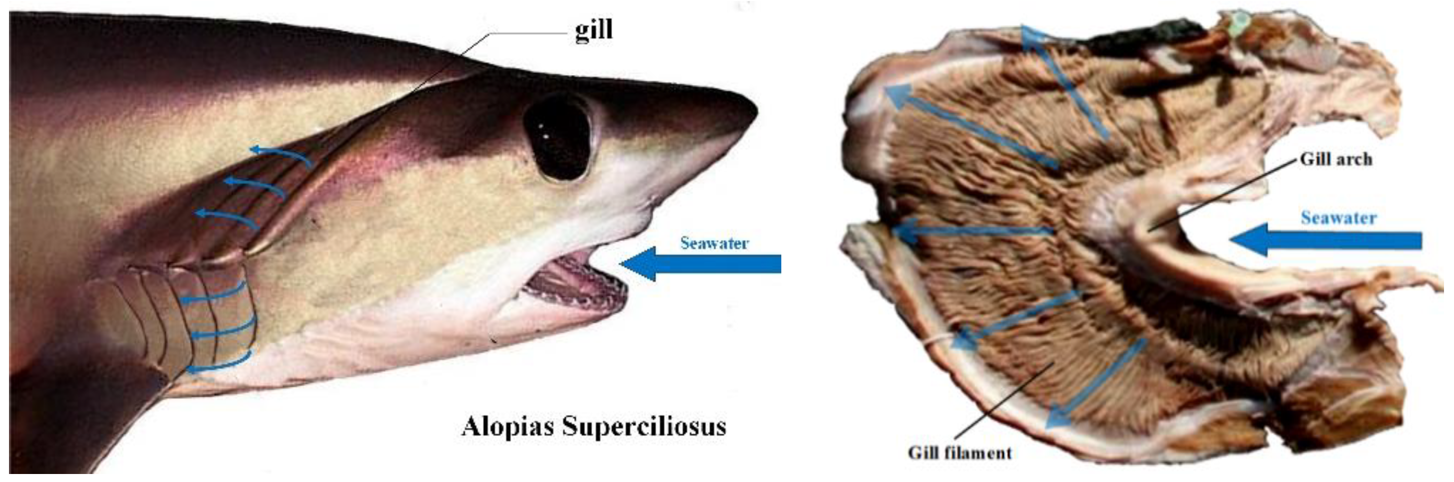
To adapt to the marine environment, alopias need to complete respiration by absorbing the scarce oxygen in the deep water, and the excellent morphology of its gills can help oxygen exchange efficiently. The gill morphological structures of alopias supercilious is shown in the
Figure 1. The branchial arch of alopias changes the flow directing of the seawater from mouth to gill filament, meanwhile more turbulence is generated. The oxygen in the flow can be contacted with the capillaries in gill filaments easily [
11]. The formation of turbulence that is inspired by the gill arches can strengthen the absorption of the oxygen; it is likely that more turbulence may improve the convective heat transfer of the coolant. In order to seek the correctness of this idea, the thermal surface with ribbed turbulators will be designed in a simplified gas turbine transition piece.
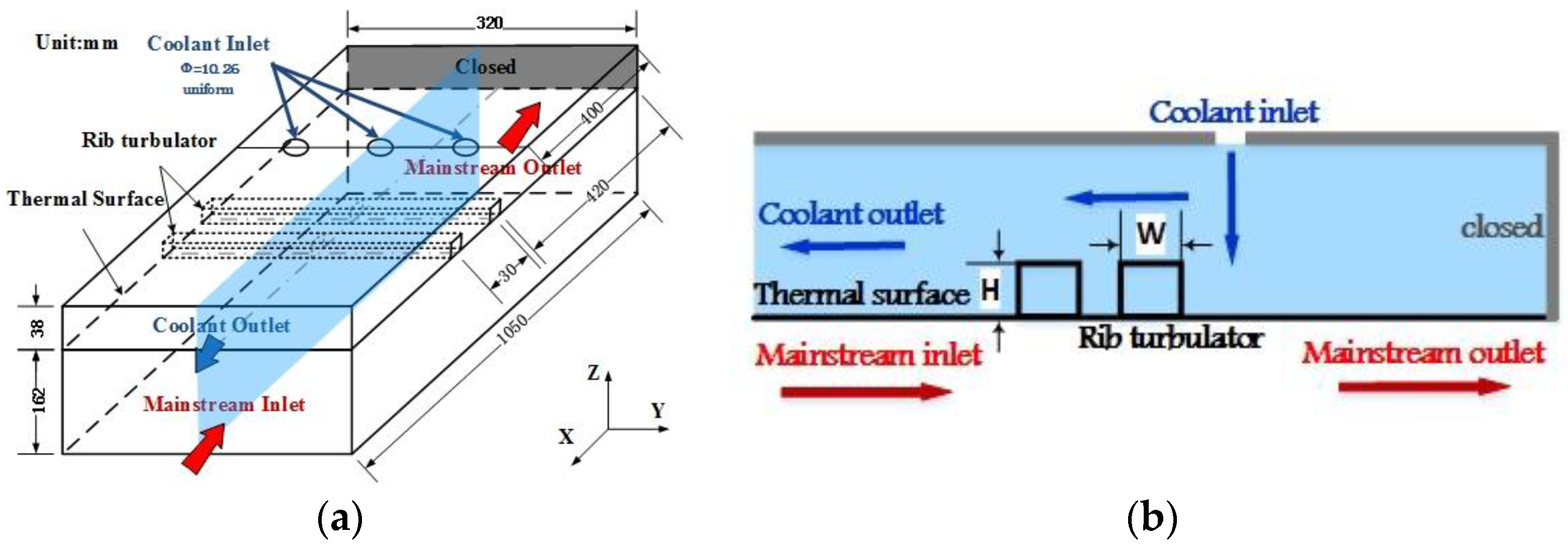
Since the structure of gas turbine transition piece in operating is complex, the double-chamber simplified model is designed in this paper. In order to exclude the effect of curvature on the heat transfer, the simplified model is rectangular, as in
Figure 2a. The “X” direction is the coolant streamwise, and the direction of the gas flow is countercurrent. The flowing length
L = 1050 mm and the width
W = 320 mm are used. In the figure, both sides of the below channel in the X axis direction are non-sealed, which is the mainstream chamber. Contrarily, one side of the above channel as the coolant chamber is opened, and the other side is closed. The height of coolant chamber and gas chamber are 38 mm and 162 mm, respectively. There are three holes that are distributed in the top surface, and the diameter of all the holes (Φ) is about 10.26 mm. The length of the rib is 320 mm. The
Figure 2b shows the section of the coolant chamber with two ribs in geometry. The weight and the height of rib are set as
W and
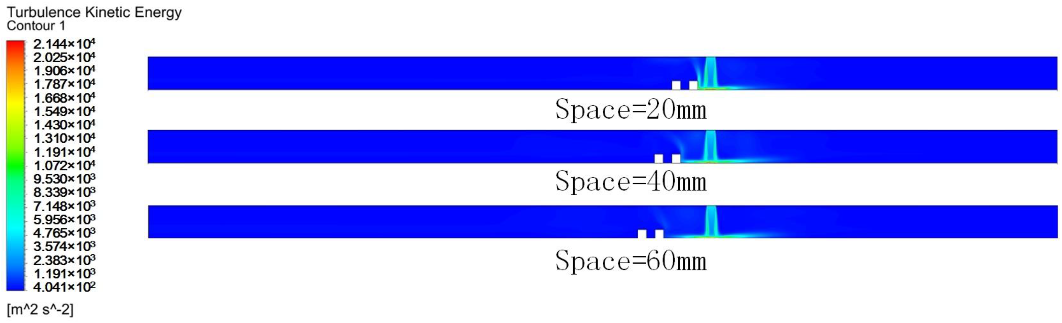
H, respectively. The distance from the first-row rib to the closed wall is 420 mm, and the spacing of the ribs is 25 mm. In case 1, it is considered that the streamwise distance from the holes to the front of the first-row rib is various, and is set as 20 mm, 40 mm, 60 mm, respectively. In case 2, nine different sizes of the rectangular ribs are designed for choosing the best one for improvement of cooling efficiency.
3. Mathematics & Materials
In these cases, each hole angle with different coolant injection orientations are confirmed in the former researches, so the coolant inlet orientation is orthogonal to the wall. According to the working condition of one F model gas turbine, the temperature and the mass flux rate of the mainstream flow is set as 1300 K and 32.72 kg/s, respectively. The turbulence intensity is set at 5%, which can be estimated based on the mass flow rate, area, hydraulic diameter of the gas inlet, and gas viscosity. In order to reduce calculation, the number of impact hole was reduced to only three in the coolant chamber. Therefore, the value of pressure on the jet hole inlet is used as the initial conditions, which is set at 1.821 MPa. The pressure recovery coefficient is given as 0.95, which means that the ratio of pressure between the inlet and outlet of transition piece with smooth surface. The turbulent intensity on the coolant inlet is 10%. Details of boundary conditions are ascertained in
Table 1 [
13]. In the mainstream chamber, it is assumed that the main streamflow is a mixture of N
2, O
2, H
2O, and CO
2, as well as rare gases. In another chamber, air as the cooling flow is used for all of the simulations. The material of the thermal surface is using Nimonic 263 (Hucheng industry (Shanghai) Co., Ltd, Shanghai, China), for which information could be found from internet.
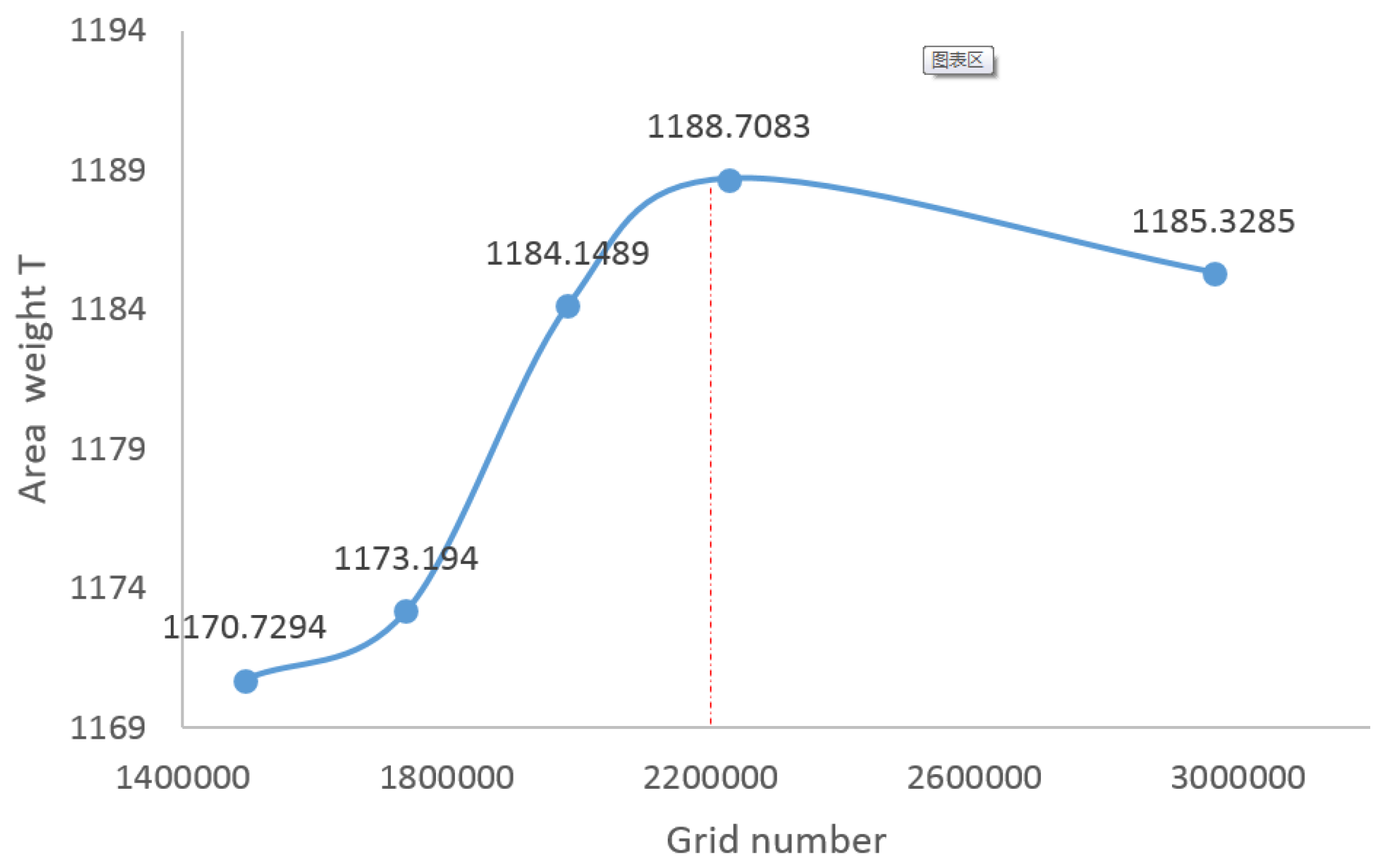
The model is a computational domain that is made up by hexahedron meshes in the software, ANSYS-ICEM, version 18.0. In
Figure 3, the grid sensitivity test for the simplified two-chamber model with the biomimetic thermal surface are carried out. When the number of cells increase from 2,227,680 to 2,962,080, the area weighted average temperature is declined by 0.3%. The calculation deviation of temperature is insignificant on further increasing the numbers of cells. Thus, 2,200,000 cells are used as a grid independent mesh for obtaining the solution variables in our further simulation.
In order to intuitively acquire the quantity of heat that is taken away in the process of heat exchange in the cooling chamber, the flow rate temperature
, which is provided as an indicator that is computed by the product of flow rate and temperature, and it is defined as
where
is the density of the coolant and
is the facet velocity on the selected field. Also, the heat transfer coefficient can be defined as
which serves as an indicator to value the performance of impinging cooling. In Equation (2),
is the number of group and
represents the group of smooth thermal surface. Also,
is defined as
In Equation (3), and are the flow rate temperature on the outlet and the inlet surfaces.
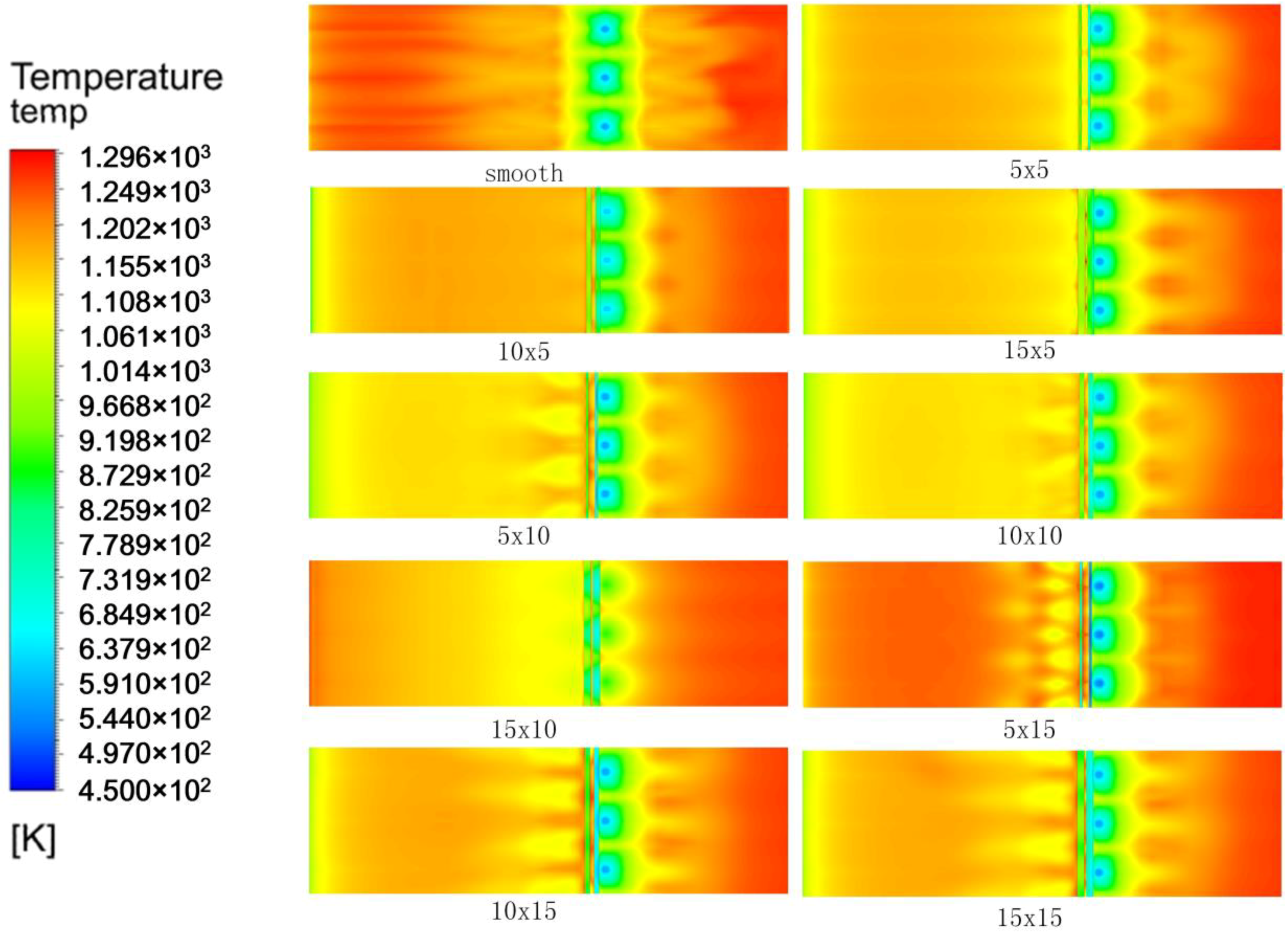
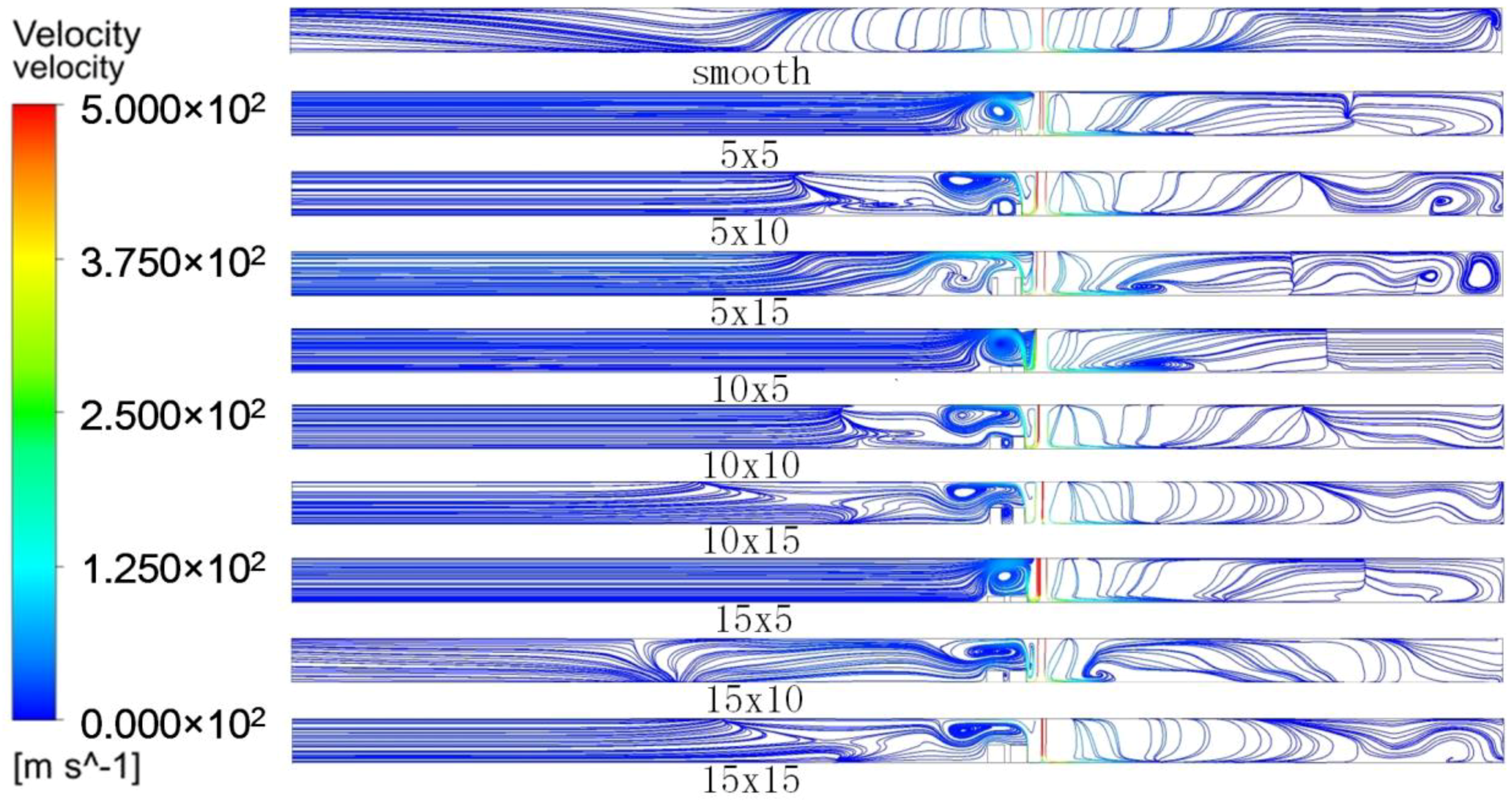
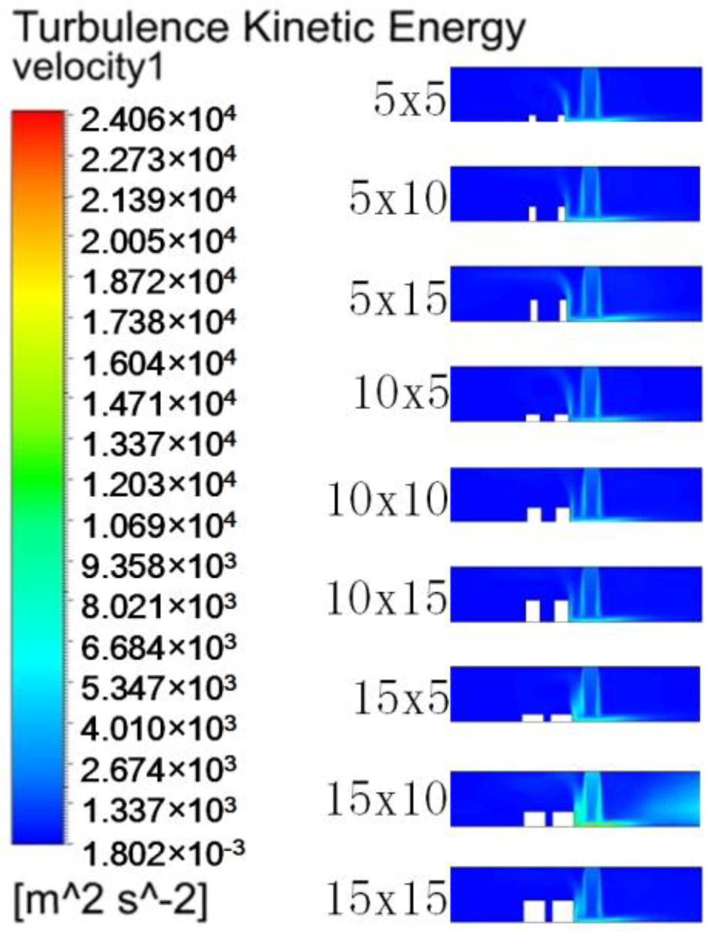
In order to describe the contour of temperature on thermal surfaces and the distributed field of turbulent kinetic energy in the coolant chamber, this study is using the control-method, which is a commercial CFD code, ANSYS-FLUENT 18.0. The flows in these simplified calculated models are steady, Newtonian, three-dimensional, incompressible, turbulent, and behave according to three fundamental laws: continuity, and the conservation of momentum and energy. The realizable k − ε turbulence model with the enhanced wall function is chosen to simulate the flow behaviors and the convective heat transfer enhancement on the biomimetic thermal surface. All of the runs were solved on a workstation with sixteen cores i7 3.6 GHz CPU. The decreasing of the mass residual by 85% percentage is chosen to be the standard of convergence tolerance during 2000 solving iterations.
5. Conclusions
In this study, it has been investigated that the convective heat transfer and the coolant flow characteristics on the biomimetic thermal surface by using the realizable models. The effect of rib turbulators position is discussed on the thermal surface, the variable, as well as the height and width of the rib turbulators is also studied by the comparison. The major findings of the present study are summarized below:
The biomimetic thermal surface inspired by Alopias’ branchial arch can improve jet impingement cooling.
The effect of the streamwise distance from the holes to the first-row rib are studied on the biomimetic surface. It can be confirmed that the outlet flow rate temperature is almost the same, when the streamwise distance increases from 20 mm to 60 mm. So, the streamwise distance is not a significant factor.
Since ejected into the cooling chamber at a high speed, the coolant airflow is impacted by the rib turbulators. The simulation results show that the best size of the rib turbulators can improve the heat transfer efficiency to 32.5%, When comparing with the results of the smooth thermal surface.
The above conclusion and the fluid characteristics analysis provide a new sight of bionic structural design on heat transfer, especially for the gas turbine and manufacturing machines, which confront a similar severe working condition. We hope both of different researcher could make much deeper research.


