1. Introduction
Architects and engineers working in ancient cities very often have to deal with situations in which historic buildings and alike are affected by pathologies related with ground conditions. Eventually, if soil is not improved, the pathologies can progress to the point where the conservation of these cultural assets may be jeopardized.
In most cases, due to their age, these structures are on well-consolidated foundations, but its strength properties become degraded by man-made activities [
1]. The soil supporting the foundation changes over time and this produces additional stress on the foundation causing deformations that are very different than the ones that prevailed during many years.
Sometimes, intervention to change the use of the building gives way to a new distribution of loads which generates differential settlements, but other times, degradation of soil conditions is the main cause. Changes in the mechanical properties of the soil supporting the foundation may be caused by:
- -
Leaks or cracks in water pipes change the soil moisture content.
- -
Fluctuations in the water table in the area.
- -
Biological activity as growth and rotting of roots.
- -
Physical and chemical degradation of buried foundation materials.
Soil improvement is the first step to start repairing these pathologies [
2]. This can be achieved by many ways, but now it is available a non-destructible low-disturbing technology that consist of injecting expanding polyurethane resin. This technology and its recent application to historic buildings are described in this article.
2. General Description of the Technology
Traditional injection techniques use a mixture of water and cement with additives. They are non-expanding resins. Soil improvement is achieved by applying pressure to the grout when liquid, and void reduction or consolidation is achieved by the volume eventually occupied by the injected grout.
Injecting expanding polyurethane resins is different due to the chemical nature of its components: polyurethanes. In fact, they require no injection pressure. The solidified resin achieves a natural balance with the surrounding soil when the swelling pressure of the resin as a result of the reaction coincides with the average confining pressure of the soil. This way, the mechanical properties of the ground can be improved.
2.1. Basic Concepts of Expanding Polyurethane Resin
Expanding polyurethane resins are produced by the exothermic reaction between a polyol and an isocyanate when combined in volumetrically established proportions. During the chemical reaction, a large amount of carbon dioxide is produced which causes the volumetric expansion of the mixture and formation of a spongy structure where the gas bubbles are trapped. The production of carbon dioxide requires the presence of water which reacts with isocyanate group. In the absence of water, a chemically inert swelling agent with a low boiling point is used, which is vaporized consuming part of the polymerization heat.
The mixture changes from a liquid to a solid and hardens in a very short time. The reaction time, which depends on the particular resin and catalysts used, is influenced by the temperature of the admixed components. By controlling the temperature of the components, it is therefore possible to speed up or slow down the reaction time.
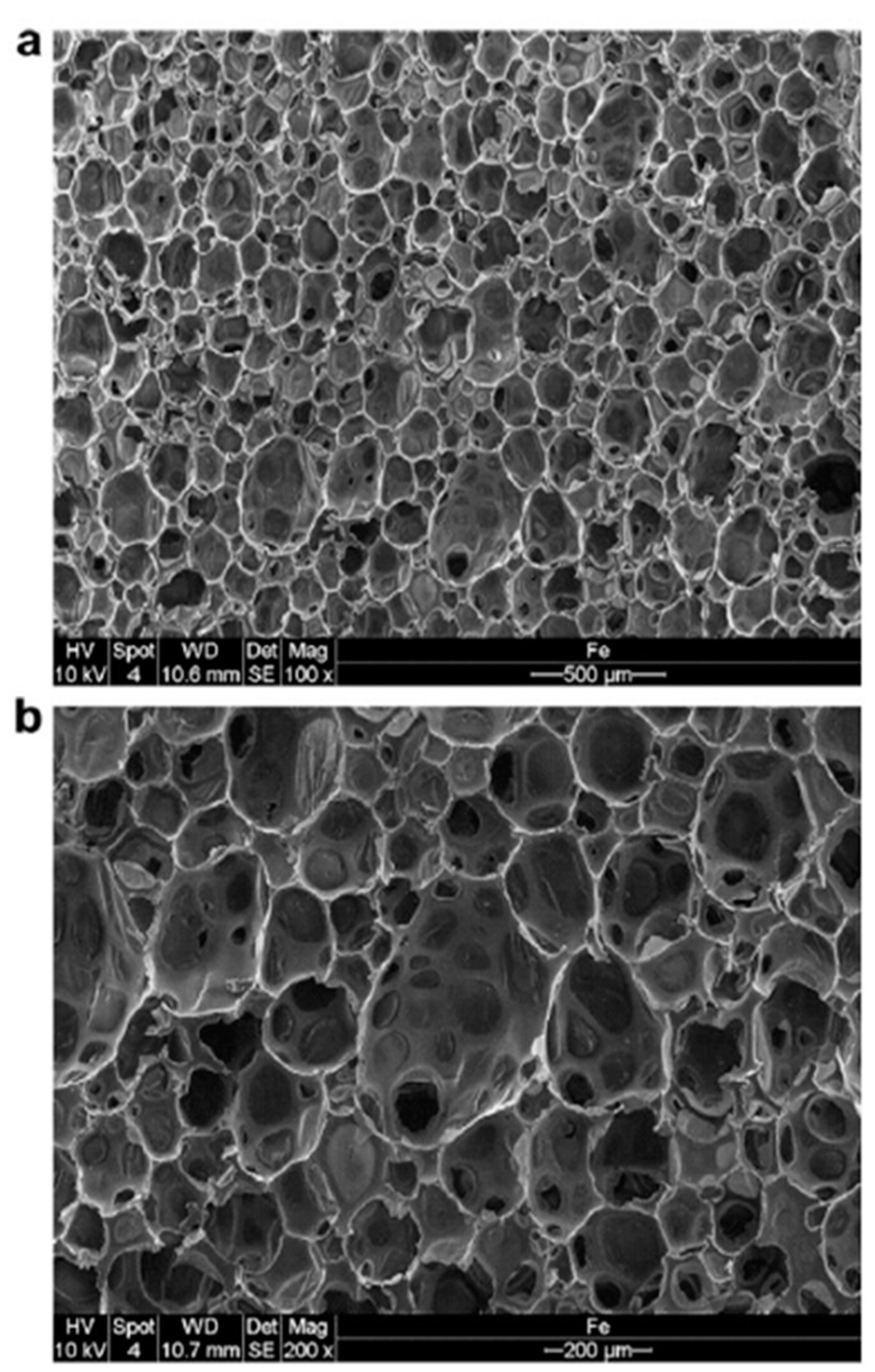
The pressure exerted during the swelling and the final position of the resin depends on the expansion capabilities of the gas in the bubbles before it hardens. The “closed cell” structure of the expanded resin is shown in
Figure 1. The images were obtained using an electron microscope [
3] and show the microscopic structure of the Geoplus resin used by Uretek [
4] under free swell conditions corresponding to a density equal to 37 kg/m
3. The density of the liquid mixture is equal to 1070 kg/m
3, very close to that of water. Under these conditions, the expanding volume is equal to 30 times the original volume of the mixture [
5,
6].
The mechanical properties of the resins can be found in the studies conducted by accredited European laboratories. Of particular note is the fact that the mechanical resistance of the expanded and hardened resin depends on the degree of expansion [
6]. For specific gravity between 0.5 and 3.3 kN/m
3, the resistance values are between 0.2 and 6.0 MPa. The elastic modulus of the resin is comparable to that of any type of soil where a foundation is built. It can vary between 10 and 80 MPa depending on the density obtained after polymerization of the resin. These values are comparable to the modulus of average elasticity of soils that have been obtained from the bibliographic references of the main Spanish authors [
7,
8],
Table 1. Consistent with the above, it can be concluded that after injecting expanding polyurethane resin the volume of treated soil does not modify the rigidity or distribution of force under the treated area [
9]. In other words, there is no creation of “hard points” in the soil and the procedure for injecting resin can be considered suitable for partial or localized treatment [
10].
2.2. Injection Technology
Injection technology allows you to inject polyurethane resin into the soil at different depths through small perforations, causing minimal disturbance to structures and the overlying ground in order to solve problems related to the capacity of the ground under foundations. The treated soil is consolidated in a vertical or sub-vertical direction thanks to a succession of low pressure injections of the resin under the foundation. Once the resin injected into the soil expands, the soil interface can be re-established at different depths and in areas where the admissible stress values are low (see
Figure 2). A better load distribution is thus achieved and the tension peaks under the foundation are limited.
2.3. Injection Methodology
The methodology and method procedure are based on drilling holes less than 30 mm (typically between 12 and 26 mm), spaced between 50 and 150 cm apart.
Figure 3a. Metal pipes are then inserted into these holes down to the established depths,
Figure 3b, and the expanding resin is injected into the soil through the pipes. The injection is controlled following specific protocol. The two basic points of this injection protocol include the injection head of the resin,
Figure 3c and the laser level that controls the lifting of the structure,
Figure 3d.
The resin is injected into the soil in a liquid state [
11]. Almost instantly, a chemical reaction is triggered causing an increase in volume and the resin changes from a liquid to solid state. The expansion pressure of the resin can reach 10.000 KPa. The reaction begins and ends very quickly. The resin reaches its final physical-chemical characteristics in a few seconds.
When the resin penetrates the soil to be treated and increases in volume, it compresses the soil in all directions. This radial expansion is favored by the pathways that offer the least resistance. The resin continues to expand until the soil prevents any further radial compression. At that point, the only possibility for expansion is an upward displacement of the soil [
12].
When this initial lifting is observed, it means that the consolidating action is being directed vertically upward and that this is the direction that offers the least resistance, while the surrounding soil offers greater resistance in respect of the decrease in the structural load, which means that the foundation soil has been compacted enough to withstand not only the increase in static loads, but also the loads created by the lifting [
5,
6].
This initial rising of the structure (tenths of mm), is what makes it possible to confirm the effectiveness of the method in real time. When the resin is injected at different depths, the injection usually begins with the top level, proceeding to the next level once the resin mixture hardens.
During the injection, the amount of mixture used is measures at each injection point and compared with the nominal consumption for the project. After the injection, a laser level is used to detect any vertical movement of the treated structure. This is the only way to check the effectiveness of soil treatment in real time.
3. Historical Setting of the City of Cuenca and the Building under Study
Founded by the Romans more than 2000 years ago, Cuenca is one of the most ancient cities on the Iberian Peninsula. The City was declared a World Heritage Site by The United Nations Educational, Scientific and Cultural Organization in 1996 because of its magnificently conserved original urban landscape: a medieval fortress, civil and religious monument from the 12th to 18th centuries and the exceptional blending of the city with the breath-taking natural environment.
The city is enclosed by a wall of Arabic origin, part of which has been conserved, along with an entrance. Cuenca’s historical monuments include the remains of a Castle (12th century), the Arabic Mangana Tower, the Cathedral (12th to 18th centuries) the Convent of the Salves (16th century), the Hanging Houses (11th to 15th centuries) and St. Paul’s Bridge (16th to 20th centuries).
During the urbanistic and architectural splendor of the Late Middle Ages (11th to 15th centuries), Cuenca rose up as a powerful industrial city which experienced notable economic success thanks primarily to its textile and livestock industries. The cloth trade and rug production brought with them an extensive transformation industry that included laundering, dry cleaning and weaving. During the 19th century the city withstood a relevant growth. At that time, Rey-Alfonso VIII Street was the main thoroughfare connecting the new neighborhoods to the Plaza Mayor.
In modern days, the city still enjoys a great activity as an important economic and cultural center. The city combines modernity with the old flavor of its entire history, and their citizen are proud and compromise with keeping the old buildings as part of their heritage.
3.1. Building Features
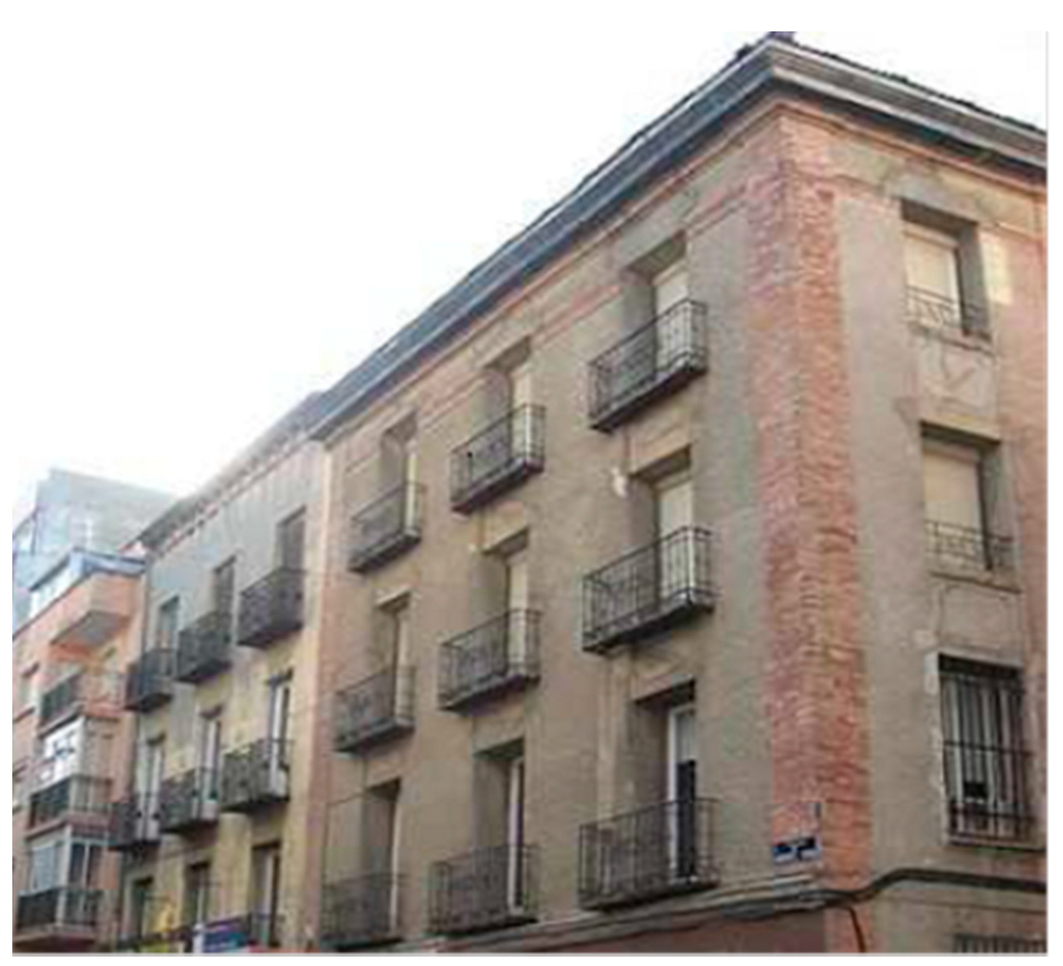
The building that was repaired stands at the top of the city’s historic quarter, specifically at Street Sánchez Vera nº 11. The building is over 130 years old. It is a four-level construction with no basement (
Figure 4). It is a wooden structure with reddish-hued solid brick facing.
3.2. Pathologies Observed
The pathologies were caused mainly by differential settlement, which were compromising the preservation of the entire structure [
13]. According to the available information, the settlement was caused by successive breakdowns in the sewer system the previous years, with water changing the moisture content of soils at building’s foundation.
In this case, the foundation reinforcement was aimed at improving soil density in order to stop movement and to recover bearing capacity, prior to begin the planned renovation of the entire building.
4. Design and Dimensioning of the Intervention
Site investigation showed that the building foundation consists of a spread footing made of bonded stone masonry. The depth of the foundation was about 1.0 m. The footing was embedded on a man-made fill layer. The total thickness of this layer was 1.7 m, so foundation was bearing on this low-strength poor-quality layer, with values of N10 (Dynamic Probing Medium) between 1 and 30.
Underneath, just below the man-made fill, there was the untouched soil, that consists of hard marly-clay layer. This layer extended belong the stress bulb of the foundation.
This layer distribution, where an impervious clay layer is below a more permeable layer, facilitates water to keep retaining on the upper man-made fill and stay there for long period of time, giving place to soften and even collapse by degradation of local areas.
The collapse of those areas generates differential settlement in the buildings, follows by cracks and fissures at a 45º angle to the ground, with a stepped course typical of brick masonry.
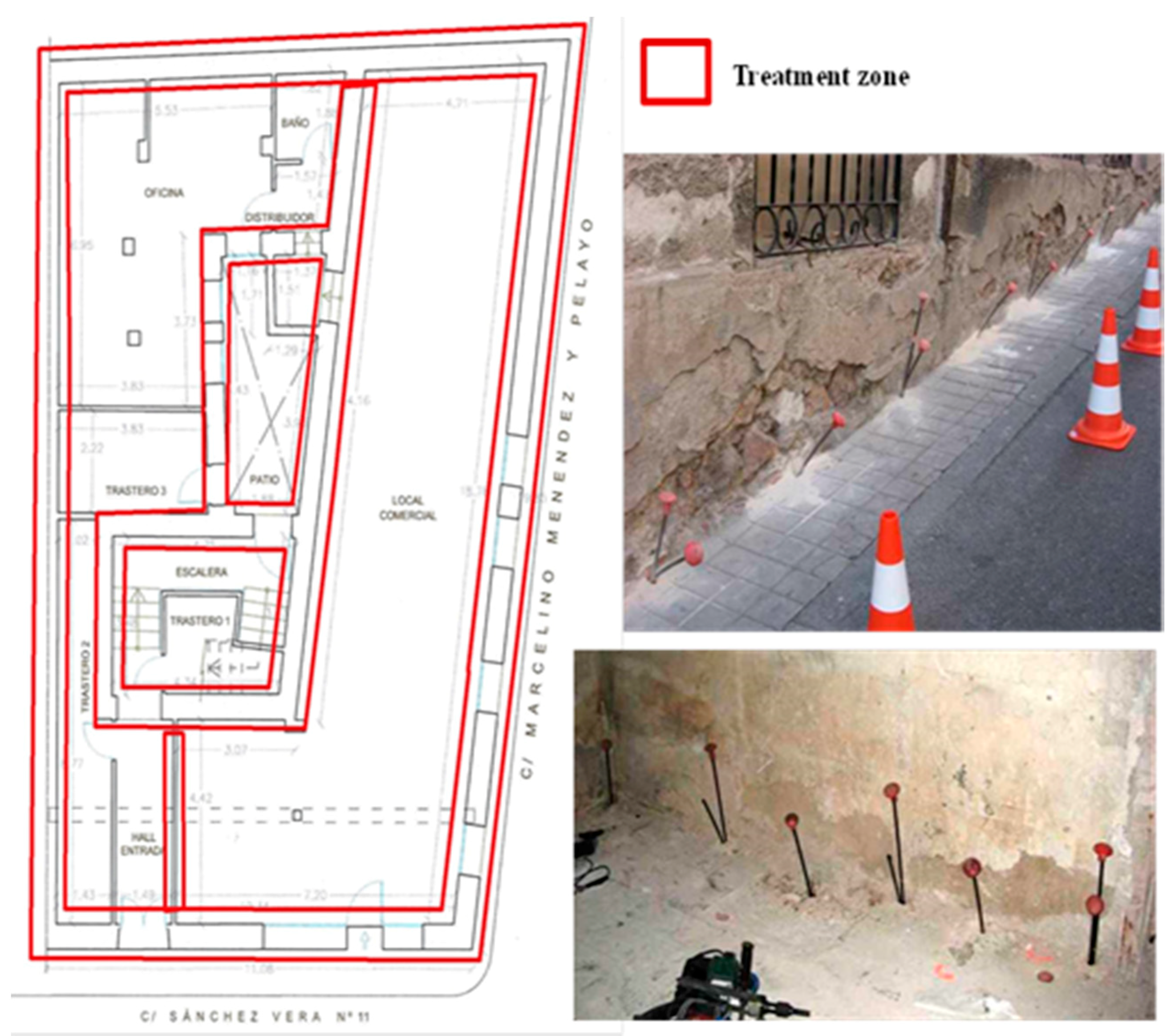
Zones to be treated by resin injection are usually chosen based on the location of the damage; however, in this case, as the pathologies were all over the building, the entire foundation was treated. Nevertheless, resin admission is a quantitative index of the soil conditions at each point.
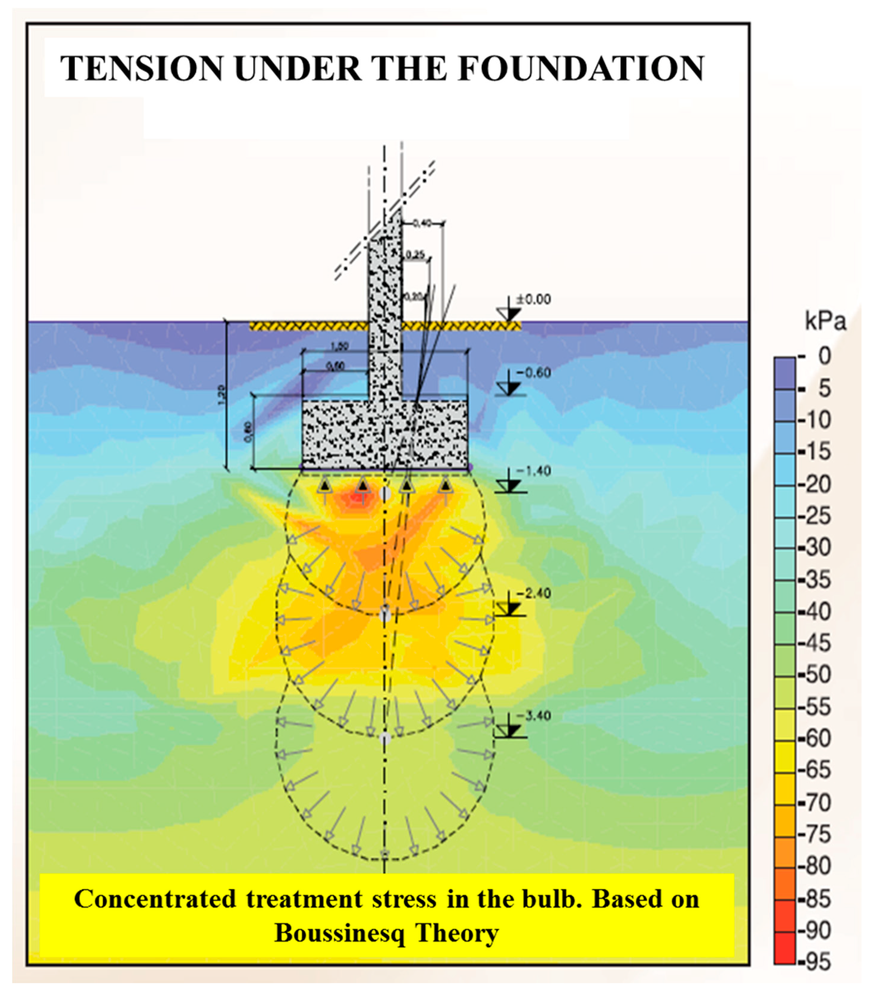
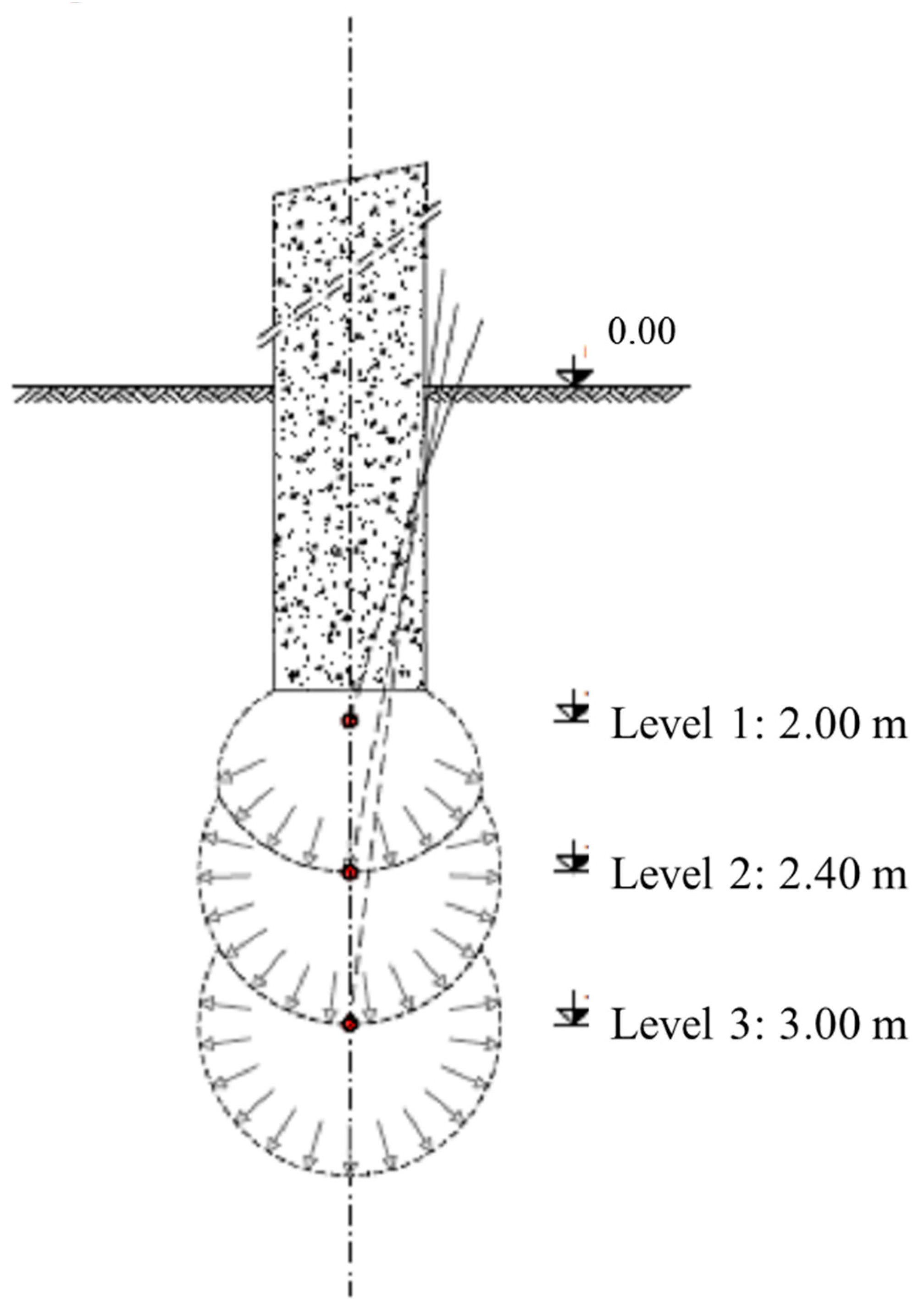
The treatment should be limited to the area of influence of the foundation (Boussinescq bulb) or to a certain “level” to be determined based on the available geotechnical information. Based on these conditioning factors, the treatment area for this building was limited to a depth of 3.0 m below the street level, that means 2.0 m below footing bearing surface. (
Figure 5).
The intervention was divided into two phases:
Phase I. Surface compaction. Injecting the first meter below street, around the spread footing in order to improve the geomechanical characteristics of the foundation, and filling the gaps between the foundation and the soil.
Phase II. Deep consolidation. Injections performed at different depths (3 levels) into the soil affected by the building loads.
The number of injection levels is based on the depth of the degraded soil defined by the site investigation. As a starting point, the concept of pressure bulb for shallow foundation may be considered. Injection levels are usually separate between 0.5 and 1.0 m,
Figure 6.
If several injections are made very close to each other along a vertical line, which is what we want to show in
Figure 2 and
Figure 6, it will happen that in the first part of the expansion process, when the internal pressure increases and the ground responds elastically, later it will begin a plastic deformation until reaching the limit of the internal pressure. It is evident that when this pressure limit is reached, the resin will solidify. This process is almost immediate and its duration is several seconds.
5. Foundation Underpinning Using Resin Injection
The underpinning of the foundation was performed by injecting expanding polyurethane resin. The resin injection phases included in the protocol:
5.1. Drilling and Installation of Injection Pipes
Small electric rotary drillers are used to make the holes for the installation of the injection pipes through the foundation (see
Figure 3). This drilling system does not transmit vibrations to the structure. The perforations are 26 mm in diameter and were made with screw augers of different lengths to reach the exact depth. For this case the injection levels were 2.00, 2.40 and 3.00 m. The perforations were separated horizontally 1.50 m.
Once the foundation is pierced, metallic 12 mm diameter pipes were installed by vibration. These pipes are afterwards used for injection so they are equipped with close valves at the toe to prevent the obstruction of the pipe as it is being installed in the soil. The length of the injection pipes was determined based on the theoretical injection depth and the inclination of the pipe relative to the vertical axis. Allowed tolerance for deviations is ±10 cm.
5.2. The Resin Injection Process
Once the pipes are installed, the injection of the resin begins immediately. The resin is injected using and “injection gun” that is fitted to the upper end of the installed injection pipe. The two components of the resin are transported separately to the “injection gun" and mixed under high pressure in a chamber located at the rear. This ensures a perfect mixture of the two components before the mixture is added to the injection pipe and then into the soil.
This process continues at each injection point until the lifting of the structure is first observed. Lifting is the element that makes it possible to check the injection efficiency in real time.
5.3. Instrumentation and Control of the Injection
A laser level with accuracy up to 0.1 mm was used to control the lifting of the structure, which also made it possible to detect vertical movement during the injection. This is considered a real time monitoring (see
Figure 3).
The laser level was positioned at a certain distance from the injection point to prevent it from being affected by the injection process. The set-up consists of the level and various targets attached to the structure to be treated. These targets detect variations in the lift respect to the fixed horizontal reference plane set by laser.
The interruption or cessation of the injection process is determined based on this monitoring, which allows controlling lifting and to avoid unwanted movement. The best evidence of the effectiveness of the injection is the liftings recorded in the control systems.
6. Results Obtained
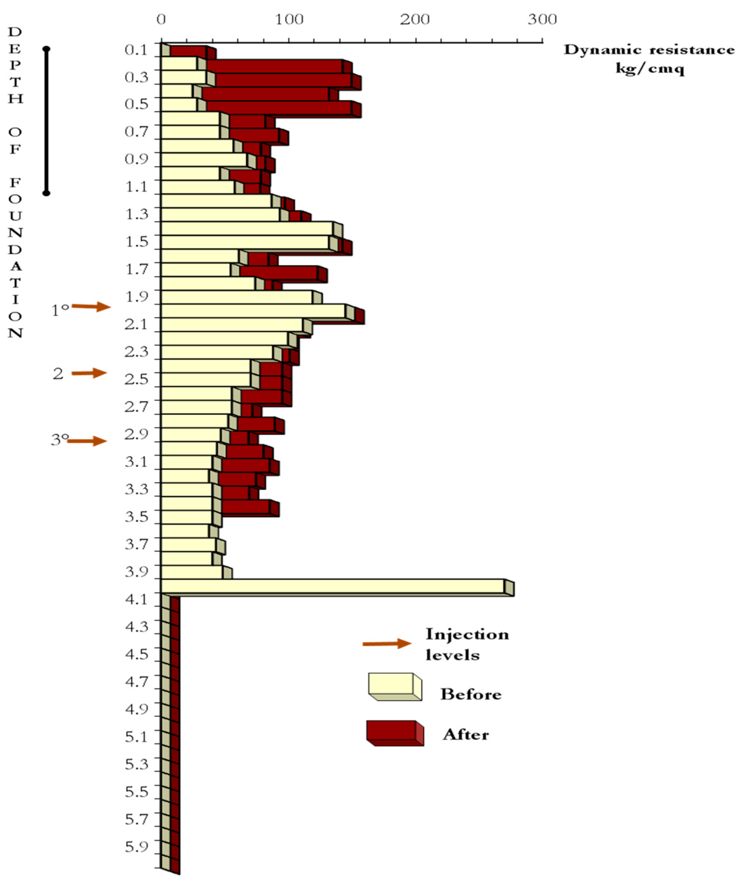
Following the injection, a geotechnical study was conducted using DPM (Dynamic Probing Medium) (AENOR-CEN, 1993) in order to verify the improvements achieved in terms of the load-bearing capacity of the soil. These dynamic penetration tests were carried out at the same site and with the same equipment that was used to characterize the soil prior to injection. This comparative study shows the improvement to the soil in terms of penetration resistance, which is indicative of the load-bearing capacity of the treated soil (
Figure 7).
7. Conclusions
In traditional injection techniques, a mixture of water and cement with additives, or non-expanding resins, is generally used. The design objectives of these treatments are controlled by the nature and quantity of the components present in the mixture and the injection pressure, which determines the area of influence of the consolidation [
14].
The injection of polyurethane resins has a different behavior, due to the chemical nature of its components, polyurethanes. In fact, they do not require any injection pressure and during the synthesis reaction a certain amount of carbon dioxide is generated which causes the volumetric expansion of the mixture (
Figure 1). The solidified resin reaches the natural balance with the surrounding soil, when the pressure of swelling of the resin, resulting from the reaction, coincides with the average pressure of the confinement of the ground.
The capacity of propagation of the resin in the different types of soil, can be established according to the following criteria. In gravels and sands the propagation is, mainly, by impregnation of the intergranular spaces. In clays, the voids and fractures present in the macrostructure of the soil are saturated by the resin, or compressed by the swelling pressure during the expansion of the mixture.
The injection of expanding polyurethane resin into the soil is a technology for soil improvement that is also used for correct differential settlement in building. It is noteworthy that, because is a non-destructive method, this technology is especially suitable for historic buildings which are part of the country’s architectural heritage.
The principle of the technology is based on the injection of a certain volume of expanding polyurethane resin into the soil, below the foundation bearing surface which then expands, displacing the soil around the injection site [
15,
16]. The expansion is accompanied by a reduction in swelling pressure and an increase in the average confining stress. The process stops when it reaches the equilibrium pressure.
The resin penetrates into the terrain to be treated, increasing in volume and compressing the soil in all directions (radial expansion) favoring the pathways that offer the least resistance [
3,
4]. The resin continues expanding until the soil prevents any further radial compression. At that point, the only possibility for expansion is an upward displacement.
This process continues at each injection point until the lifting of the structure is first observed. When the initial lifting is observed, it means that the consolidating action is being directed vertically upward and that this is the direction that offers the least resistance, while the surrounding soil offers greater resistance in respect of the decrease in the structural load. This shows that the foundation soil has been compacted enough to withstand not only the increase of static loads, but also the loads developed as a result of the lifting [
16].
Due to the recent implantation in Spain of this technology, it is not possible to prove the efficacy of long-term treatment (more than 10 years).
But new dynamic penetration tests and supervisions of the stabilized building are demonstrating that the mechanical properties of the treated ground continue being stable and that they have not diminished in the three years passed since the treatment.


