Abstract
The micro-electro-mechanical system (MEMS) accelerometer is widely adopted in many engineering control systems due to its extraordinary performance with high bandwidth, small size and low weight. However, massive drift caused by its insensitively at low frequency is the main factor which limits its performance. It leads to integral saturation when the feedforward method is used and hinders the improvement of disturbance suppression ability at low frequency, which is a significant factor for evaluating the closed-loop performance of a high-precision tracking system. To solve this problem, a modified disturbance observer structure and its corresponding new controller, which can improve disturbance suppression performance at low frequency by effectively rejecting more drift and weakening the occurrence possibility of integral saturation when drift exists, are proposed. Detailed analyses and a series of comparative experimental results verify that the proposed method can effectively enhance disturbance suppression performance at low frequency.
1. Introduction
The tracking control system (TCS) is widely used in long-distance communication, astronomical observation, target tracking and other scientific fields [1,2,3,4,5]. However, when applied to practical programs, the TCS suffers from some external interferences from atmosphere, ground or movable platforms such as vehicles, airplanes and ships [1,6]. In the TCS, gyroscopes and position detectors are generally used as sensors to implement a dual-loop feedback control (DFC) to stabilize the controlled platforms [7,8] Gyroscopes with a small delay are used to build a high-bandwidth inner loop and the tracking performance of the TCS mainly depends on the position information from position detectors such as a charge-coupled device (CCD). Control bandwidth and disturbance suppression ability are two significant factors for evaluating the closed-loop performance of the TCS. However, control bandwidth and disturbance suppression ability are limited by the mechanical resonance and the sensors’ performance such as the drift and time delay caused by the low sampling frequency [9,10].
In order to improve the performance of control bandwidth and disturbance suppression, the micro-electro-mechanical system (MEMS) accelerometer has been widely recommended for the TCS due to its high bandwidth, small size and low weight [11,12,13,14,15]. The MEMS accelerometer can compensate for the mechanical resonance in the acceleration feedback control loop, and is therefore utilized to enhance the stiffness of the controlled object. Tang implemented a dual-loop control by using the MEMS accelerometer and the CCD with a high bandwidth to improve control bandwidth [16]. In 2016, Tian proposed a multi-loop feedback control method (MFC) with the MEMS accelerometer, MEMS gyroscope and CCD, which successfully improved the disturbance suppression performance [17]. The overall disturbance suppression ability is the product of each single loop, hence the disturbance suppression ability of MFC is naturally better than that of DFC [18]. Moreover, the research about the disturbance suppression of the TCS is based on MFC for obtaining better performance.
To improve the performance of the TCS, the feedforward method based on direct measurement is also introduced as it can suppress most of the theoretical external disturbances [19,20]. However, it involves additional cost for another sensor and specific environments with low measurable noise. As a result, the implementation feedforward method is limited in more complex conditions due to its disadvantages. In order to avoid the extra cost and application limitations, a basic idea to suppress disturbances emerges, which estimates the influences of external disturbances independently by using the disturbances observer and then eliminates the perturbation through the feedforward method. This feedforward method was first presented by Ohnishi in the 1980s and was named the disturbance observer (DOB) method [21,22,23]. It has been applied to several engineering processes, such as robot control, the hard disk, the magnetic hard drive servo system and permanent magnet synchronous motor control [24,25,26,27,28,29]. Beyond this, Deng recommended the disturbance observer for an acceleration feedback control loop with a MEMS accelerometer, which improved disturbance suppression ability only at intermediate frequency [30].
Disturbance suppression is still a large obstacle for the good tracking performance of the TCS. One problem that has not been handled by the afore-mentioned method is that there is considerable drift caused by the MEMS accelerometer due to its insensitivity at low frequency. As a result, the drift leads to integral saturation when feedforward methods are used to suppress disturbance [30]. As such, it is hard to improve disturbance suppression performance at low frequency with the MEMS accelerometer.
To solve the above-mentioned problem, in this paper we propose the modified disturbance observer (MDOB) method to enhance disturbance suppression performance at low frequency in the TCS, which weakens the occurrence possibility of integral saturation when drift exists. We design the structure of the MDOB by changing the output node of the feedforward and present a corresponding new MDOB controller which is simple but effective. As a result, the drift rejection ability is effectively improved, making it possible to significantly improve the disturbance suppression ability at low frequency. The rest of the paper is organized as follows: Section 2 introduces the basic tracking control system and disturbance observer; in Section 3, a modified disturbance observer and its performance analyses are presented; Section 4 shows the verification experiments of this method; and lastly, concluding remarks are presented in Section 5.
2. Tracking Control System and Disturbance Observer
A typical tracking control system is shown in Figure 1, which can be used to track the movement of stars and communicate between the earth and satellites. The CCD is utilized to detect the errors between the target position and pointing position. However, the disturbance under the pedestal affects the tracking accuracy. Moreover, the frame rate of the CCD is limited. In order to improve the disturbance suppression ability and tracking accuracy, a MFC and a disturbance observer are recommended in the TCS.
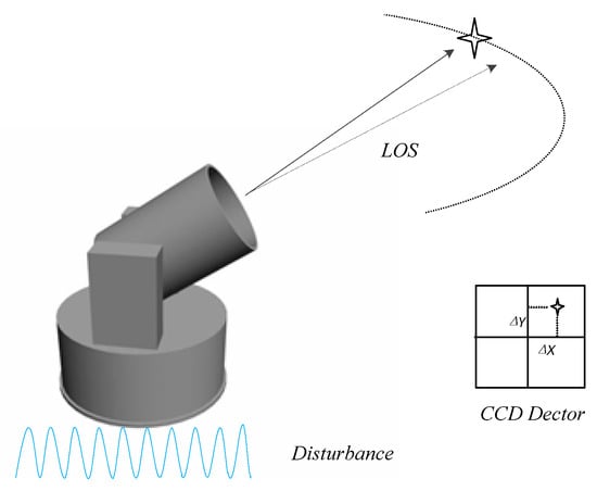
Figure 1.
A typical tracking control system.
The structure of the multi-loop feedback control system is shown in Figure 2 [13,17]. It is composed of a position feedback control (PFC) loop, a velocity feedback control (VFC) loop and an acceleration feedback control (AFC) loop. There are three kinds of sensors—the position sensor, velocity sensor and acceleration sensor—which are used to acquire the position information, angular velocity and angular acceleration, respectively.
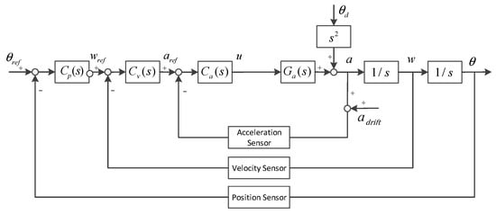
Figure 2.
The multi-loop feedback control system.
In this figure, Ga(s) denotes the acceleration controlled plant, denotes the acceleration controller, denotes the velocity controller, denotes the position controller, denotes the disturbance angle, and denotes the given target position.
In addition to the CCD, the MEMS accelerometer has also been widely used in target tracking systems in recent years due to its excellent performance. Due to its high bandwidth and specific dynamic characters, the transfer function of the MEMS accelerometer equals constant 1. As a result, the acceleration transfer function of AFC is depicted in Equation (1).
The MEMS accelerometer can also be utilized to measure the frequency characteristic up to 1 kHz, which means high-precision nominal plant can be acquired through system identification [11,12,17]. However, there is massive drift caused by the insensitivity at low frequency of the MEMS accelerometer when angular acceleration is detected. The drift makes it difficult to improve the disturbance suppression ability at low frequency with the feedforward method. The harm from the drift is especially obvious when the DOB method is introduced into the TCS with the MEMS accelerometer as shown in Figure 3.
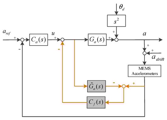
Figure 3.
A structure of disturbance observer in acceleration feedback control (AFC).
The acceleration transfer function in Figure 3 is depicted in Equation (2). It is clear that the drift rejection ability when the DOB is recommended is even worse than that of the AFC according to the comparison of Equations (1) and (2). When a DOB controller is designed, there are multiple integration elements which are used to offset the multiple differential elements in . As a result, considerable drift and the multiple integration of the DOB controller finally lead to integral saturation when the MEMS accelerometer works at low frequency [30].
where denotes the DOB controller.
Through Equation (2), it is clear that the ideal DOB controller is . As the nominal plant of the controlled object is a strictly proper transfer function, the ideal DOB controller is a non-causal system, which can be handled with a low-pass filter [29,30].
3. Modified Disturbance Observer
The reason for the occurrence of integral saturation is that there is too much drift that cannot be effectively rejected by the DOB when the MEMS accelerometer detects movements at low frequency. The key to avoiding integral saturation is that more drift of the accelerometer needs to be rejected. Therefore, we propose a creative MDOB structure as shown in Figure 4, where we change the node of feedforward by moving the output node of DOB controller from the outer loop of the nominal plant to its inner loop. Moreover, in order to adapt to this change, we then propose a corresponding new simple but effective way to design the MDOB controller, which enormously simplifies the design process of the MDOB controller and effectively improves both drift rejection and disturbance suppression performance.
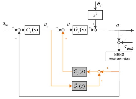
Figure 4.
Control structure of modified disturbance observer (MDOB) in AFC.
After substitution, it is easy to obtain the following transfer function of the AFC with the MDOB:
Due to , Equation (6) can also be simplified as Equation (7). As shown in Equation (7), the disturbance transfer function and drift transfer function can be described as Equations (8) and (9), respectively. Compared with the acceleration feedback closed loop without the DOB or MDOB shown in Equation (1), is totally changed by the recommended MDOB. This means that the drift rejection ability can be greatly improved by designing the MDOB controller. Beyond this, the tracking performance is not influenced by introducing the MDOB into the AFC, as shown in Equations (1) and (7).
Focusing on the changes in the disturbance transfer function and drift transfer function with the MDOB, we should design a MDOB controller that is beneficial for both drift rejection and disturbance suppression. A new type of MDOB controller , which is a causal system and might be a very suitable one, is depicted in Equation (10). It is clear that there is only one parameter that needs to be determined, meaning the design process will be enormously simplified.
After the design, the overall drift rejection ability with the MDOB is shown in Equation (11). It is an inertial element and its inertia time constant is . The disturbance transfer function with the MDOB controller is shown in Equation (12), and the disturbance suppression ability at low frequency can be enhanced from constant.
where denotes the inverse of nominal plant .
In general, the bandwidth of the AFC loop is designed as up to 200 Hz, hence the cut-off frequency of its drift rejection is also about 200 Hz. According to the comparison of Equations (1) and (2), the drift rejection ability with the DOB is even worse when the DOB is introduced. In other words, the cut-off frequency of the drift rejection with the DOB is larger than 200 Hz. By contrast, the cut-off frequency of the drift rejection with the MDOB is much smaller for constant , which means that it can bring much better drift rejection ability as shown in Figure 5.
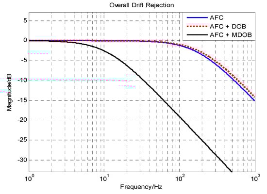
Figure 5.
The comparison of overall drift rejection.
Under the MFC structure as shown in Figure 2, the disturbance suppression ability of the position loop is depicted as Equation (14), and the disturbance suppression ability of the position loop with the MDOB is shown in Equation (15). Through the comparison of Equations (14) and (15), the disturbance suppression ability of the position loop is changed by introducing the MDOB to the MFC, and the improvement can be represented as .
According to the previous analyses, we can obtain the enhanced part of the disturbance suppression ability of the MFC with a MDOB controller, which is equal to , as shown in Figure 6. In fact, the drift rejection performance determines whether the enhanced part of the disturbance suppression ability can be achieved. Except for the multiple integration elements to offset the multiple differential elements in , the MDOB controller even includes a further integration element. If there is too much drift left when the MDOB is utilized, it will be extremely easy for the multiple integration elements of the MDOB controller to lead to integral saturation.
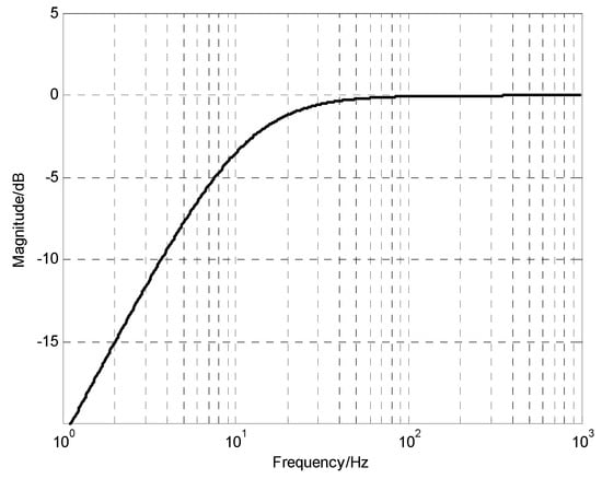
Figure 6.
The enhanced part of disturbance suppression ability with the MDOB.
Fortunately, benefiting from the improvement in drift rejection ability with the MDOB, much more drift produced by the insensitivity at low frequency of the MEMS accelerometer is rejected. As a result, the possibility of the occurrence of integral saturation becomes much lower, and this means that we can enhance the disturbance suppression ability at low frequency, which was somewhat difficult to achieve before. In addition, it is obvious that if constant increases, the disturbance suppression ability will be better but the drift rejection ability will become worse according to Equations (11) and (12). Therefore, there is a trade-off between disturbance suppression and drift rejection which depends on the specific characters of different types of MEMS accelerometers.
The robustness of a system refers to the sensitivity of the system to parameter changes, which is also an important factor for evaluating the control performance. Moreover, the sensitivity functions of the AFC and the AFC with the MDOB are as follows:
where
It is clear that , which means that applying the MDOB to AFC can also improve the robustness of the traditional AFC structure. The control system with the MDOB and AFC will suffer less from the accidental parameter changes of a controlled plant than those with only the AFC.
4. Experimental Verification
The experimental devices of the TCS are shown in Figure 7. To verify the analyses above, we used two TCS platforms both driven by voice coil motors. One of them is called a stabilization platform, which is used to stabilize the laser light. The other one is called a disturbance platform and is utilized to simulate external disturbances. The stabilization platform is mounted above the disturbance platform. Since both of the platforms are two-axis systems, we only focused on one axis due to their symmetry. The laser light that comes from the light source is reflected using a rotating mirror and then detected using the CCD (TMC-6740CL, NI Corporation, Austin, TX, USA). The CCD calculates position errors between the laser light and the center position of the CCD. The MEMS accelerometers (Model 1221, SILICON DESIGNS, Seattle, WA, USA) and the MEMS gyroscopes (XW-FG70, Starneto, Beijing, China) are mounted on the stabilization platform to acquire the angular acceleration and velocity, respectively. The CCD works at a 100 Hz sampling rate with a time delay of two frames, and the other sensors all update at 5000 Hz. The simulated disturbance is set as a sinusoidal signal of varying frequencies produced by a dynamic signal analyzer (DSA). To detect the disturbance suppression performance of the TCS, the stabilization platform works on the closed-loop mode and the disturbance platform works on the open-loop mode.
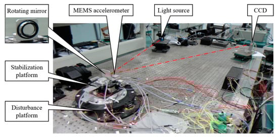
Figure 7.
The experimental devices.
As shown in Figure 8, the open-loop acceleration response of the TCS is measured using a DSA which scans for 1–1000 Hz. The frequency characteristic at low and intermediate frequency can be measured in high precision because of the high bandwidth of the MEMS accelerometer [11,12].
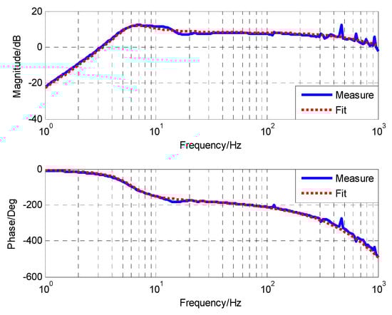
Figure 8.
Open-loop characteristic acceleration response of electro-optical system.
The nominal plant of acceleration open-loop object, which is acquired by identifying the result of the DSA, is depicted in Equation (19). The controller of the acceleration feedback control loop is designed as Equation (20). Its integration element is used to partly offset the differential elements and resonance in . Adding quadratic integration elements in can easily cause integral saturation. As the acceleration feedback control loop has largely improved the characters of the controlled object, the controllers of the velocity feedback control loop and position feedback control loop could be simply designed as proportion-integration (PI) controllers, as presented in Equation (21).
According to the analyses in Section 3, drift rejection ability can be improved by introducing a MDOB. However, the enhancement of disturbance suppression and the improvement of drift rejection are contradictory according to Equations (11) and (12). Different types of MEMS accelerometers have different characters which affect the suitable values of constant . After adjustments, one of the suitable values of is constant 70, and the MDOB controller is designed as follows:
In order to show the influence of the drift of the MEMS accelerometer, the DOB method is also used in the electro-optical system. Quadratic integration is not utilized in the DOB controller to avoid integral saturation and the DOB controller is designed as Equation (23) according to Reference [30].
In order to verify the impact of the MDOB under actual environments where disturbances are mostly at low frequencies, some experiments, the results of which are shown in Figure 9, were carried out. The target position is and disturbances consist of sinusoidal signals including 2 Hz, 5 Hz, 15 Hz and 50 Hz. The root mean square (RMS) of the MFC, the MFC with DOB, and the MFC with MDOB is , and , respectively. The DOB method has little improvement, because it can only enhance disturbance suppression ability at intermediate frequency. Moreover, the results prove that the MDOB method can largely improve disturbance suppression ability at low frequency, which is much more suitable for real conditions.
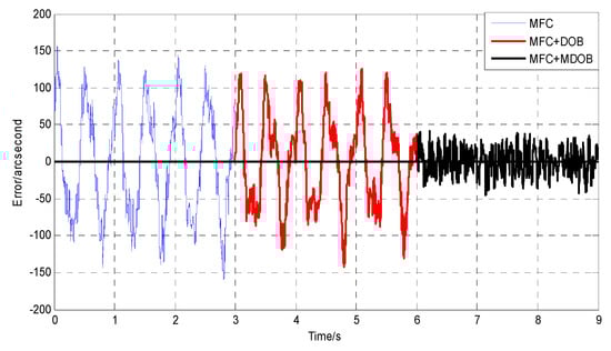
Figure 9.
The stabilization errors with given superimposed disturbances.
After that, we can also compare the disturbance suppression abilities in the frequency domain. As shown in Figure 10, it is obvious that the disturbance suppression ability at low frequency is greatly improved by introducing the MDOB to the AFC, which is different from the improvement at intermediate frequency by using the DOB. The reason for the low enhancement of disturbance suppression at intermediate frequency with the MDOB is that the enhancement of disturbance suppression and the improvement of drift rejection are contradictory according to Equations (11) and (12). If constant increases, more disturbance will be suppressed but less drift can be rejected, and the insufficient drift rejection ability will also lead to integral saturation. Therefore, there is a limit to the improvement of disturbance suppression, which is related to the specific characters of different types of MEMS accelerometers.
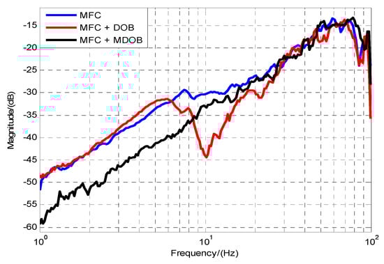
Figure 10.
The disturbance suppression comparison in the frequency domain.
The advantage of the MDOB is that although the improvement at intermediate frequency may not be as good as the DOB, the improvement at low frequency is significantly better than the DOB. As such, it is excellent for high-precision tracking systems mainly working at low frequency when the MEMS accelerometer is utilized. For instance, the bandwidth of the position loop of the electro-optical system is about 10 Hz, hence the improvement of disturbance suppression ability at low frequency is significant, which means that we can obtain much higher tracking precision at low frequency. By recommending the MDOB method and adopting a corresponding MDOB controller, we successfully improve the disturbance suppression ability at low frequency and overcome the problem of massive drift caused by the insensitivity of the MEMS accelerometer. Finally, the experimental results have exactly proved the previous analyses.
5. Conclusions
In this paper, we mainly focused on how to improve the disturbance suppression ability at low frequency in a high-precision tracking control system, which is hindered by the drift caused by the insensitivity of the micro-electro-mechanical system (MSMS) accelerometer. A MDOB structure and the corresponding MDOB controller are proposed and recommended into the multi-loop feedback control system to enhance the disturbance suppression ability. Benefiting from the MDOB method, the drift rejection ability is greatly promoted, which weakens the occurrence of integral saturation and makes it possible to improve the disturbance suppression ability at low frequency. To verify the validity of the method, a series of comparative experiments based on a tracking control system were implemented. The results show a significant improvement in disturbance suppression ability at low frequency with the MEMS accelerometer and confirm the effect of the MDOB method.
Author Contributions
Conceptualization, J.D. and W.R.; Formal analysis, J.D.; Funding acquisition, Y.M.; Investigation, J.D., Y.L.; Software W.R.; Experiments, J.D. and H.Z.; Validation, J.D., X.Z. and H.Z.; Writing-original draft J.D.; Writing-review&editing, Y.M. and X.Z.
Funding
This research received no external funding.
Conflicts of Interest
The authors declare no conflicts of interest.
References
- Ulich, B.L. Overview of acquisition, tracking, and pointing system technologies. Proc. SPIE 1988, 887, 40. [Google Scholar]
- Cochran, R.W.; Vassar, R.H. Fast-steering mirrors in optoelectronic control systems. Proc. SPIE 1990, 1303, 24. [Google Scholar]
- Hilkert, J.M.; Kanga, G.; Kinnear, K. Line-of-sight kinematics and corrections for fast-steering mirrors used in precision pointing and tracking systems. Proc. SPIE 2014, 9076, 9076F. [Google Scholar]
- Watkins, R.J.; Chen, H.J.; Agrawal, B.N.; Shin, Y.S. Optoelectronic beam jitter control. Proc. SPIE 2004, 5338. [Google Scholar] [CrossRef]
- Ostaszewski, M.; Vermeer, W. Fine steering mirror for the James Webb Space Telescope. Proc. SPIE 2007, 6665. [Google Scholar] [CrossRef]
- Bigley, W.J. Supervisory control of electro-optic tracking and pointing. Proc. SPIE 1990, 1304, 205–218. [Google Scholar]
- Lee, S.; Ortiz, G.G.; Alexander, J.W.; Portillo, A. Accelerometer-assisted tracking and pointing for deep space optoelectronic communications. In Proceedings of the Aerospace Conference, Big Sky, MT, USA, 10–17 March 2001; Volume 3, pp. 1559–1564. [Google Scholar]
- Bernstein, J. An overview of MEMS inertial sensing technology. Sensors 2003, 20, 14–21. [Google Scholar]
- Germann, L.M.; Gupta, A.A.; Lewis, R.A. Precision pointing and inertial line-of-sight stabilization using fine-steering mirrors, star trackers, and accelerometers. Proc. SPIE 1988, 887, 96. [Google Scholar]
- Hilkert, J.M. A comparison of inertial line-of-sight stabilization techniques using mirrors. Proc. SPIE 2004, 5430, 13. [Google Scholar]
- Lu, Y.F.; Fan, D.P.; Zhang, Z.Y. Theoretical and experimental determination of bandwidth for a two-axis fast steering mirror. Opt. Int. J. Light Electron Opt. 2013, 124, 2443–2449. [Google Scholar] [CrossRef]
- Csencsics, E.; Saathof, R.; Schitter, G. Design of a Dual-Tone Controller for Lissajous-based Scanning of Fast Steering Mirrors. In Proceedings of the American Control Conference, Boston, MA, USA, 6–8 July 2016; pp. 461–466. [Google Scholar]
- Tian, J.; Yang, W.; Peng, Z.; Tang, T. Inertial sensor-based multiloop control of fast steering mirror for line of sight stabilization. Optoelectron. Eng. 2016, 55, 111602. [Google Scholar] [CrossRef]
- Angel, A.P.; Gerardo, G.O.; Racho, C. Fine Pointing Control for Optical Communications. Aerosp. Conf. Proc. IEEE 2001, 3, 3–1541. [Google Scholar]
- Lee, S.; Gerry, G.O. Inertial Sensor Assisted Acquisition, Tracking, and Pointing for High Data Rate Free Space Optical Communications. Aerosp. Conf. Proc. IEEE 2003, 1, 87–88. [Google Scholar]
- Tang, T.; Huang, Y.M.; Liu, S. Acceleration feedback of a CCD-based tracking loop for fast steering mirror. Opt. Eng. 2009, 48, 510–520. [Google Scholar]
- Tian, J.; Yang, W.; Peng, Z.; Tang, T.; Li, Z. Application of MEMS accelerometers and gyroscopes in fast steering mirror control systems. Sensors 2016, 16, 440. [Google Scholar] [CrossRef] [PubMed]
- Luo, Y.; Mao, Y.; Ren, W.; Huang, Y.; Deng, C.; Zhou, X. Multiple Fusion Based on the CCD and MEMS 2 Accelerometer for the Multi-loop Optoelectronic 3 System Control. Sensors 2018, 18, 2153. [Google Scholar] [CrossRef] [PubMed]
- Böhm, M.; Pott, J.U.; Kürster, M.; Sawodny, O.; Defrère, D. Delay Compensation for Real Time Disturbance Estimation at Extremely Large Telescopes. IEEE Trans. Control Syst. Technol. 2016, 25, 1384–1393. [Google Scholar] [CrossRef]
- Glück, M.; Pott, J.U.; Sawodny, O. Piezo-actuated vibration disturbance mirror for investigating accelerometer-based tip-tilt reconstruction in large telescopes. IFAC Papersonline 2016, 49, 361–366. [Google Scholar] [CrossRef]
- Nakao, M.; Ohnishi, K.; Miyachi, K. A robust decentralized joint control based on interference estimation. In Proceedings of the IEEE International Conference on Robotics and Automation, Raleigh, NC, USA, 31 March–3 April 1987; pp. 326–331. [Google Scholar]
- Ohnishi, K. Microprocessor-controlled DC motor for load-insensitive position servo system. IEEE Trans. Ind. Electron. 1985, 34, 44–49. [Google Scholar]
- Ohishi, K.; Ohde, H. Collision and force control for robot manipulator without force sensor. In Proceedings of the 20th Annual Conference of IEEE Industrial Electronics, Bologna, Italy, 5–9 September 1994; Volume 2, pp. 766–771. [Google Scholar]
- Umeno, T.; Hori, Y. Robust speed control of DC servomotors using modern two degrees-of-freedom controller design. IEEE Trans. Ind. Electron. 2002, 38, 363–368. [Google Scholar] [CrossRef]
- Kim, B.K.; Chung, W.K.; Youm, Y. Robust learning control for robot manipulators based on disturbance observer. In Proceedings of the 22nd International Conference on Industrial Electronics, Control, and Instrumentation, Taipei, Taiwan, 9 August 1996; pp. 1276–1282. [Google Scholar]
- Ishikawa, J.; Tomizuka, M. Pivot friction compensation using an accelerometer and a disturbance observer for hard disk. IEEE/ASME Trans. Mechatron. 1998, 3, 194–201. [Google Scholar] [CrossRef]
- Huang, Y.H.; Massner, W. A novel disturbance observer design for magnetic hard drive servo system with rotary actuator. IEEE Trans. Magn. 1998, 34, 1892–1894. [Google Scholar] [CrossRef]
- Wang, L.; Su, J.; Xiang, G. Robust motion control system design with scheduled disturbance bbserver. IEEE Trans. Ind. Electron. 2016, 63, 6519–6529. [Google Scholar] [CrossRef]
- Chen, W.H.; Yang, J.; Guo, L.; Li, S. Disturbance-observer-based control and related methods—An overview. IEEE Trans. Ind. Electron. 2016, 63, 1083–1095. [Google Scholar] [CrossRef]
- Deng, C.; Mao, Y.; Ren, G. MEMS inertial sensors-based multi-loop control enhanced by disturbance observation and compensation for fast steering mirror system. Sensors 2016, 16, 1920. [Google Scholar] [CrossRef] [PubMed]


© 2018 by the authors. Licensee MDPI, Basel, Switzerland. This article is an open access article distributed under the terms and conditions of the Creative Commons Attribution (CC BY) license (http://creativecommons.org/licenses/by/4.0/).