Abstract
The evolution of wireless communications systems has promoted various applications that require user positions in various environments including indoor, maritime and aerial environments. This progress has also brought advanced wireless location tracking (i.e., positioning) schemes for many purposes such as military, accident prevention and facility management. In this paper, we propose a risk-aware wireless positioning scheme, where the position information is required for safety. Especially for the maritime environment, we model the risk of the user at each position as a function of location accuracy, geometry, ocean current speed and so forth. Considering the power budget of each user, we optimize the user’s wireless positioning signal frequency (i.e., the positioning signal broadcasting rate) at each position so that our positioning scheme can minimize the average risk for each user.
1. Introduction
In our daily lives, we can observe positioning (i.e., location tracking) techniques that have been widely adopted in many applications for various purposes, which include location-based service (LBS) [1] and emergency location alarms [2]. One of the most popular positioning systems is the global positioning system (GPS) [3], which utilizes global satellites. The GPS can accurately estimate the location of an object in an outdoor environment but it requires high power consumption, a long delay time and high maintenance costs. Moreover, the GPS is generally not applicable for indoor environments. The infrared ray based positioning is also widely used in short-range applications when a line-of-sight (LoS) is present [4].
As wireless devices have become very common, wireless positioning techniques that utilizes radio frequency (RF) for localization have been intensively studied [5]. The wireless positioning schemes estimate the location of an object using wireless signals, so it can be utilized in both outdoor and indoor environments at various ranges. There are various wireless positioning schemes based on various measures such as received signal strength (RSS), the angle of arrival (AoA), the time of arrival (ToA), the time difference of arrival (TDoA) and fingerprinting (i.e., database).
Wireless positioning schemes can be classified in many ways, for example, into range-based and range-free techniques [5]. Range-based techniques estimate the position using some metrics such as RSS, AoA, ToA and TDoA so that the metrics are directly mapped into ranges. In range-free techniques, on the other hand, the measurement cannot be directly converted into a range and the position is obtained with the aid of additional information such as a database. There are two major range-free techniques: the fingerprinting scheme and the hop count scheme. These techniques will be briefly explained in Section 2.
The fingerprinting scheme is widely used in both outdoor and indoor environments thanks to its simple and cost-effective implementation [6]. The fingerprinting scheme also shows accurate positioning performance against multipath fading and non-line-of-sight (NLoS) condition in challenging environments [7]. There are various fingerprinting schemes according to the measurement databases used, such as visual fingerprinting, motion fingerprinting, signal fingerprinting and hybrid fingerprinting, for which each scheme has pros and cons under different situations [8].
In this paper, we propose an efficient fingerprinting-based wireless positioning scheme that is aware of user safety conditions in the maritime environment. There is a mobile user in a maritime area comprising safe and unsafe zones and the base stations (BSs) monitor the user position to prevent the user from getting into an unsafe zone. In this case, the safe zone is divided into many cells and the BSs have a received signal strength (RSS) map consisting of the average RSS sequences for each cell. Thus, once the BSs measure the RSS values from the user, the BSs can jointly estimate the user’s current cell (i.e., user position) from the RSS map. Thus, our positioning scheme adaptively controls the user’s positioning signal frequency with respect to the risk at the current position, whereas the conventional scheme maintains the same signaling frequency oblivious to the risk. As a result, with our scheme the positioning signal the user transmits becomes more frequent as the user approaches more dangerous locations to allow BSs to obtain more accurate user position. Meanwhile, the mobile user has a limited power budget, so our proposed scheme reduces the user’s average risk under the same total power consumption. We model the risk of the user considering many factors including geometry (i.e., water depth) and the positioning signal frequency. Then, we optimize the user positioning signal frequency to minimize the user’s overall risk, which is the average risk of the user over all positions.
Our paper is organized as follows. In Section 2, we briefly summarize various wireless positioning schemes. In Section 3, we explain our system model and formulate our problem. In Section 4, we propose a wireless positioning scheme by solving the problem. In Section 5, we evaluate our proposed wireless positioning scheme. Finally, we conclude our paper in Section 6.
2. Preliminary: Various Wireless Positioning Schemes
In this section, we summarize various wireless positioning schemes such as the received signal strength (RSS) scheme [9,10,11,12], the angle of arrival (AoA) scheme [13,14,15,16], the time of arrival (ToA) scheme [17,18,19,20], the time difference of arrival (TDoA) scheme [21] and the fingerprinting scheme [22,23]. In addition, there are some schemes that using hybrid solutions for the positioning [24,25,26,27,28].
2.1. Received Signal Strength (RSS)
There are many positioning schemes based on received signal strength (RSS) considering various channel fading models including many path loss models [9,10,11,12]. The distance between BSs and the user can be directly obtained from the the strengthes of received signal, so it is simple to implement. However, there are many channel fading models according to the dominance of a visible path (i.e., LoS) and the propagation environment, so RSS based positioning schemes require the accurate information on fading model.
2.2. Angle of Arrival (AoA)
The AoA scheme is the wireless positioning method that estimates the signal source position from the angle of arrival of the received signal. The AoA schemes can be divided into two categories, where the antennas are fixed and rotating, respectively. It is a more typical approach to use fixed (linear or general) antenna arrays for direction of arrival estimation and beamforming [13,14,15]. Another approach is to use rotating directional antennas, where there are multiple BSs and each of them transmits its own positioning signal with a directional beam rotating with a constant angular velocity [16]. Then, the receiver estimates azimuths (i.e., directions) of the positioning signals from the BSs according to the times at which they are received. If there are more than three base stations, the receiver can determine its own position from the directions of the BS signals using the triangulation method.
Figure 1 illustrates the AoA scheme in a two-dimensional plane. In Figure 1, the receiver is at the position , while there are four BSs at , , , and . The four BSs transmit directional beams with the angular velocity , but with the different phases of , , and .
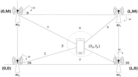
Figure 1.
The Angle of Arrival (AoA) scheme.
The receiver first measures the arrival times of the positioning signals. Then, from the differences in the arrival times, the receiver can determine the differences in the azimuths of the BSs. For example, let be the arrival times of the positioning signals and let , and be the differences of the azimuth angles of , and , respectively. Then, the receiver can find , and . Finally, the receiver finds its own position given by and , where
and transmits the position information to the BSs.
2.3. Time of Arrival (ToA)
The ToA scheme is a wireless positioning method that estimates a signal source position from the arrival times of the positioning signal at the receivers. In this case, all the signal sources and receivers should be synchronized [17,18], while the positioning signal should contain a time stamp.
The ToA scheme is illustrated in Figure 2. In a two-dimensional plane, there are three BSs and a single user and the BSs attempt to measure the user position. Meanwhile, the user is at position and the three BSs are at , and , respectively. From the time of arrival (ToA) at the ith BS (denoted by ), the can determine the distance between them, as given by
where c is the speed of light. Then, the position of the user satisfies that
Thus, the BSs can determine the user position because it is at the intersection of the circles centered at each BS with the corresponding radius of . Note that although we explained the ToA scheme in synchronous networks, they are also studied in asynchronous networks [19,20].
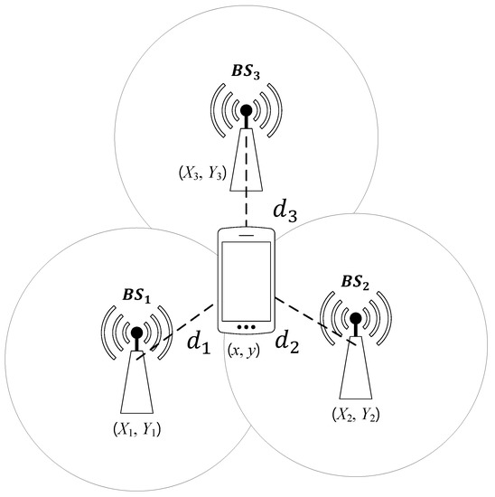
Figure 2.
The Time of Arrival (ToA) scheme.
2.4. Time Difference of Arrival (TDoA)
The TDoA scheme is a positioning scheme that uses the arrival time differences of positioning signal at the receivers [21]. Unlike the ToA scheme, the TDoA scheme only measures the absolute difference between the arrival times, so is easier to implement than the ToA scheme. The TDoA scheme is illustrated in Figure 3.
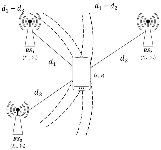
Figure 3.
The Time Difference of Arrival (TDoA) scheme.
There are three BSs of which the positions are , and . We denote by the position of a source node and by the position of the . Then, from the arrival time difference, we can obtain the distance differences, that is, for . Therefore, the position of the signal source can be estimated from the intersection of hyperbolas.
2.5. Fingerprinting
The fingerprinting scheme is the positioning scheme that estimates the user position from a database, which has already been measured [22,23]. The implementation of the fingerprinting scheme is divided into the training phase and the positioning phase. In the training phase, all BSs make a database by collecting the propagation characteristics of received signals (e.g., RSSs) from RF devices at known positions. Then, in the positioning phase, the BSs estimate the position of an RF device by comparing the propagation characteristic of the received signal with the database. The fingerprinting scheme is widely investigated especially for indoor environment, where the signal propagation model based distance estimation is hard. Compared to other positioning schemes, the fingerprinting scheme is more robust, accurate and cost-efficient for indoor positioning [6]. The fingerprinting scheme also has accurate position estimation for multipath issues and NLoS propagation in challenging environment [7]. In recent years, the fingerprinting scheme has also been widely utilized for outdoor positioning due to its accuracy, energy efficiency and low latency. For outdoor positioning, the fingerprinting scheme used, varies with the operating environment and performance. These schemes can be classified as visual fingerprinting, motion fingerprinting, signal fingerprinting and hybrid fingerprinting. Each scheme has pros and cons for different situations [8].
2.6. Hybrid Schemes
As we explained, various parameters such as RSS, AoA and TDoA can be used for positioning and hybrid positioning schemes use more than two parameters for more accurate position information. The TDoA/AoA scheme roughly estimates the distance between BSs and the user with TDoA and then determines a more accurate user’s position with AoA [24]. Also, the ToA/RSS schemes are studied in Reference [25,26,27], and the RSS/AoA scheme was studied in Reference [28]. Hybrid positioning schemes can obtain more accurate position information, so enables to provide a stable location-based service (LBS). However, they are hard to implement and requires more time for estimation.
3. Problem Formulation
In this section, we formulate our problem and propose an efficient location tracking scheme.
3.1. System Model
Our system model is depicted in Figure 4. There are K BSs and a single user in a certain area comprising a safe zone and an unsafe zone. The user is moving around the safe zone and the BSs trace the user position to prevent the user from entering the unsafe zone. To help the BS monitoring, the user periodically broadcasts a positioning signal. Thus, the BSs can determine the user position from the received signal strengths (RSSs). For example, there can be a user swimming on the water with a wireless device in a life jacket. In this case, the BSs need to monitor the user position for safety and the user’s mobile device broadcasts the positioning signal for the BS’s monitoring.
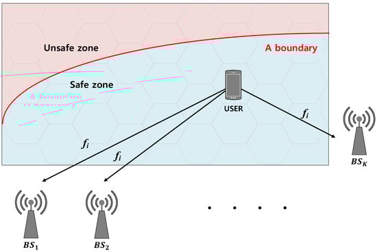
Figure 4.
System model.
In our proposed positioning scheme, the positioning signal frequency changes according to the user position. Our proposed scheme is based on the fingerprinting scheme, which we explained in Section 2. For the fingerprinting scheme, we divided the whole area into N Voronoi regions. Once the BSs locate the cell in which the user belongs (i.e., the user’s Voronoi region) from the RSS, the BSs notify the user of the new positioning signal broadcasting frequency. We denote by the user’s positioning signal frequency when the user is in cell i.
3.2. Risk Modeling
In our system model, the purpose of wireless positioning is to prevent the user from entering the unsafe zone. Thus, the BSs require more accurate information of user position as the user gets closer to the unsafe zone. Obviously, the user’s location accuracy is proportional to the frequency of the user’s positioning signal transmission (i.e., ) because we assumed that both the user speed and the ocean current speed are constants. Moreover, the risk is inversely proportional to the location accuracy. Thus, we have the following relationship:
Next, we propose a risk model and optimize our positioning scheme under this risk model. There are many ways to model the risk of the user. Thus, we designed our risk model to be capable of generalizing many scenarios and assigning the proper factors. However, note that once the risk model is given, our proposed positioning scheme can be readily extended for the risk model.
In our risk model, we consider the following relationship.
Then, we can define the risk at the cell i as a function of signal transmission frequency (i.e., ) as follows:
In (6), is the user positioning signal transmission frequency (i.e., the position information accuracy) at cell i and is a positive constant (i.e., ) that represents the sensitivity of the risk to the accuracy. In this case, is the average water depth at cell i and is the sensitivity of the risk to the water depth. The factor is the weight to reflect the effects of the other factors (e.g., ocean current speed). With the definition of (6), the overall risk function is given by
where N is the total number of cells and is the probability that the user is in the cell i. When the user’s position is uniformly distributed in the safe zone, the probability becomes the ratio of the area of cell i to the area of the safe zone, that is,
3.3. Limited Power Budget
As we consider the mobile user in the marine environment, the user’s battery power budget should also be considered. The user’s positioning signal frequency should be carefully controlled considering the user’s battery power budget. We denote by W the power consumption of the user’s one time transmission of the positioning signal. Then, when the user is in cell i, the user’s power consumption becomes per second. Thus, the user’s average power consumption per second is equal to the sum of the product of the power consumption per second in cell i and the probability of belonging to cell i for all cells is described as follows.
When L is the expected operating time in seconds, the product of the average power consumption per second and the desired operating time should not exceed the total energy of the user, denoted by E, that is,
3.4. Problem Description
In this paper, we find the optimal wireless positioning signal frequency that minimizes the overall risk (i.e., (7)) considering the user’s limited battery power budget (i.e., (11)) as follows:
For notational simplicity, we establish the equivalent problem as follows:
where is a constant related to the risk at the cell i and is a constant related to the power budget.
3.5. Conventional Scheme
The conventional wireless positioning scheme does not change the positioning signal frequency according to the current position. Thus, as a reference scheme, we consider the wireless positioning scheme with the same frequency at all positions, that is,
4. Our Proposed Risk-Aware Wireless Positioning Scheme
In this section, we find the optimal positioning signal frequency at each cell by solving the optimization problem (P1’). We start from the following Lemma.
Lemma 1.
The optimization problem (P1’) is a convex problem.
Proof.
We recall the objective function of the problem (P1) as follows:
Then, is the convex function of because all of , and are positive constants and the term is the convex function of whose second derivative is positive for , that is,
Since the sum of convex functions is also a convex function [29], (13) is a convex function of . Also, the constraint function is convex, so the problem (P1’) is a convex problem. □
To solve the convex problem, we establish the Lagrangian denoted by as follows:
where is the Lagrangian multiplier.
5. Numerical Results
In this section, we evaluate our proposed wireless positioning scheme. We first explain the RSS map and the risk map modeling, by which our proposed localization scheme is evaluated and then compare our proposed scheme with the conventional one. Note that Figure 5 is based on the actual measurement and Figure 6 is based on our modeling for performance evaluation. Also, Figure 7, Figure 8, Figure 9 and Figure 10 are from the simulation.
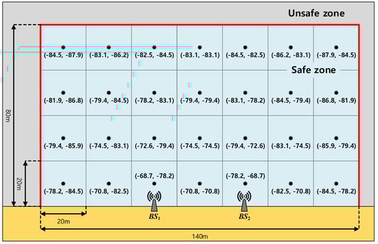
Figure 5.
The Received Signal Strength (RSS) map (dBm).
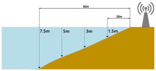
Figure 6.
The water depth modeling for the performance evaluation.
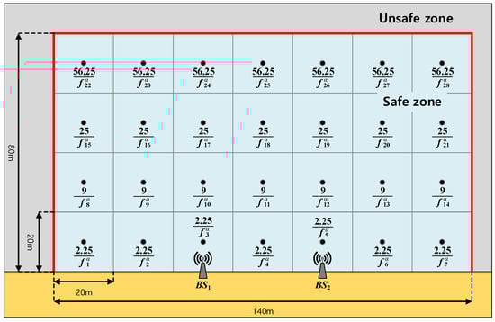
Figure 7.
The risk map that represents given in (6).
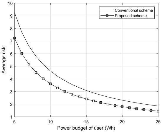
Figure 8.
The average risk with respect to the power budget of the user.
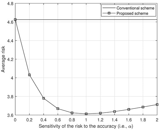
Figure 9.
The average risk with respect to the sensitivity of the risk to the position accuracy (i.e., ).
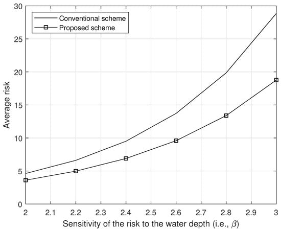
Figure 10.
The average risk with respect to the sensitivity of the risk to the water depth (i.e., ).
Because our proposed localization scheme is based on the fingerprinting scheme, we first model the RSS map. We consider two BSs of the IEEE802.11g (i.e., WiFi) standard, of which the positions are (−20, 0) and (20, 0), respectively, in meters. Then, we obtain the received signal strength (RSS) map by measurement. Figure 5 shows the geometry we considered with the measured RSSs at each cell. As can be seen in Figure 5, we consider a total of 28 cells (i.e., ), where each cell is a square with sides 20 m in length and the measured RSS values from and are marked from the center of each cell.
Because we are considering maritime safety, we need to define the risk with respect to the user’s position. To model the risk at each cell (i.e., given in (6)), we consider the parameter , which means that the risk linearly decreases with respect to the positioning signal frequency. Then, to model the risk from depth, we consider the geometry given in Figure 6 with the parameter , which means that the risk increases with respect to the square of the depth. For other risk factors, we simply consider . As a result, the risk is modeled as in Figure 7.
For other parameters, we assume that the power consumption for a single time positioning signal transmission is 1 watt (i.e., W). In Figure 8, we plot the achievable average risk of a user with respect to the user’s battery power budget (i.e., E), when the user device lifetime is two hours (i.e., s). As can be observed in Figure 8, the user’s average risk decreases as the user’s battery budget increases both in our proposed scheme and in the conventional scheme. This is because with greater battery power budget, the user can more frequently transmit the positioning signal during the device lifetime. However, with the same power budget, we observed that our proposed scheme decreases average risk by adaptively transmitting the positioning signal according to the position.
Figure 9 shows the average risk with respect to the different sensitivities of the risk to the accuracy (i.e., ), where Wh, and all other parameters are same. In Figure 9, we can observe that our proposed scheme outperforms to the conventional scheme for any value of . Also, in Figure 10, we show the average risk per different sensitivities of the risk to the water depth (i.e., ), where Wh, and all other parameters are same. As we can see in Figure 10, our proposed scheme outperforms to the conventional scheme for any value of .
6. Conclusions
In this paper, we proposed a safety-aware positioning scheme based on the fingerprinting scheme, which efficiently decreases the average risk in the maritime environment. We defined a risk function, which is influenced by various factors such as location accuracy, depth, ocean current speed and geometry. Then, we found the optimal positioning signal transmission frequency that minimizes the user’s average risk. The numerical result shows that our proposed positioning scheme decreases the average risk, compared to the conventional one, assuming a user with the same battery power budget.
Author Contributions
Conceptualization, K.Y.S. and J.H.L.; methodology, K.Y.S. and J.H.L.; software, K.Y.S.; validation, K.Y.S., J.Y.R. and J.H.L.; formal analysis, K.Y.S., J.Y.R. and J.H.L.; investigation, K.Y.S. and J.H.L.; resources, K.Y.S., J.Y.R. and J.H.L.; data curation, K.Y.S.; writing—original draft preparation, K.Y.S.; writing—review and editing, J.Y.R. and J.H.L.; visualization, K.Y.S.; supervision, J.Y.R. and J.H.L.; project administration, J.Y.R. and J.H.L.; funding acquisition, J.Y.R. and J.H.L.
Funding
This work was funded by Hankuk University of Foreign Studies Research Fund of 2018 and by the National Research Foundation of Korea(NRF) grant funded by the Korea government(MSIT) (No. NRF-2016R1C1B2010281). This work was also funded by the National Research Foundation of Korea (NRF) grant funded by the Korea government (MSIP; Ministry of Science, ICT & Future Planning) (No. 2018-0229).
Acknowledgments
This work was supported by Hankuk University of Foreign Studies Research Fund of 2018 and by the National Research Foundation of Korea(NRF) grant funded by the Korea government(MSIT) (No. NRF-2016R1C1B2010281). This work was also supported by the National Research Foundation of Korea (NRF) grant funded by the Korea government (MSIP; Ministry of Science, ICT & Future Planning) (No. 2018-0229).
Conflicts of Interest
The authors declare no conflict of interest.
Abbreviations
The following abbreviations are used in this manuscript:
| LBS | Location-based service |
| GPS | Global positioning system |
| LoS | Line-of-sight |
| RF | Radio frequency |
| AoA | Angle of arrival |
| ToA | Time of arrival |
| TDoA | Time difference of arrival |
| NLoS | Non-line-of-sight |
| BS | Base station |
| RSS | Received signal strength |
References
- Perusco, L.; Michael, K. Control trust privacy and security: Evaluating location-based services. IEEE Technol. Soc. Mag. 2007, 26, 4–16. [Google Scholar] [CrossRef]
- Ferreira, A.F.G.; Fernandes, D.M.A.; Catarino, A.P.; Monteiro, J.L. Localization and positioning systems for emergency responders: A survey. IEEE Commun. Surv. Tuts. 2017, 19, 2836–2870. [Google Scholar] [CrossRef]
- Drawil, N.M.; Amar, H.M.; Basir, O.A. GPS localization accuracy classification: A context-based approach. IEEE Trans. Intell. Transp. Syst. 2013, 14, 262–273. [Google Scholar] [CrossRef]
- Fallahi, K.; Cheng, C.; Fattouche, M. Robust positioning systems in the presence of outliers under weak GPS signal conditions. IEEE Syst. J. 2012, 6, 401–413. [Google Scholar] [CrossRef]
- Tahat, A.; Kaddoum, G.; Youse, S.; Valaee, S.; Gagnon, F. A look at the recent wireless positioning techniques with a focus on algorithms for moving receivers. IEEE Access 2016, 4, 6652–6680. [Google Scholar] [CrossRef]
- Luo, Y.; Hoeber, O.; Chen, Y. Enhancing Wi-Fi fingerprinting for indoor positioning using human-centric collaborative feedback. Hum. Centric Comput. Inf. Sci. 2013, 3, 2. [Google Scholar] [CrossRef]
- Takenga, C.; Kyamakya, K. A low-cost fingerprint positioning system in cellular networks. In Proceedings of the Second International Conference on Communications and Networking in China, Shanghai, China, 22–24 August 2007; pp. 915–920. [Google Scholar]
- Vo, Q.D.; De, P. A survey of fingerprint-based outdoor localization. IEEE Commun. Surv. Tut. 2015, 18, 491–506. [Google Scholar] [CrossRef]
- Dardari, D.; Conti, A.; Ferner, U.; Giorgetti, A.; Win, M.Z. Ranging with ultrawide bandwidth signals in multipath environments. Proc. IEEE 2009, 97, 404–426. [Google Scholar] [CrossRef]
- Shen, Y.; Win, M.Z. Fundamental limits of wideband localization—Part I: A general framework. IEEE Trans. Inf. Theory 2010, 56, 4956–4980. [Google Scholar] [CrossRef]
- Shen, Y.; Wymeersch, H.; Win, M.Z. Fundamental limits of wideband localization—Part II: Cooperative networks. IEEE Trans. Inf. Theory 2010, 56, 4981–5000. [Google Scholar] [CrossRef]
- Coluccia, A. Reduced-bias ML-based estimators with low complexity for self-calibrating RSS ranging. IEEE Trans. Wirel. Commun. 2013, 12, 1220–1230. [Google Scholar] [CrossRef]
- Fascista, A.; Ciccarese, G.; Coluccia, A.; Ricci, G. Angle of arrival-based cooperative positioning for smart vehicles. IEEE Trans. Intell. Transp. Syst. 2018, 19, 2880–2892. [Google Scholar] [CrossRef]
- Guerra, A.; Guidi, F.; Dardari, D. Single-anchor localization and orientation performance limits using massive arrays: MIMOvs.beamforming. IEEE Trans. Wirel. Commun. 2018, 17, 5241–5255. [Google Scholar] [CrossRef]
- Shen, Y.; Win, M.Z. On the accuracy of localization systems using wideband antenna arrays. IEEE Trans. Commun. 2010, 58, 270–280. [Google Scholar] [CrossRef]
- Baik, K.J.; Lee, S.J.; Jang, B.J. AoA-based local positioning system using a time-modulated array. J. Electromagn. Eng. Sci. 2017, 17, 181–185. [Google Scholar] [CrossRef]
- Go, S.R. Effective ToA-based indoor localization method considering accuracy in wireless sensor networks. J. Korean Inst. Commun. Inf. Sci. 2016, 41, 640–651. [Google Scholar]
- Go, S.R. An effective ToA-based localization method with adaptive bias computation. J. Korean Inst. Electr. Electron. Mater. Eng. 2016, 20, 1–8. [Google Scholar] [CrossRef][Green Version]
- Vaghefi, R.M.; Buehrer, R.M. Cooperative joint synchronization and localization in wireless sensor networks. IEEE Trans. Signal Process. 2015, 63, 3615–3627. [Google Scholar] [CrossRef]
- Ricciato, F.; Sciancalepore, S.; Gringoli, F.; Facchi, N.; Boggia, G. Position and velocity estimation of a non-cooperative source from asynchronous packet arrival time measurements. IEEE Trans. Mob. Comput. 2018, 17, 2166–2179. [Google Scholar] [CrossRef]
- Choi, D.H.; Go, Y.J.; Lee, J.H.; Na, T.H.; Choi, J.S. Study of effectiveness of atmospheric environment on TDoA position estimation. In Proceedings of the Korean Society for Noise and Vibration Engineering Conference, Pyeongchang, Korea, 28–30 October 2015; pp. 150–154. [Google Scholar]
- An, T.K.; Ahn, C.H.; Nam, M.W.; Park, J.H.; Lee, Y.S. A study on improving accuracy of subway location tracking using WiFi fingerprinting. J. Korea Acad. Ind. Coop. Soc. 2016, 17, 1–8. [Google Scholar] [CrossRef]
- He, S.; Chan, S.H.G. Wi-Fi fingerprint-based indoor positioning: Recent advances and comparisons. IEEE Commun. Surv. Tutor. 2016, 18, 466–490. [Google Scholar] [CrossRef]
- Cong, L.; Zhuang, W. Hybrid TDOA/AOA mobile user location for wideband CDMA cellular systems. IEEE Trans. Wirel. Commun. 2002, 1, 439–447. [Google Scholar] [CrossRef]
- Catovic, A.; Sahinoglu, Z. The cramer-rao bounds of hybrid TOA/RSS and TDOA/RSS location estimation schemes. IEEE Commun. Lett. 2004, 8, 626–628. [Google Scholar] [CrossRef]
- Laaraiedh, M.; Yu, L.; Avrillon, S.; Uguen, B. Comparison of hybrid localization schemes using RSSI, TOA, and TDOA. In Proceedings of the 17th European Wireless 2011—Sustainable Wireless Technologies, Vienna, Austria, 27–29 April 2011; pp. 1–5. [Google Scholar]
- Coluccia, A.; Fascista, A. On the hybrid TOA/RSS range estimation in wireless sensor networks. IEEE Trans. Wirel. Commun. 2018, 17, 361–371. [Google Scholar] [CrossRef]
- Tomic, S.; Beko, M.; Dinis, R.; Montezuma, P. A closed-form solution for RSS/AoA target localization by spherical coordinates conversion. IEEE Wirel. Commun. Lett. 2016, 5, 680–683. [Google Scholar] [CrossRef]
- Boyd, S.; Vandenberghe, L. Convex Optimization; Cambridge Univ. Press: Cambridge, UK, 2004. [Google Scholar]


© 2019 by the authors. Licensee MDPI, Basel, Switzerland. This article is an open access article distributed under the terms and conditions of the Creative Commons Attribution (CC BY) license (http://creativecommons.org/licenses/by/4.0/).