Development of Automatic Accumulating Equipment for Roller-Type Onion Pot-Seeding Machine


Abstract
:1. Introduction
2. Materials and Methods
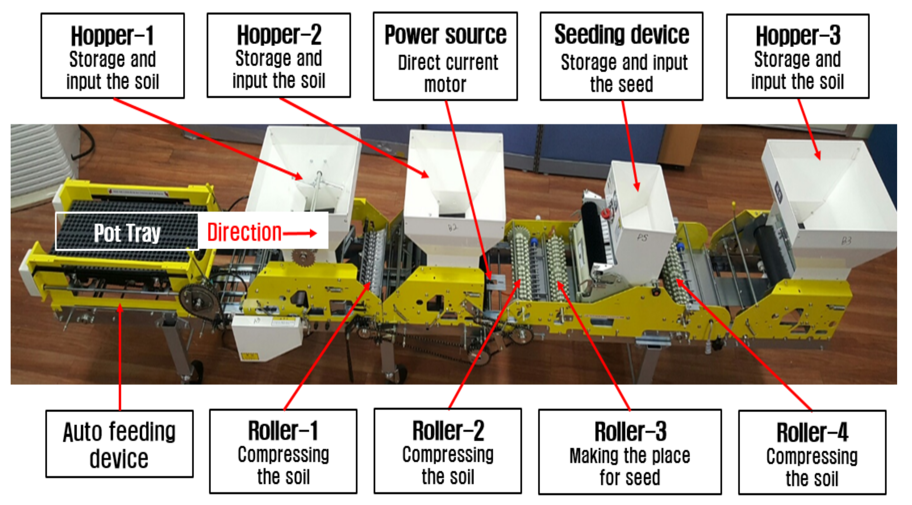
2.1. Structure of Existing Roller-Type Onion Pot-Seeding Machine [10]
2.2. Requirements for Accumulating Equipment
- Manipulation must be simple for the convenience of the worker.
- The system must be constructed so that the impact occurring in the accumulating process can be minimized and pot trays can be accumulated in a safe manner.
- The equipment must be easily attached to and detached from the existing roller-type pot-seeding machine in order to increase its usefulness.
- If pot trays are over accumulated, their weight may result in excessive pressure on the bottom pot tray. Therefore, workers must be informed regarding the accumulating degree in order to prevent excessive accumulating.
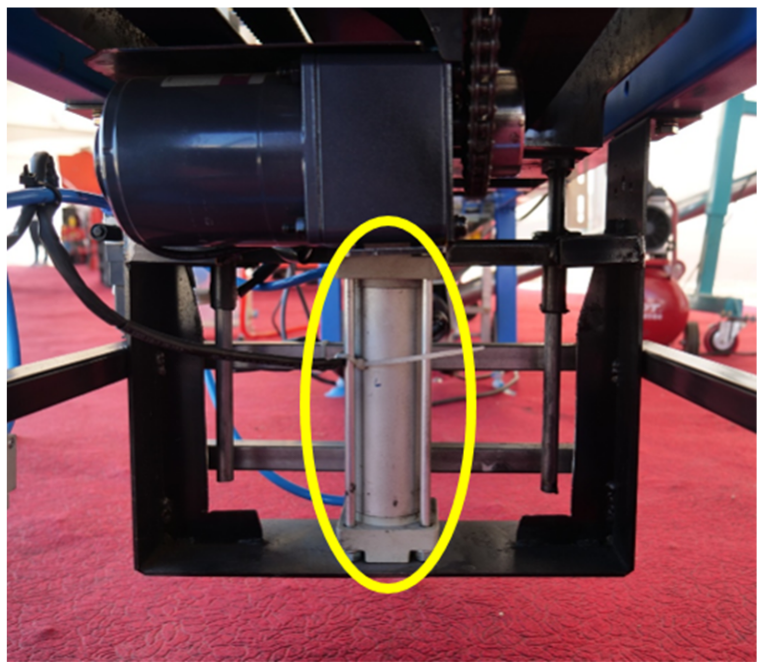
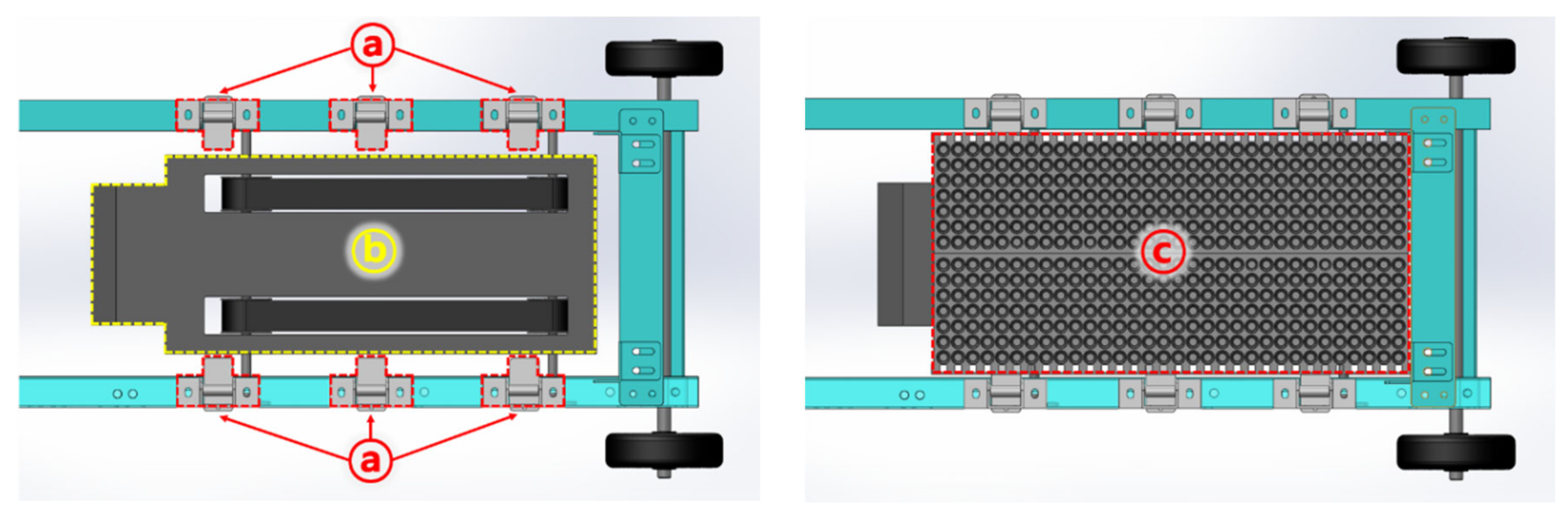
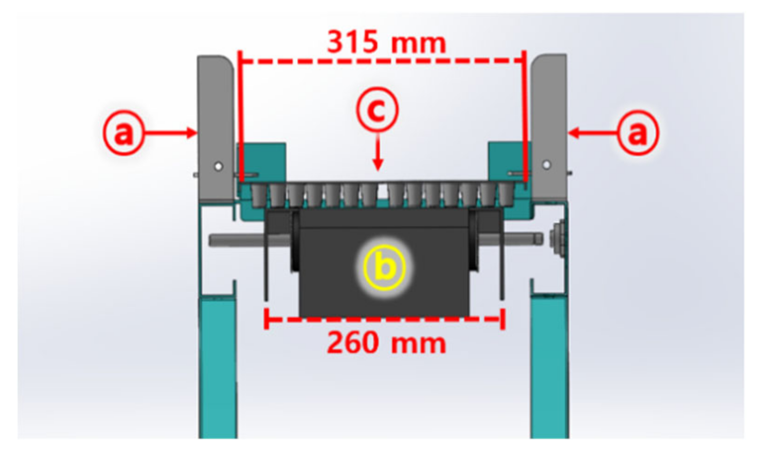
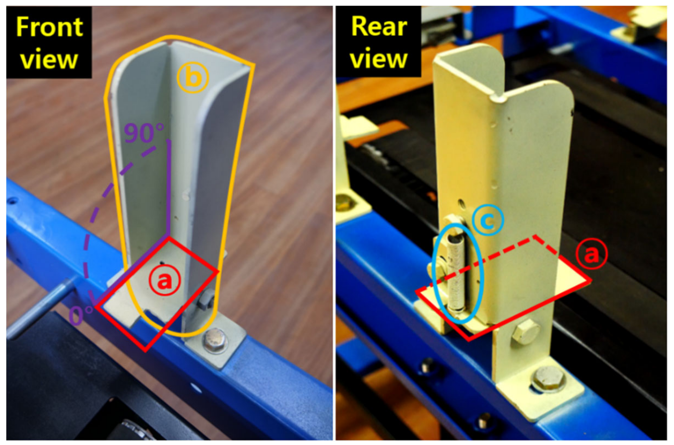
2.3. Details of Developed Accumulating Equipment
2.4. Factorial Experiment to Derive Appropriate Operating Conditions
3. Results and Discussion
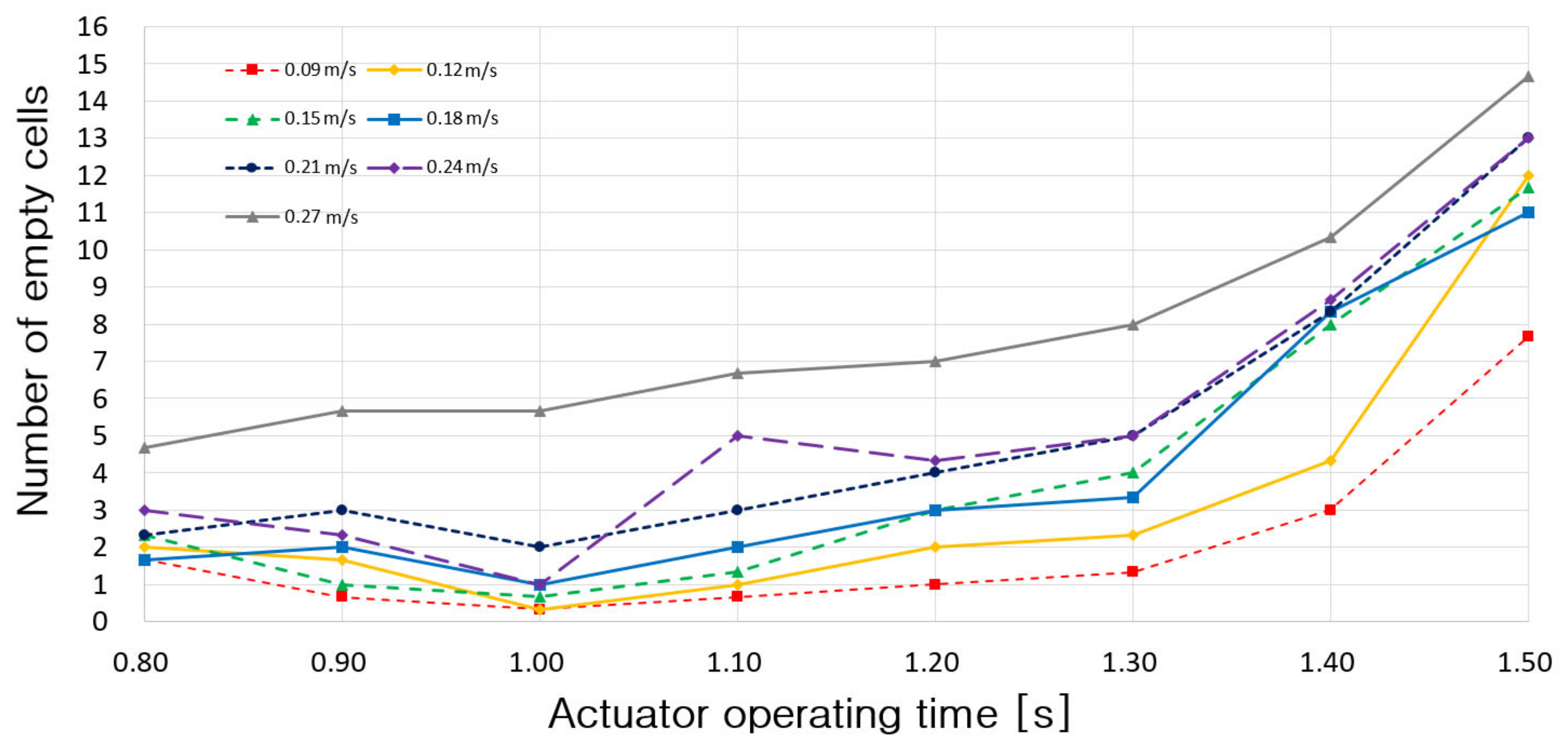
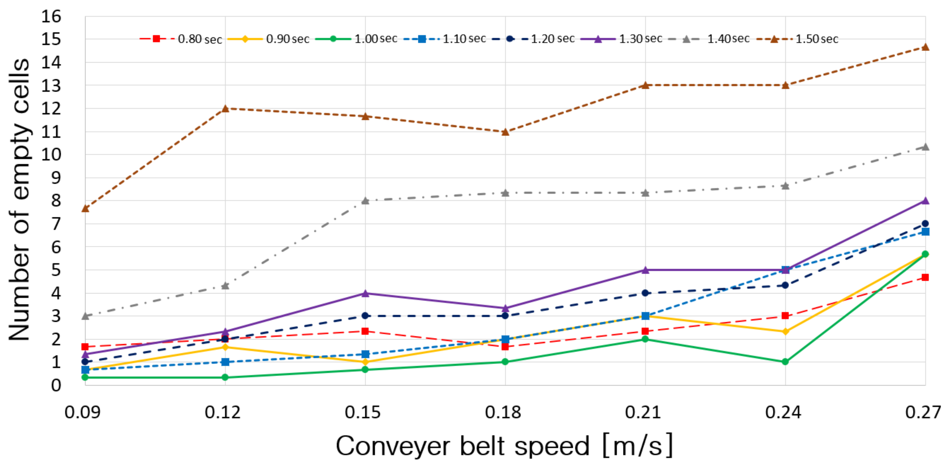
3.1. Results of Factorial Experiment
3.2. Derivation of Appropriate Operating Conditions
4. Conclusions
Author Contributions
Funding
Conflicts of Interest
References
- Chae, H.S.; Kim, K.W.; Lee, K.S.; Kim, S.H.; Lee, K.M.; Choi, Y.W.; Park, K.S. The study on the moving rail-chair and electromotive scissors for preventing of the musculoskeletal disorders. J. Ergon. Soc. Korea 2010, 29, 139–144. [Google Scholar]
- Chae, H.S.; Kim, S.C.; Kim, K.W.; Lee, K.S.; Kim, H.C.; Park, K.S. Prevention of work-related musculoskeletal disorders in grapes pinching by using electro-motion scissors designed ergonomically. J. Ergon. Soc. Korea 2011, 30, 749–755. [Google Scholar] [CrossRef]
- Lee, E.J.; Suh, J.K. Effect of watering control on growth and bulb size of plug seedling in onion (Allium cepa L.) set production. Korean J. Hortic. Sci. Technol. 2007, 27, 167–173. [Google Scholar]
- Hwang, S.J.; Kim, D.H.; Nam, J.S. Design improvement research of onion port-seeding machine for increasing mechanization ratio. Conf. Korean Soc. Agric. Mach. 2016, 21, 93. [Google Scholar]
- Kang, J.H.; Hong, D.P. The package loading equipment development cutting both ends in the process of packaging lumber for improving the working environments. J. Soc. Korea Ind. Syst. Eng. 2008, 29, 135–142. [Google Scholar]
- Chang, Y.C.; Cho, S.I.; Yeo, W.Y. Development of a cabbage loader. Agric. Biosyst. Eng. 2002, 3, 73–78. [Google Scholar]
- Park, K.H.; Park, H.T.; Hye, S.H.; Lee, D.P. A Study on the Current State and Development Strategies of Raising Seedlings Industry; KREI: Seoul, Korea, 2011. [Google Scholar]
- Hwang, S.J. A Study on the Roller-Type Shape, Irrigation and Loading System of Roller-Type Pot-Seeding Machine. Master’s Thesis, Kangwon National University, Chuncheon, Korea, 2019; pp. 42–43. [Google Scholar]
- MAFRA. Development of High Efficiency Transplanting System for Labor-saving of Onion Production; Gyeongsangnam-do Agricultural Research & Extension Services: Jinju, Korea, 2015; pp. 158–160. [Google Scholar]
- Hwang, S.J.; Kang, H.S.; Oh, A.Y.; Nam, J.S. Operational characteristic analysis of roller-type pot-seeding machine for onion. J. Inst. Agric. Anim. Sci. 2017, 51, 145–158. [Google Scholar] [CrossRef]
- Jukam Field Machine Catalog. Available online: http://mnc.jukam.co.kr/theme/basic/catalogue/catalogue3.pdf/ (accessed on 11 May 2019).
- Hwang, S.J.; Park, J.H.; Lee, J.Y.; Nam, J.S. Development of automatic pot tray loading equipment for roller-type pot-seeding machine. Conf. Korean Soc. Agric. Mach. 2018, 23, 85. [Google Scholar]


| Classification | Contents |
|---|---|
| Length Width Height | 3477 mm 510 mm 975 mm |
| Total weight | 165 kg |
| Operation capacity | 360 pot trays/h |
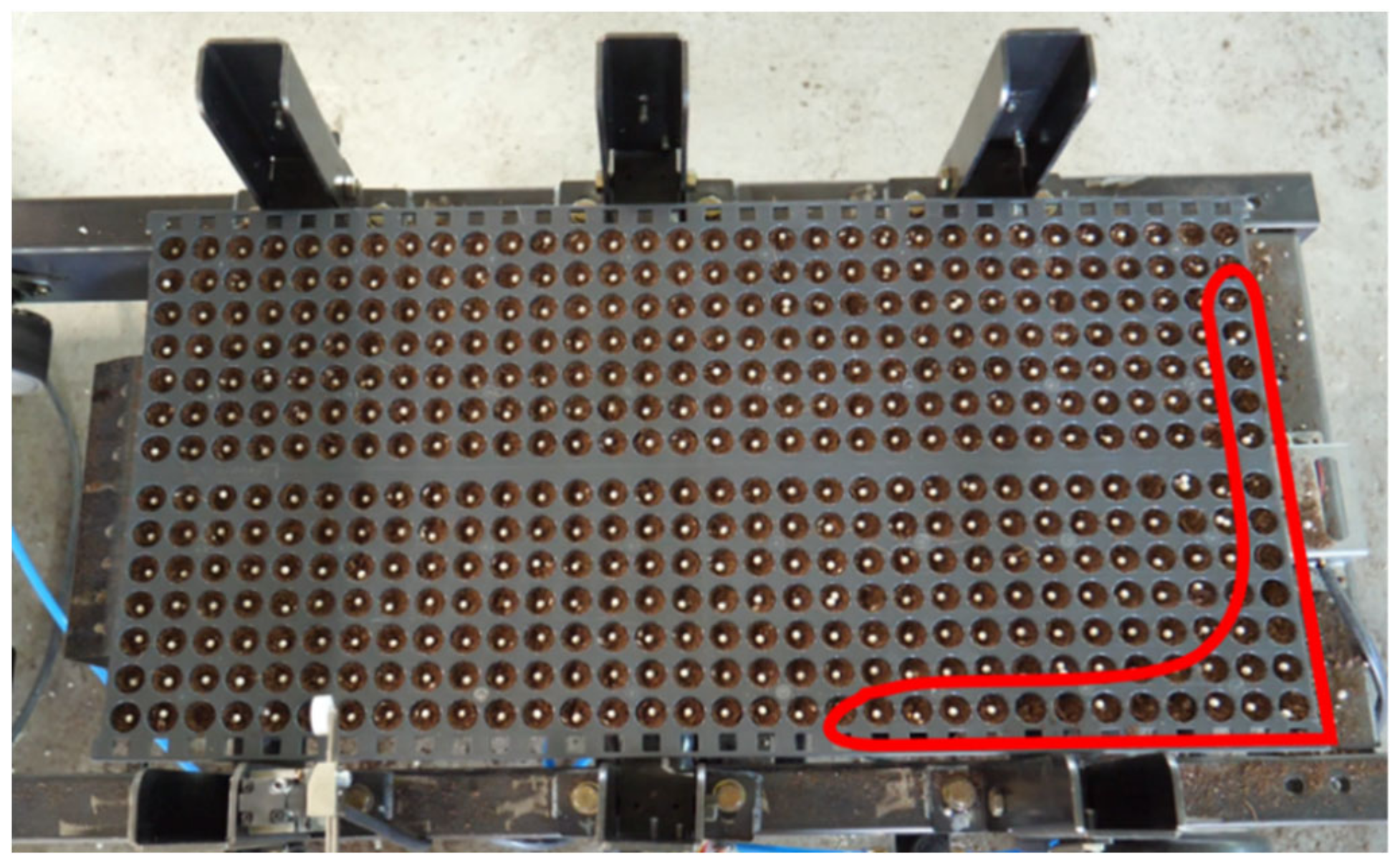
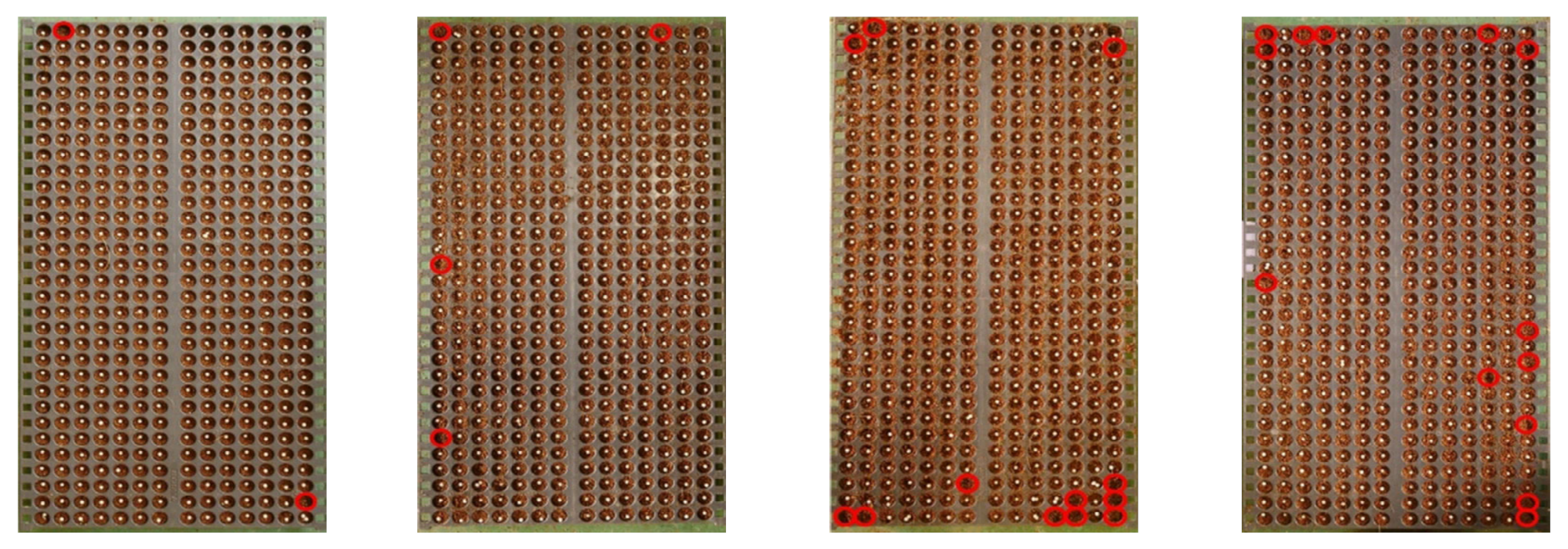
| Number of cells in pot trays | 448 |
| Classification | Contents | |
|---|---|---|
| Model Manufacturer, Nation | TPA2BN50-125 TPC Mechatronics, Republic of Korea | |
| Stroke | 125 mm | |
| Fluid | Pneumatic type | |
| Working pressure | Max | 1.0 MPa |
| Min | 0.05 MPa | |
| Piston velocity | 50–500 mm/s | |
| Source | Sum of Squares | DF | Mean Square | F Value | Pr > F |
|---|---|---|---|---|---|
| Conveyor belt speeds | 486 | 6 | 81 | 144.766 | <0.0001 |
| Actuator operating time | 1745.048 | 7 | 249.2925 | 445.5441 | <0.0001 |
| Conveyor belt speeds actuator operating time | 100.2857 | 42 | 2.387755 | 4.267477 | <0.0001 |
| Conveyor Belt Speed (m/s) | Pneumatic-Type Actuator Operating Times (s) | Average | |||||||
|---|---|---|---|---|---|---|---|---|---|
| 0.8 | 0.9 | 1.0 | 1.1 | 1.2 | 1.3 | 1.4 | 1.5 | ||
| 0.09 | 0.37 | 0.15 | 0.07 | 0.15 | 0.22 | 0.30 | 0.67 | 1.71 | 0.46 |
| 0.12 | 0.45 | 0.37 | 0.07 | 0.22 | 0.45 | 0.52 | 0.97 | 2.68 | 0.72 |
| 0.15 | 0.52 | 0.22 | 0.15 | 0.30 | 0.67 | 0.89 | 1.79 | 2.60 | 0.89 |
| 0.18 | 0.37 | 0.45 | 0.22 | 0.45 | 0.67 | 0.74 | 1.86 | 2.46 | 0.90 |
| 0.21 | 0.52 | 0.67 | 0.45 | 0.67 | 0.89 | 1.12 | 1.86 | 2.90 | 1.13 |
| 0.24 | 0.67 | 0.52 | 0.22 | 1.12 | 0.97 | 1.12 | 1.93 | 2.90 | 1.18 |
| 0.27 | 1.04 | 1.26 | 1.26 | 1.49 | 1.56 | 1.79 | 2.31 | 3.27 | 1.75 |
| Average | 0.56 | 0.52 | 0.35 | 0.63 | 0.78 | 0.92 | 1.63 | 2.65 | |
© 2019 by the authors. Licensee MDPI, Basel, Switzerland. This article is an open access article distributed under the terms and conditions of the Creative Commons Attribution (CC BY) license (http://creativecommons.org/licenses/by/4.0/).
Share and Cite
Hwang, S.-J.; Nam, J.-S. Development of Automatic Accumulating Equipment for Roller-Type Onion Pot-Seeding Machine. Appl. Sci. 2019, 9, 2139. https://doi.org/10.3390/app9102139
Hwang S-J, Nam J-S. Development of Automatic Accumulating Equipment for Roller-Type Onion Pot-Seeding Machine. Applied Sciences. 2019; 9(10):2139. https://doi.org/10.3390/app9102139
Chicago/Turabian StyleHwang, Seok-Joon, and Ju-Seok Nam. 2019. "Development of Automatic Accumulating Equipment for Roller-Type Onion Pot-Seeding Machine" Applied Sciences 9, no. 10: 2139. https://doi.org/10.3390/app9102139