Abstract
In this study, an automatic accumulating equipment for a roller-type onion pot-seeding machine was developed. The developed accumulating equipment accumulates the pot trays that complete the seeding in multiple stages using a conveyor belt and elevator plate, and can be easily attached to the existing roller-type onion pot-seeding machines as it is fabricated as a module. The components were selected to meet the conditions required for the accumulating equipment. A factorial experiment was performed by setting the transport speed of the conveyor belt and the one-time operating time of the actuator as test factors. Through the experiment, appropriate operating conditions to minimize the seed bounce rate in the accumulating process were derived. If the developed accumulating equipment is applied to a roller-type onion pot-seeding machine, the labor force and labor load required for seeding will be reduced.
1. Introduction
A need for ergonomic design is emerging to prevent occupational musculoskeletal diseases that occur owing to the uncomfortable working postures and repeated motions of workers [1,2]. In particular, agricultural works are often performed in harsh conditions such as high temperatures and dusty environment. Thus, studies to reduce the labor load and increase work efficiency of the workers are required [3].
In the case of the roller-type pot-seeding machine used for onion seeding, the work efficiency is high, and the economic efficiency and durability are excellent [4]. However, pot trays that complete the seeding process must be carried one at a time by workers as there is no pot tray accumulating equipment. The labor load of the workers is very high because they have to repeat the uncomfortable posture of bending their backs to pick the pot trays until the end of the seeding work. Therefore, the development of an equipment to accumulate the seeded pot trays in multiple stages and carry them at once is required.
Kang et al. [5] developed accumulating equipment for wood to reduce the labor intensity and to shorten the time required in the wood packaging process. Chang et al. [6] developed a high-efficiency accumulator suitable for cabbage-accumulating work through a mechanical and kinematic analysis. Park et al. [7] developed equipment capable of accumulating up to three pot trays for the automation of the seedling raising process in plant factories. The accumulating equipment used in the seedling raising area can be classified into the round bar type, angle beam type, and flat plate type depending on the element that lifts the pot trays. The round bar type and angle beam type have high power transmission efficiency and relatively low production cost because they use simple mechanical components such as chains and gears. These types, however, cannot be used when the flexibility of the pot trays is high because the contact area between the lift element and pot tray is narrow. For the flat plate type, the production cost is high and the structure is complicated because hydraulic devices such as actuators are used. However, it is not significantly affected by the flexibility of the pot trays because the contact area between the lift element and pot trays is wide [8]. As the pot trays used for onion seeding can be easily bent owing to their high flexibility, the flat plate-type accumulating equipment is required to reduce the bending of the pot trays, thereby minimizing the seed bounce in the accumulating process [9].
In this study, flat plate-type accumulating equipment for a roller-type onion pot-seeding machine was developed, and appropriate operating conditions to minimize the seed bounce in the accumulating process were derived.
2. Materials and Methods
2.1. Structure of Existing Roller-Type Onion Pot-Seeding Machine [10]
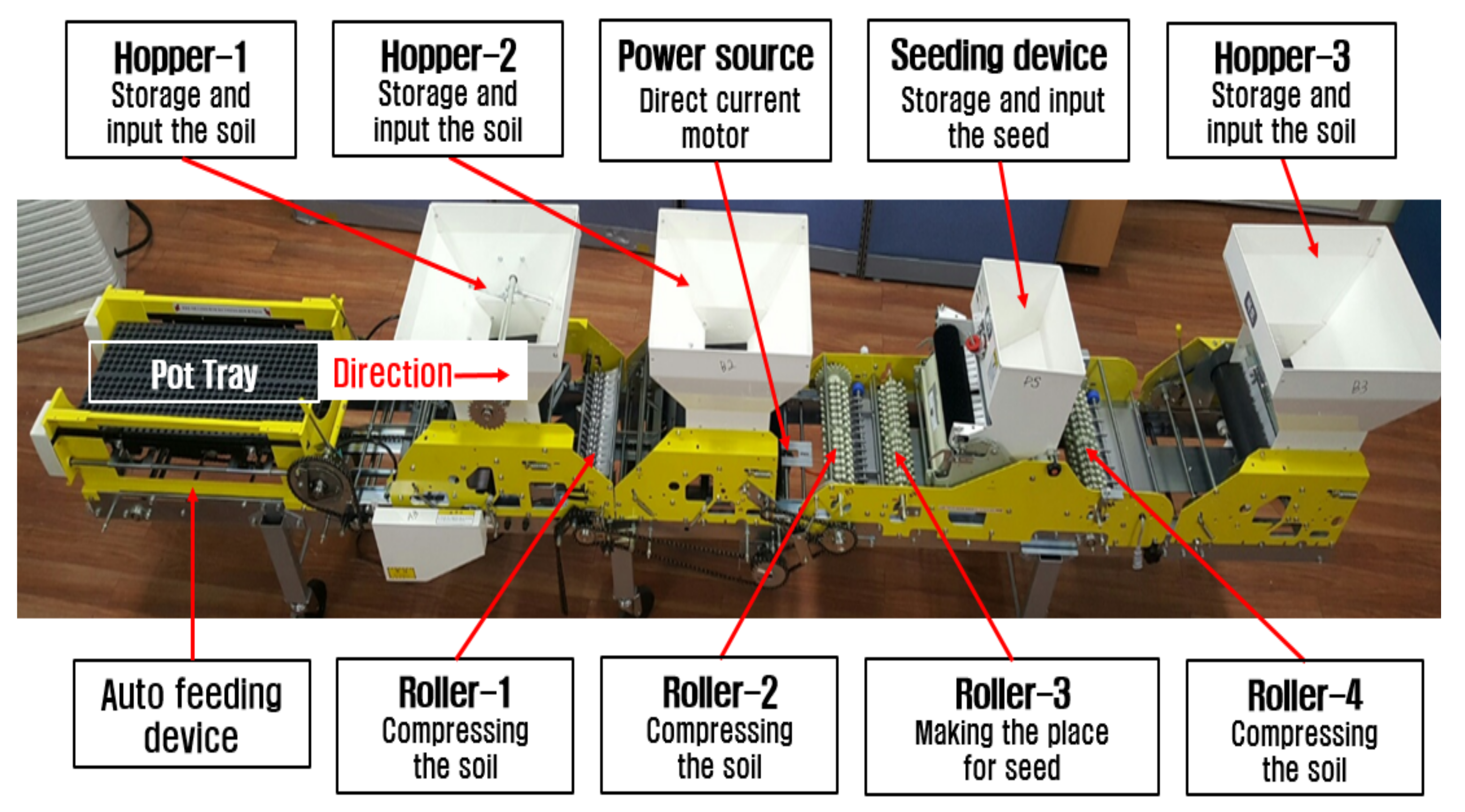
A roller-type onion pot-seeding machine consists of an autofeeding device, hoppers, rollers, a seeding device, and a power source. Their major specifications and shapes are shown in Table 1 and Figure 1. As for the operation of the machine, pot trays are supplied and transported in constant speed by the autofeeding device. Seeding work is performed in pot trays by the following operation: bed soil input by hoppers 1 and 2, bed soil compression by the rollers 1, 2, and 3, seeding by the seeding device, and covering soil input by hopper 3. For the roller-type onion pot-seeding machine, work is completed with two bed soil inputs, one seeding, and one covering soil input, and there is no separate accumulating equipment.

Table 1.
Specifications of existing roller-type onion pot-seeding machine [11].
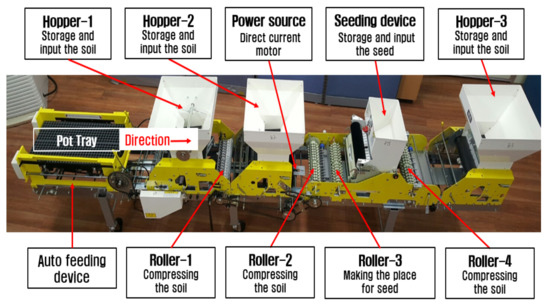
Figure 1.
Picture of existing roller-type onion pot-seeding machine.
2.2. Requirements for Accumulating Equipment
Based on the purpose of the accumulating equipment, components must be selected by considering the following.
- Manipulation must be simple for the convenience of the worker.
- The system must be constructed so that the impact occurring in the accumulating process can be minimized and pot trays can be accumulated in a safe manner.
- The equipment must be easily attached to and detached from the existing roller-type pot-seeding machine in order to increase its usefulness.
- If pot trays are over accumulated, their weight may result in excessive pressure on the bottom pot tray. Therefore, workers must be informed regarding the accumulating degree in order to prevent excessive accumulating.
2.3. Details of Developed Accumulating Equipment
The main components of the accumulating equipment are the conveyor belt, elevator plate, limit switch, pneumatic-type actuator, stopper bracket, alarm bell, control box, and connecting bracket. Their characteristics and functions are as follows:
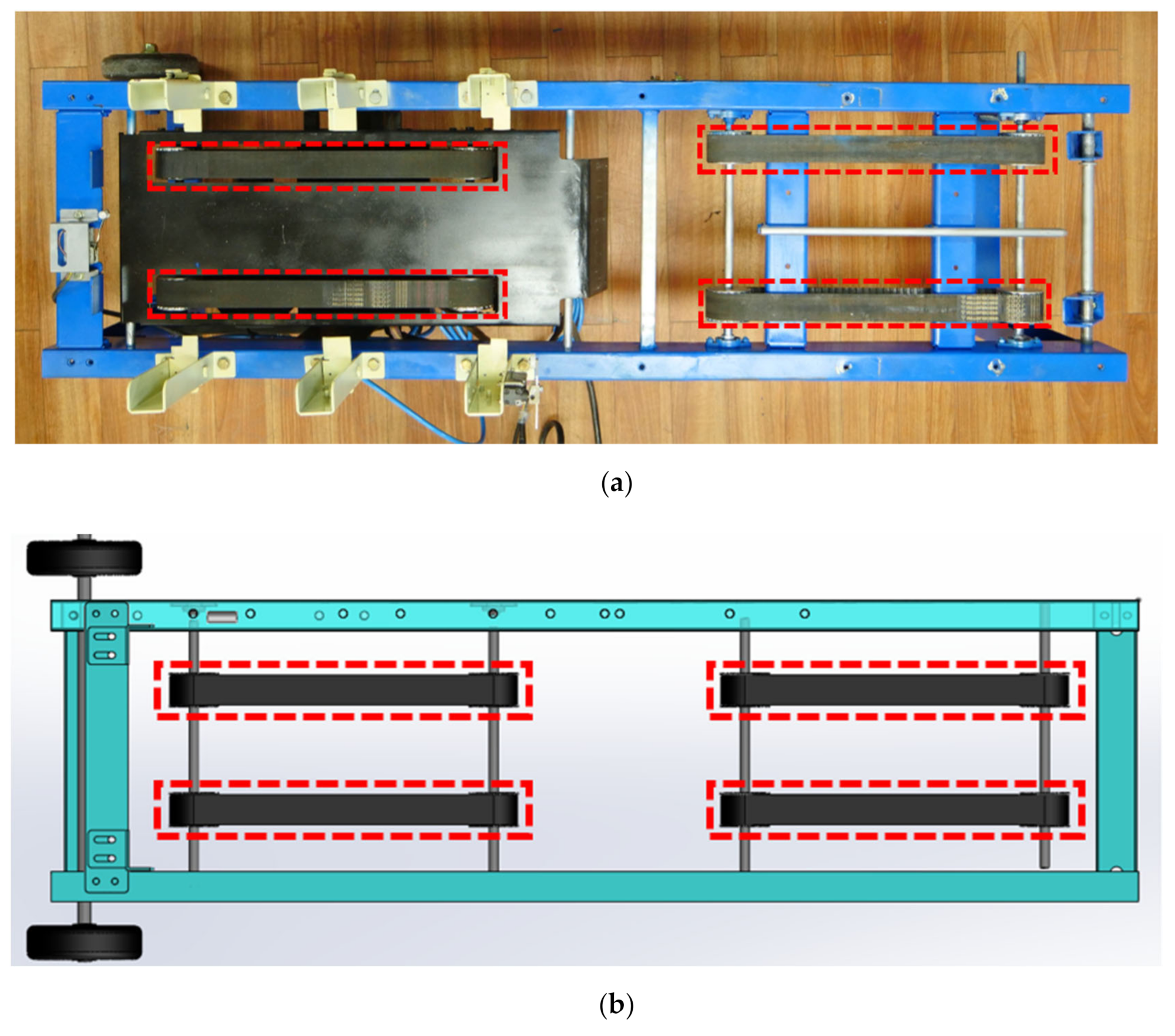
A. Conveyor belt: This transports the pot trays, which pass through hopper 3 of the existing pot-seeding machine, and complete the seeding work, to the accumulating plate (Figure 2). The conveyor belt operates using a motor installed in the lower portion of the supporting frame as a power source. It can adjust the transport speed from 0.03 to 0.3 m/s using the speed controller. The speed controller has 10 stages, and the speed of the first stage is 0.03 m/s. The speed increment for one stage is 0.03 m/s. To transfer the pot trays to the elevator plate, two pairs of conveyor belts are installed with a spacing of approximately 285 mm.

Figure 2.
Shape of conveyor belt: (a) picture and (b) 3D model.
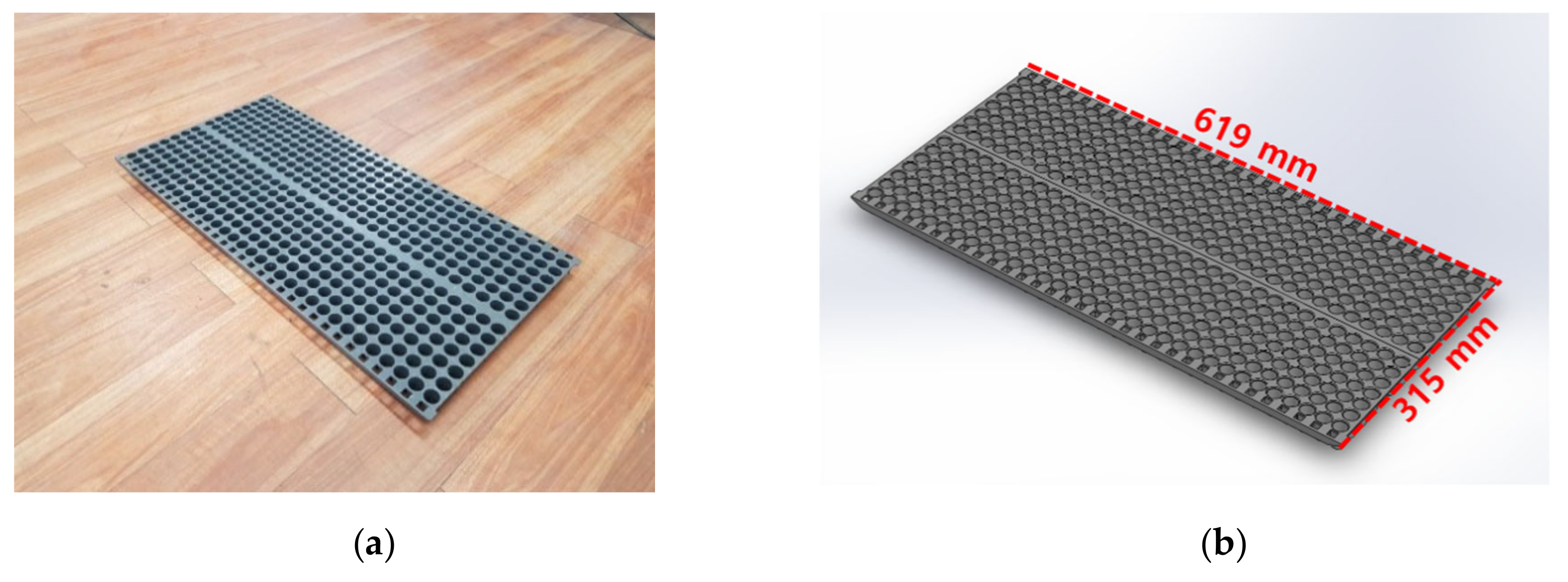
B. Elevator plate: This lifts and accumulates the pot trays transported by the conveyor belt. It moves up and down by a pneumatic-type actuator with air compressor. The area of the elevator plate was designed to be almost identical to the area of a pot tray so that it could support in a stable manner any pot trays that are easily bent owing to high flexibility (Figure 3 and Figure 4).
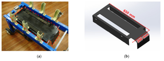
Figure 3.
Shape of elevator plate: (a) picture and (b) 3D model.

Figure 4.
Shape of pot tray: (a) picture and (b) 3D model.
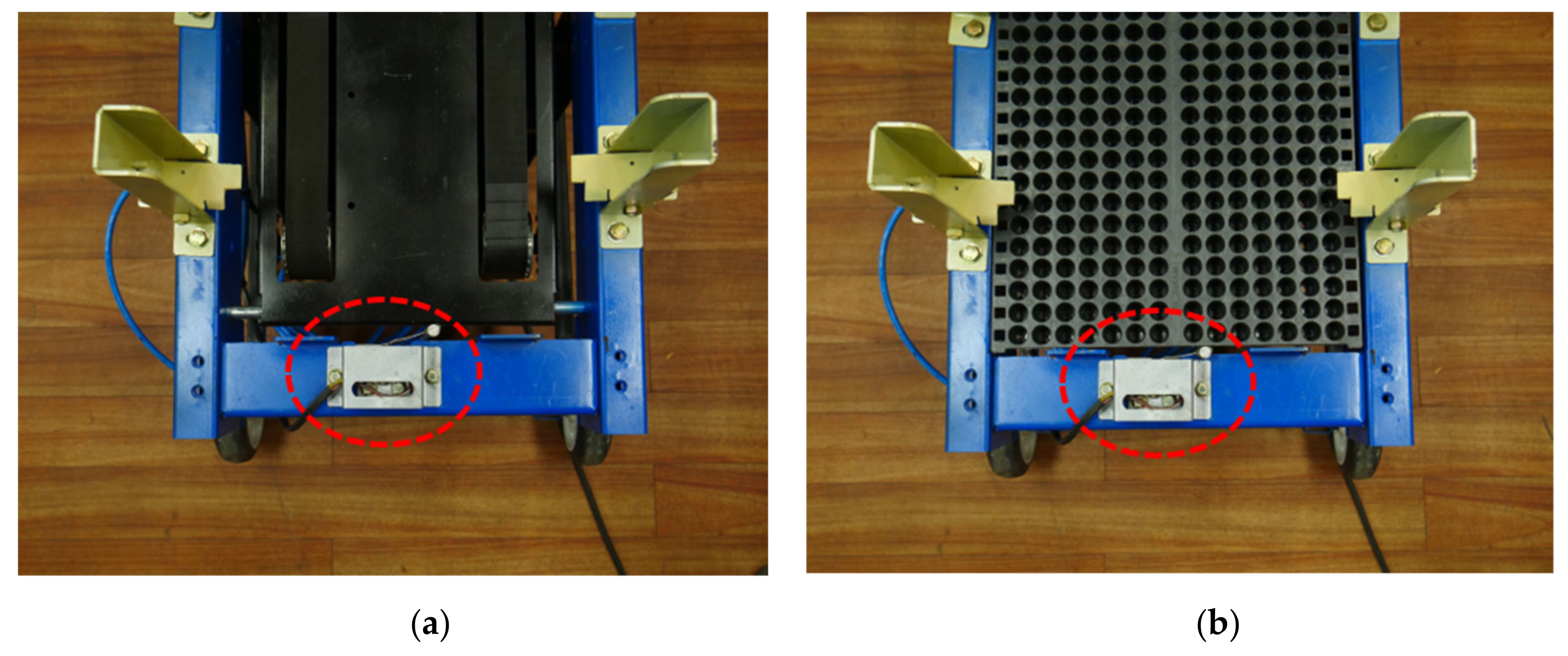
C. Limit switch: When pressed owing to a contact situation, the limit switch stops the conveyor belt by sending a stop signal to the motor. The limit switch operates the pneumatic-type actuator at the same time by sending a start signal to the air compressor. Located on the supporting frame behind the elevator plate, the limit switch is pressed by the end of a pot (Figure 5).
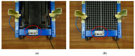
Figure 5.
View of limit switch: (a) noncontact situation and (b) contact situation of limit switch with pot tray.
D. Pneumatic-type actuator: Located at the bottom of the elevator plate, the pneumatic-type actuator performs a stroke movement using the air compressor as a power source. Upon receiving a start signal from the limit switch, the pneumatic-type actuator performs a one-time ascent and descent of the elevator plate with the pot tray through the stroke movement. The stroke time can be adjusted by changing the air supply rate of the air compressor through the timer. The stroke time can be adjusted between 0.1 and 3 s. The shape and specifications of the pneumatic-type actuator are shown in Figure 6 and Table 2, respectively.
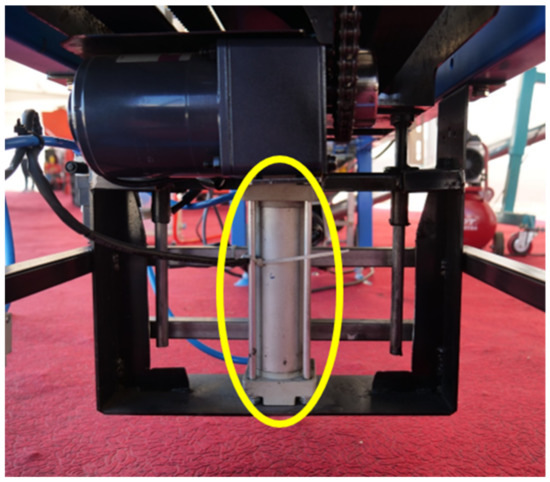
Figure 6.
View of pneumatic-type actuator.
Table 2.
Specifications of pneumatic-type actuator.
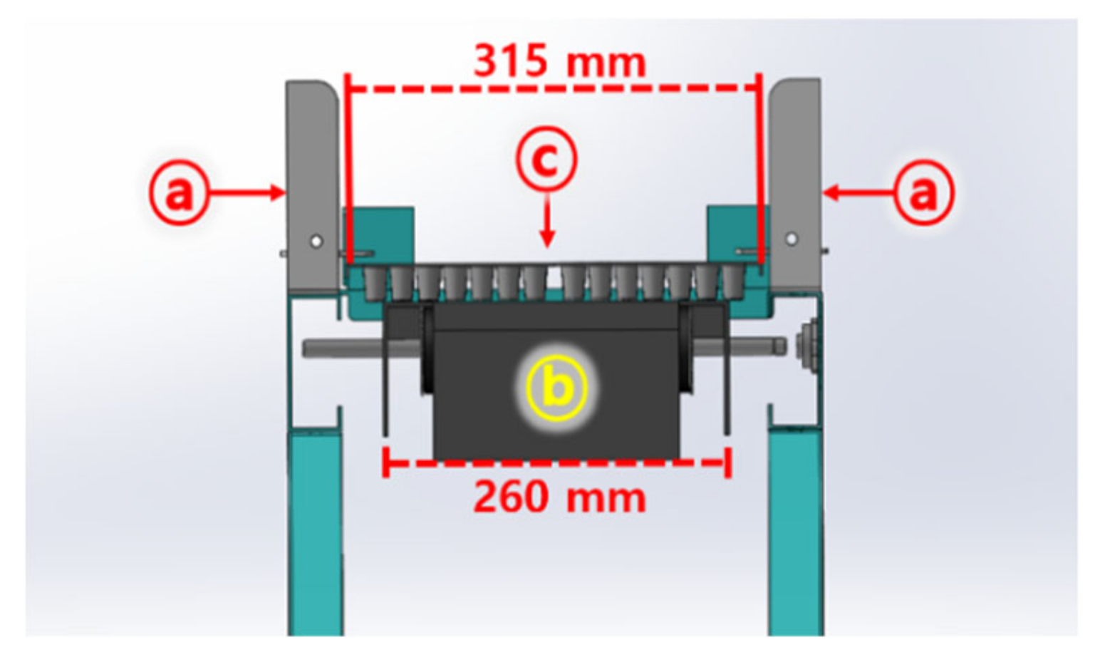
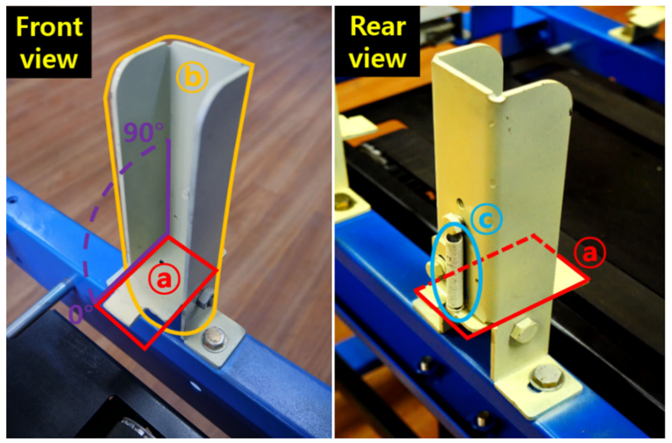
E. Stopper bracket: As a key element in accumulating pot trays, the stopper bracket consists of a bracket, guide, and spring. The bracket enables only an upward tilt by up to 90°, thus it does not block the motion when the elevator plate with a pot tray is raised. After passing of the elevator plate, the bracket returns to the original position by spring force. The side part of the pot tray is placed on the bracket when the elevator plate descends. The side length of the elevator plate is designed to be slightly shorter than that of a pot tray, and thus it does not touch the bracket when it ascends and descends (Figure 7). Therefore, during the one-time ascent–descent motion, the elevator plate returns to the original position, and only the pot tray is supported by the bracket (Figure 8).
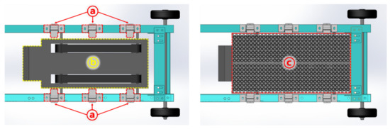
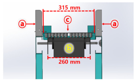
Figure 7.
Lateral size of each component: (a) stopper bracket, (b) elevator plate, and (c) pot tray.

Figure 8.
View of stopper bracket: (a) bracket, (b) guide, and (c) spring.
When the first pot tray is fixed by the stopper bracket, the elevator plate with the second pot tray rises and pushes the first and second pot trays at the same time. When the elevator plate descends, the two pot trays are supported by the stopper bracket. The third and fourth pot trays are accumulated onto the stopper bracket in a similar sequence. In this instance, the first pot tray is located at the top.
A total of six stopper brackets are located on both sides of the elevator plate so that the pot trays can be supported at six points. Through this, bending of the pot trays can be minimized.
F. Alarm bell: When the buzzer is pressed owing to a contact situation, the alarm bell operates to inform the workers for the accumulation situation. Located at the side of the top of the guide, the buzzer is designed to get pressed when an elevator plate with four pot trays ascends. More than five pot trays make it difficult to move at once, and excessive deformations occurred by its self-weight. Therefore, the bell sound reminds the workers that four pot trays have been accumulated (Figure 9). The number of pot trays that operates the bell can be adjusted by changing the height of the alarm bell.
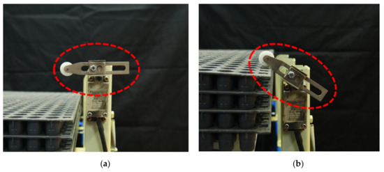
Figure 9.
View of alarm bell: (a) noncontact situation and (b) contact situation of alarm bell with pot tray.
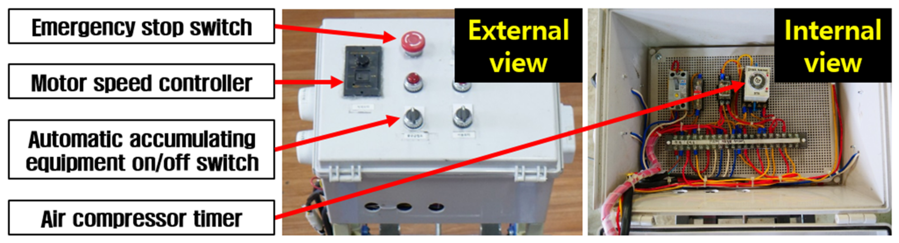
G. Control box: Equipped with a motor speed controller, air compressor timer, accumulating equipment power on/off switch, and emergency stop switch, the control box allows the worker to control the overall operating conditions of the accumulating equipment in one place (Figure 10). The control box was installed on the front of the accumulating equipment considering the workers’ movements, and it was approximately 950 mm above the ground so that workers can operate it without bending significantly at the waist.
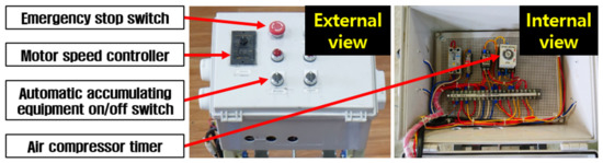
Figure 10.
View of control box.
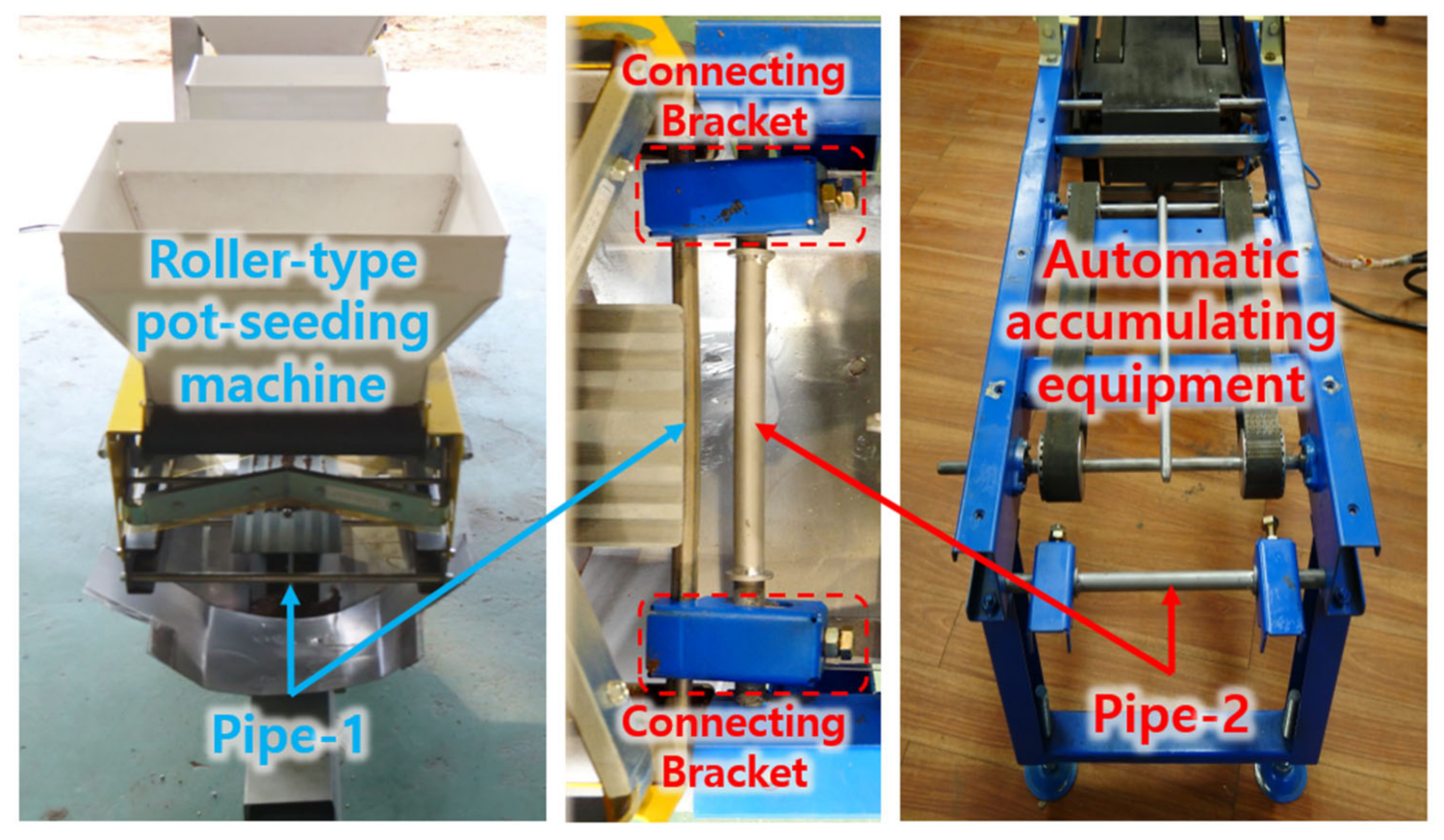
H. Connecting bracket: This is used for connecting the accumulating equipment to a pot-seeding machine. There are two connecting brackets on the steel pipe (pipe 2) located at the front side of accumulating equipment. The hole diameter of connecting bracket was designed to fit with the diameter of steel pipe (pipe 1) located at the end of the roller-type pot-seeding machine. The developed accumulating equipment could be easily attached to and detached from the existing roller-type pot-seeding machine through the fastening of connecting bracket (Figure 11).

Figure 11.
View of connecting bracket.
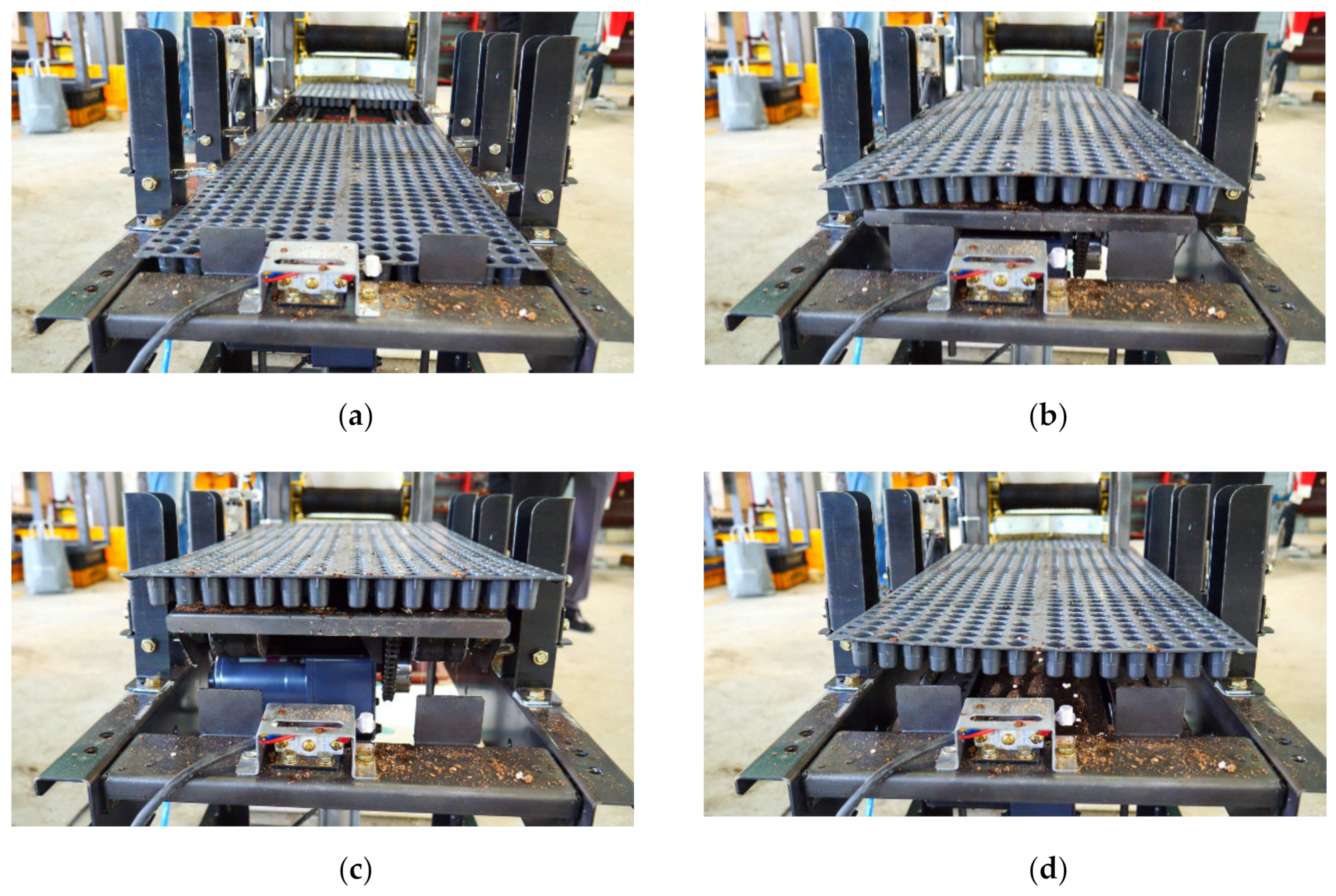
The operation method of the accumulating equipment is as follows. The pot tray that completed the seeding is transported to the elevator plate by the conveyor belt. When contact occurs between the end of the pot tray and the limit switch, the limit switch sends a stop signal to the motor to stop the conveyor belt, and simultaneously sends a start signal to the air compressor to operate the pneumatic-type actuator. In this instance, the pot tray and the elevator plate ascend and then descend owing to the stroke movement of the pneumatic-type actuator. The elevator plate returns to the original position as it descends, but the pot tray is accumulated onto the stopper bracket. When the elevator plate returns to its original position, the conveyor belt operates again to accumulate the second and third pot trays onto the stopper bracket in sequence in the same manner (Figure 12). Figure 13 shows a flowchart of the accumulating process.

Figure 12.
Operating process of automatic accumulating system: (a) start of operation → (b) ascending of elevator plate by pneumatic-type actuator → (c) maximum height of elevator plate (maximum stroke of actuator) → (d) descent of elevator plate (return of actuator stroke) and pot tray accumulating on bracket.
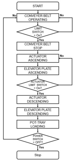
Figure 13.
Flowchart of automatic accumulating equipment process.
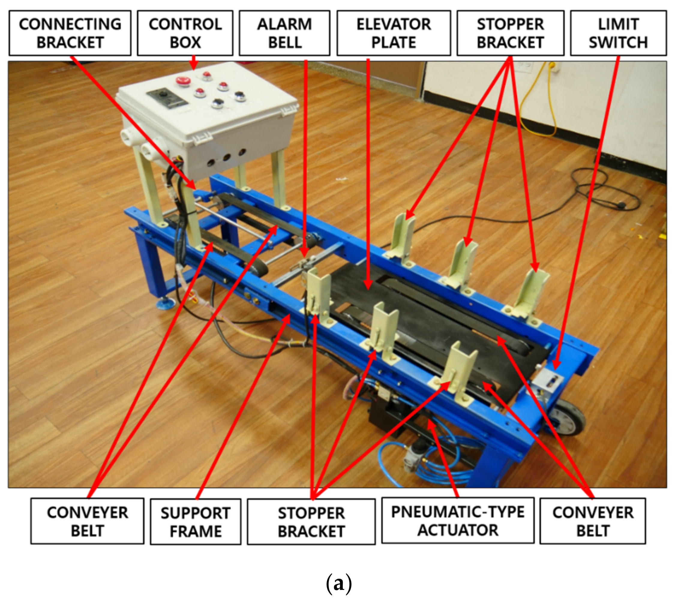
The developed accumulating equipment has a simple configuration and can be easily attached to or detached from a roller-type pot-seeding machine by a worker. The control box provides very convenient operation. Moreover, pot trays can be supported and accumulated in a stable manner using six stopper brackets, and the information on the degree of accumulating is confirmed by the alarm bell. Therefore, the developed accumulating equipment meets all conditions required for the accumulating equipment. Figure 14 shows the overall shape of the developed accumulating equipment.

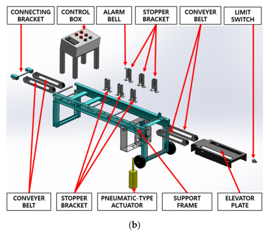
Figure 14.
Shape of the automatic accumulating equipment: (a) picture and (b) 3D model.
2.4. Factorial Experiment to Derive Appropriate Operating Conditions
If the operating conditions of the accumulating equipment are not appropriate, the seed bounce, in which the seeds in the pot tray cells are thrown out by the impact occurring in the accumulating process, may occur (Figure 15).
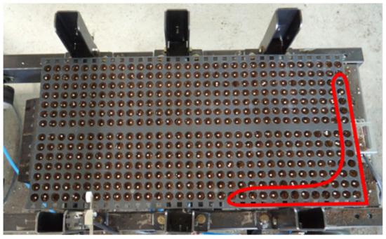
Figure 15.
Empty cells of pot tray by seed bounce from inappropriate operating condition.
The operating conditions that affect the seed bounce are the transport speed of the conveyor belt and the elevator plate ascending/descending time (one-time operating time of the actuator). If the transport speed of the conveyor belt is faster than the proper speed, a large impulse occurs when the pot tray and the limit switch collide, thus causing the seed bounce. Moreover, if the ascending/descending time of the elevator plate is shorter or longer than the proper time, the seed bounce occurs owing to the impulse generated when the pot tray and the stopper bracket collide or owing to the deformation generated from contact with the stopper bracket. Therefore, a factorial experiment was performed to minimize the seed bounce that occurs in the accumulating process.
The transport speed of the conveyor belt and the one-time operating time of the actuator were selected as test factors. The pot tray movement speed of a roller-type onion pot-seeding machine is 0.075 m/s [12]. To smoothly accumulate the pot tray that completed the seeding, the speed of the conveyor belt must be higher than the movement speed of the pot tray. Also, through a preliminary test, it was confirmed that excessive seed bounce occurred when the speed of the conveyor belt was higher than 0.3 m/s. As the transport speed of the conveyor belt can be adjusted from 0.03 m/s to 0.3 m/s in 0.03 m/s increments, it was set to seven steps of 0.09, 0.12, 0.15, 0.18, 0.21, 0.24, and 0.27 m/s in the factorial experiment. Through the preliminary test, it was confirmed that excessive seed bounce occurred when the actuator operating time was shorter than 0.7 s or longer than 1.6 s. Therefore, the actuator operating time was set to eight steps of 0.8, 0.9, 1.0, 1.1, 1.2, 1.3, 1.4, and 1.5 s. This leaves a total of 56 conditions (7 × 8) for the conveyor belt speed and the actuator operating time in the factorial experiment. Three repeated tests were conducted for each test condition, resulting in a total of 168 tests.
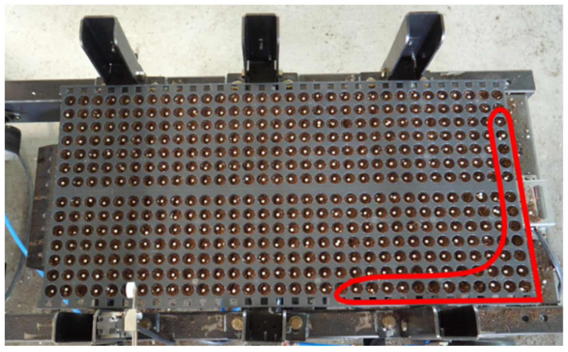
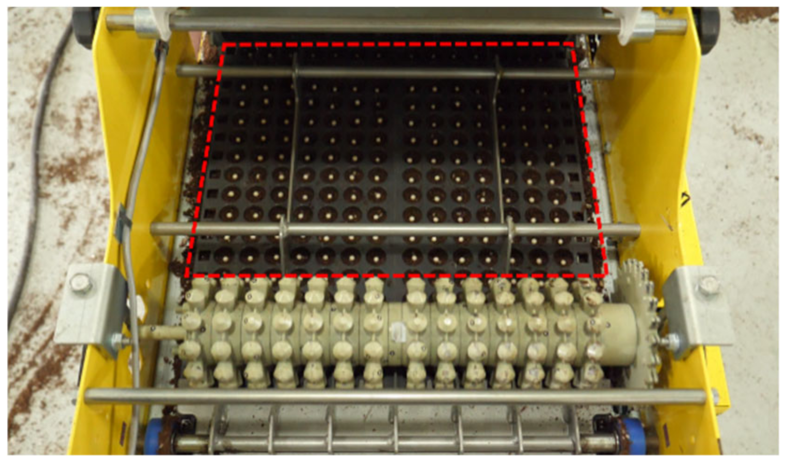
The developed accumulating equipment was attached to the existing roller-type pot-seeding machine to accumulate the pot trays that completed the seeding. After accumulating of pot trays, the number of seeds thrown out of the pot tray cells owing to impacts occurring in the accumulating process was measured. The seeding rate of the pot tray after the seeding device was checked before the tests, and the results showed 100% seeding rate (Figure 16). Thus, the empty cells of pot trays are due to the accumulating process.

Figure 16.
Measurement of the seeding rate by the seeding device.
The results of each test condition were analyzed using the average values of the three repeated tests as representative values. For the bed soil and seeds used in the tests, products commonly used in South Korea were applied.
3. Results and Discussion
3.1. Results of Factorial Experiment
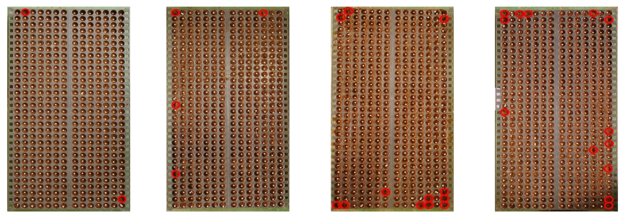
Figure 17 show the pot tray cells from which the accumulated seeds were thrown out.
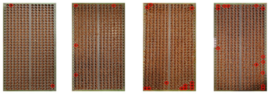
Figure 17.
Empty cells of pot tray for each actuator operating time and conveyor belt speed.
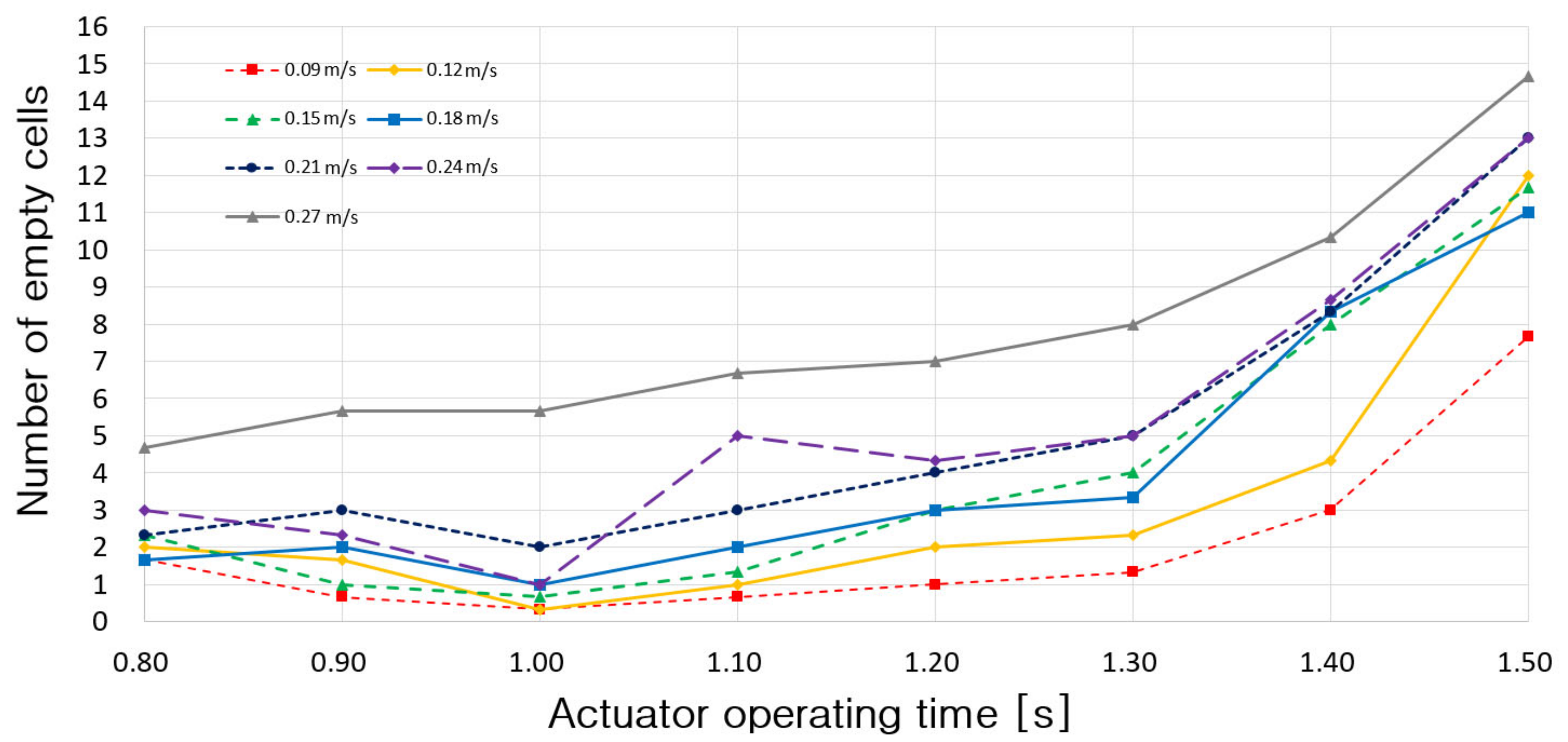
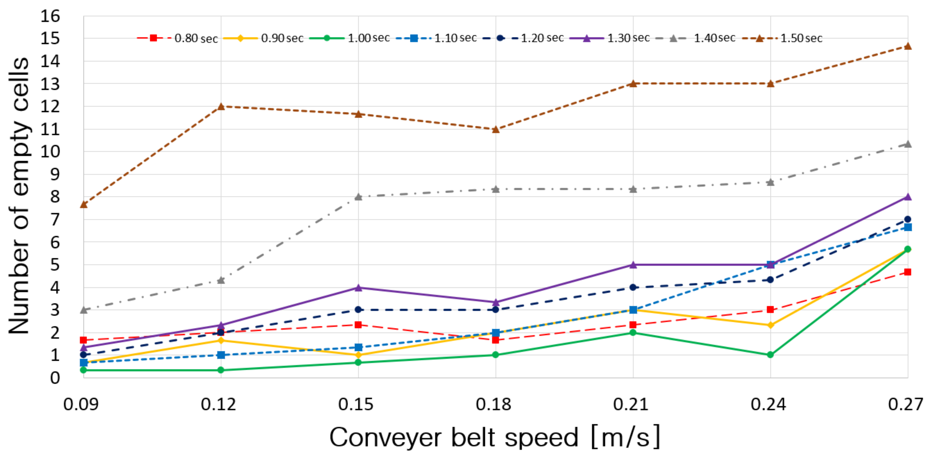
Figure 18 shows the number of empty cells according to the pneumatic-type actuator operating time. As the operating time increased, the number of empty cells showed a tendency to increase. Under all operating time conditions, the number of empty cells was lowest when the conveyor belt speed was 0.09 m/s and highest when it was 0.27 m/s. It appears that the number of empty cells increased as the conveyor belt speed increased because the impulse generated from the contact with the limit switch increased.
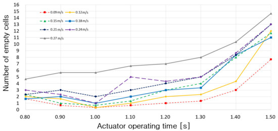
Figure 18.
Number of empty cells according to pneumatic-type actuator operating time.
Figure 19 shows the number of empty cells according to the conveyor belt speed. As the conveyor belt speed increased, the number of empty cells showed a tendency to increase. Under almost all conveyor belt speed conditions, the number of empty cells was lowest when the operating time of the pneumatic-type actuator was 1.0 s and highest when it was 1.5 s.
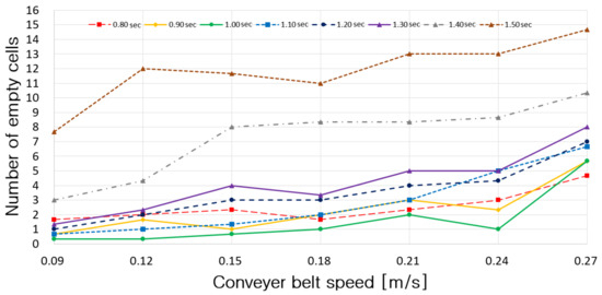
Figure 19.
Number of empty cells according to conveyor belt speed.
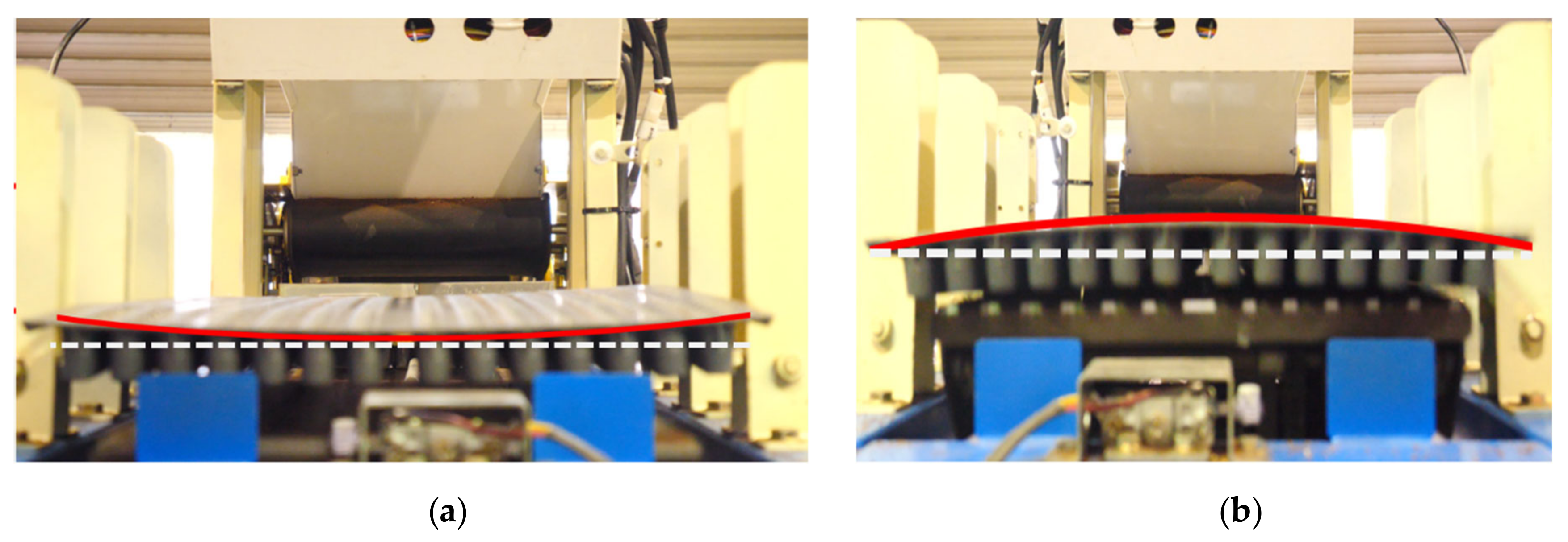
Given the operating time of the pneumatic-type actuator, the number of empty cells was high when the time was too short or too long. When the operating time was too short, it appears that the number of empty cells increased because the movement speed of the elevator plate increased, and thus the impulse generated when the pot tray was placed onto the stopper bracket increased. When the accumulating time was too long, it appears that the number of empty cells increased because the movement speed of the elevator plate decreased, and thus the deformation owing to the contact with the stopper bracket increased as the pot tray ascended (Figure 20). Since the relative motion or contact with the stopper bracket causes empty cells, most of the empty cells occurred at the edge of the pot tray.

Figure 20.
Deformation of pot tray by (a) dynamic impact and (b) contact.
To verify whether the conveyor belt speed and operating time of the pneumatic-type actuator had a significant impact on the seed bounce rate, an analysis of variance (two-way ANOVA) was conducted (Table 3). It was found that the conveyor belt speed, operating time of the pneumatic-type actuator and their interaction had a significant impact on the seed bounce rate at the 5% significance level. Therefore, the conveyor belt speed and operating time of the pneumatic-type actuator can be judged as major factors that affect the seed bounce rate.
Table 3.
Two-way ANOVA table for conveyor belt speeds and operating times of pneumatic-type actuator.
3.2. Derivation of Appropriate Operating Conditions
Table 4 lists the empty rates under each test condition. The empty rate is defined as the ratio of the number of empty cells in the pot tray to the number of total cells in the pot tray expressed as a percentage, as shown in (1). The condition with small empty rate means good operating condition having small seed bounce rate.
where = empty rate of the pot tray cells, %, = number of empty cells in the pot tray, = number of total cells in the pot tray.
Table 4.
Empty rate of pot tray cells (unit: %).
As a result of analyzing the average empty rate, it decreased as the conveyor belt speed decreased. For the operating time of the pneumatic-type actuator, the empty rate was lowest at 1.0 s, followed by 0.9, 0.8, 1.1, 1.2, 1.3, 1.4, and 1.5 s. For individual conditions, the empty rate was lowest at 0.07% when the actuator operating time was 1.0 s and the conveyor belt speed was 0.09 m/s or 0.12 m/s. Although the empty rate was the same under the two conditions, a faster conveyor belt speed leads to higher work efficiency. Therefore, the actuator operating time of 1.0 s and conveyor belt speed of 0.12 m/s were judged to be optimal operating conditions considering both the seed bounce rate and work efficiency.
4. Conclusions
In this study, accumulating equipment for a roller-type onion pot-seeding machine was developed, and the appropriate operating conditions were derived through factorial experiments.
The developed accumulating equipment was a flat plate type. Its main components were a conveyor belt, elevator plate, pneumatic-type actuator, stopper bracket, limit switch, control box, alarm bell, air compressor, and connecting brackets. The accumulating equipment operates as follows: when the pot tray that completed seeding is transported onto the elevator plate by the conveyor belt, the operation of the conveyor belt stops and the operation of the pneumatic-type actuator starts by the signal from limit switch. The elevator plate returns to its original position after being raised and lowered by the pneumatic-type actuator, but the pot tray is accumulated onto the stopper bracket. When the elevator plate returns to the original position, the conveyor belt operates again and accumulates the second and third pot trays on the stopper bracket in sequence in the same manner.
Factorial experiments were conducted to derive the appropriate operating conditions of the developed accumulating equipment. The experiments were conducted while the conveyor belt speed was varied from 0.09 to 0.27 m/s and the operating time of the pneumatic-type actuator varied from 0.8 to 1.5 s. The seed bounce was measured under each condition. As a result, a conveyor belt speed of 0.12 m/s and actuator operating time of 1.0 s were found to be the appropriate operating conditions for the lowest seed bounce rate and high work efficiency.
Factorial experiments were conducted under the conservative conditions that the seeded pot tray was not covered. Therefore, if there are no seeds to be thrown out in this experiment, there will be no empty cells in pot tray in the real seeding work.
The application of the derived operating conditions to the developed accumulating equipment is expected to reduce the labor load and increase the work efficiency required for onion seeding.
Author Contributions
Performed the experiments and analyzed the data, S.-J.H.; Writing—Original Draft Preparation, S.-J.H.; Writing—Review and Editing, J.-S.N.
Funding
This work was supported by the Korea Institute of Planning and Evaluation for Technology in Food, Agriculture, Forestry and Fisheries (IPET) through the Agriculture, Food and Rural Affairs Research Center Support Program funded by Ministry of Agriculture, Food and Rural Affairs (MAFRA) (716001-7). This research was also supported by the Basic Science Research Program through the National Research Foundation of Korea (NRF) funded by the Ministry of Education (NRF-2017R1D1A3B03033338).
Conflicts of Interest
The authors declare no conflicts of interest.
References
- Chae, H.S.; Kim, K.W.; Lee, K.S.; Kim, S.H.; Lee, K.M.; Choi, Y.W.; Park, K.S. The study on the moving rail-chair and electromotive scissors for preventing of the musculoskeletal disorders. J. Ergon. Soc. Korea 2010, 29, 139–144. [Google Scholar]
- Chae, H.S.; Kim, S.C.; Kim, K.W.; Lee, K.S.; Kim, H.C.; Park, K.S. Prevention of work-related musculoskeletal disorders in grapes pinching by using electro-motion scissors designed ergonomically. J. Ergon. Soc. Korea 2011, 30, 749–755. [Google Scholar] [CrossRef]
- Lee, E.J.; Suh, J.K. Effect of watering control on growth and bulb size of plug seedling in onion (Allium cepa L.) set production. Korean J. Hortic. Sci. Technol. 2007, 27, 167–173. [Google Scholar]
- Hwang, S.J.; Kim, D.H.; Nam, J.S. Design improvement research of onion port-seeding machine for increasing mechanization ratio. Conf. Korean Soc. Agric. Mach. 2016, 21, 93. [Google Scholar]
- Kang, J.H.; Hong, D.P. The package loading equipment development cutting both ends in the process of packaging lumber for improving the working environments. J. Soc. Korea Ind. Syst. Eng. 2008, 29, 135–142. [Google Scholar]
- Chang, Y.C.; Cho, S.I.; Yeo, W.Y. Development of a cabbage loader. Agric. Biosyst. Eng. 2002, 3, 73–78. [Google Scholar]
- Park, K.H.; Park, H.T.; Hye, S.H.; Lee, D.P. A Study on the Current State and Development Strategies of Raising Seedlings Industry; KREI: Seoul, Korea, 2011. [Google Scholar]
- Hwang, S.J. A Study on the Roller-Type Shape, Irrigation and Loading System of Roller-Type Pot-Seeding Machine. Master’s Thesis, Kangwon National University, Chuncheon, Korea, 2019; pp. 42–43. [Google Scholar]
- MAFRA. Development of High Efficiency Transplanting System for Labor-saving of Onion Production; Gyeongsangnam-do Agricultural Research & Extension Services: Jinju, Korea, 2015; pp. 158–160. [Google Scholar]
- Hwang, S.J.; Kang, H.S.; Oh, A.Y.; Nam, J.S. Operational characteristic analysis of roller-type pot-seeding machine for onion. J. Inst. Agric. Anim. Sci. 2017, 51, 145–158. [Google Scholar] [CrossRef]
- Jukam Field Machine Catalog. Available online: http://mnc.jukam.co.kr/theme/basic/catalogue/catalogue3.pdf/ (accessed on 11 May 2019).
- Hwang, S.J.; Park, J.H.; Lee, J.Y.; Nam, J.S. Development of automatic pot tray loading equipment for roller-type pot-seeding machine. Conf. Korean Soc. Agric. Mach. 2018, 23, 85. [Google Scholar]


© 2019 by the authors. Licensee MDPI, Basel, Switzerland. This article is an open access article distributed under the terms and conditions of the Creative Commons Attribution (CC BY) license (http://creativecommons.org/licenses/by/4.0/).