A YOLOv2 Convolutional Neural Network-Based Human–Machine Interface for the Control of Assistive Robotic Manipulators


Abstract
:1. Introduction
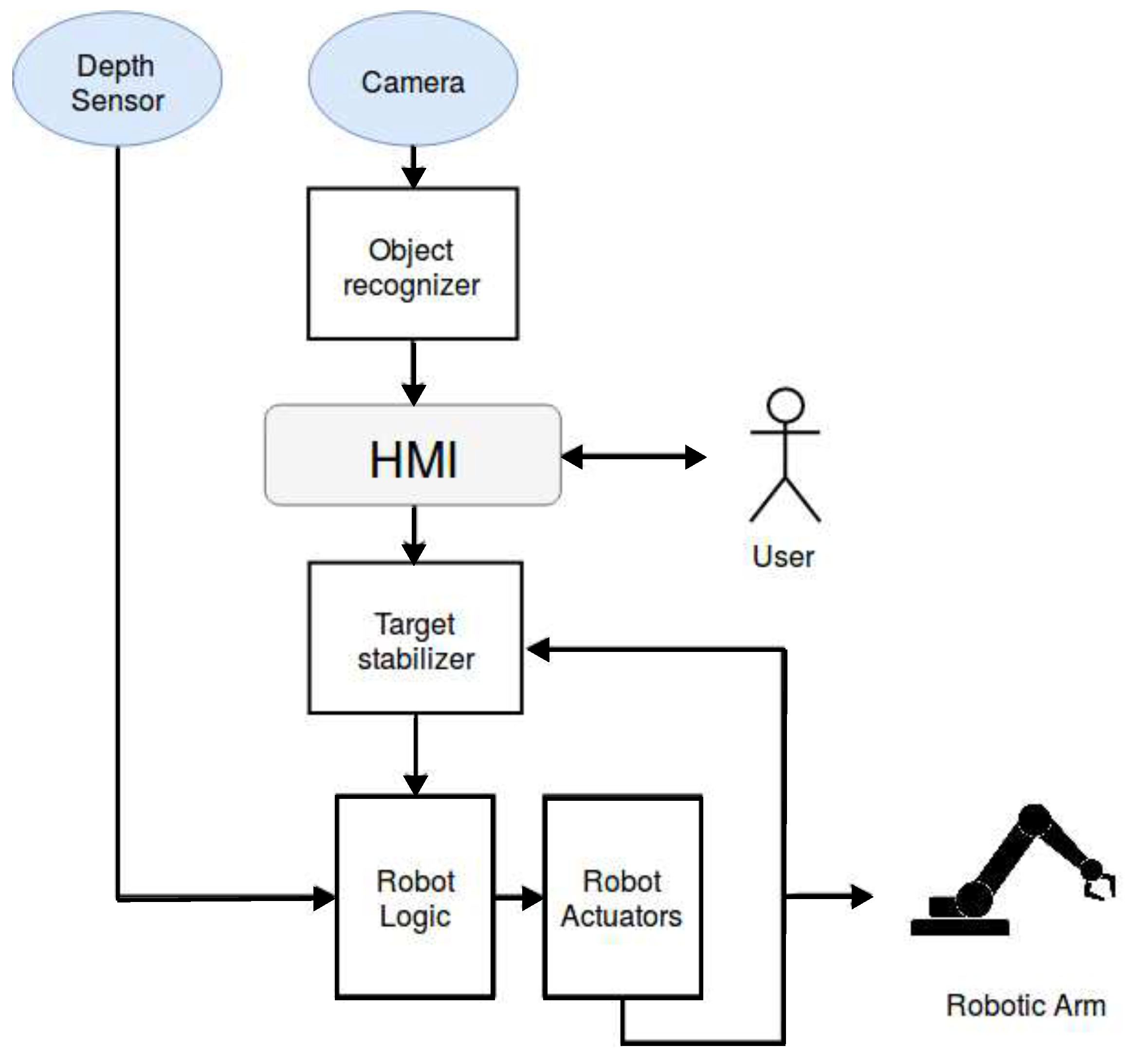
2. Concept
3. Methods and Materials
3.1. Hardware Setup
- Raspberry PI 3B board: This is the platform that runs the system software with the sole exception of the AI algorithm, as explained in Section 3.2. It interfaces all the other hardware components directly or through dedicated boards (e.g., the Phydget board, as successively explained).
- Phydget v1.1 board: It is a commercial motors driver board. Its use is necessary since the Raspberry PI 3B board is not able to provide the sufficient power to the five motors. A dedicated driver motor board allows choosing a platform for the sub-system independently by its ability to drive the motors.
- 5MP Raspberry Camera module: The hardware part of the conceptual subsystem Camera is a low cost monocular camera that provides images from which some information is extracted for the control of motion in the space. The acquired images are with 8 bits for each color (RGB).
- HCSR04 proximity sensor: The hardware component of Depth Sensor was realized through a low cost ultra-sound proximity sensor. As described in Section 2, it is necessary to estimate the distance along the axis of the camera frame between the camera and the interest object (depth). Due to the low cost nature of the sensor, the accuracy of the measurement is low, but it is compensated by the IBVS approach, as explained in Section 3.4.3.
- Force sensor: The force sensor is used to avoid breaking the end-effector or damaging the object while the manipulator grabs them.
- Raspberry 7” touch screen display: As described in Section 2, the HMI is necessary to show the user the selectable objects to interact with. In addition, it might also be exploited by users with a limited level of manual skills. Thus, a touch screen display has been used.
3.2. Software Architecture
- Hardware layer
- Application Logic Unit Layer
- Human–Machine Interface Layer
3.3. Hardware Layer
- Camera node: The camera node handles all the frames taken by the Raspberry Camera Module and it represents the software part of the Camera conceptual block. In addition to the data acquisition, the Camera Node modifies the resolution and the brightness of the images to provide better frame quality. To do that, a topic is exposed. To reduce the latency and increase the fluidity of the stream of frame, the camera node performs an image compression by reducing the quality of the original image through an 8-bit truncation of the colors, i.e. the images stream are converted to JPEG and encapsulated inside a ROS standard message to be exposed in a topic.
- Proximity node: The Proximity node collects the data provided by the proximity sensor and by data processing to evaluate the distance from the desired object. Since the data provided represent the time to go and return of the ultrasound signal, the measured distance can be calculated simply multiplying then times the sound speed divided by 2. The distance measurements are then transmitted as a message on a dedicated exposed topic. The Proximity node together with the hardware proximity sensor realize the Depth Sensor conceptual subsystem.
- Controller Motor Node: The Raspberry board is not able to provide the power for five motors; thus, the Phydget board is used. However, the latter cannot interpret the data provided by The Application Processor, which sends the position of joints as angles. In this layer, every position is converted into the format required by the Phidget API without changing the upper layer output data. The Controller Motor Node, together with the Phydget board, implement the Robotic Actuators conceptual subsystem.
3.4. Application Logic Unit Layer
3.4.1. YOLO Deep Neural Network
- : Given a grid cell with at least one object, it represents the conditional probability for one of them to belong to the ith class.
- : It represents the confidence of each bounding box inside a cell grid.
3.4.2. Kernelized Correlation Filter Algorithm
3.4.3. Robot Movement Control System
- IDLE: Before receiving a user command, the system remains in the IDLE state. It corresponds to the initial position of the robotic arm. When a new command is received—i.e., a new target position—the system transits to the XY Kalman state.
- XY Kalman: In this state, the robotic arm is forced to align the target position (X,Y) with respect a predefined point , called Camera Features. A square of side of pixels is defined around the target position. When the difference between the (X,Y) coordinates of the object and coordinates of the fixed point is enclosed in the square, the end-effector is considered aligned. Thus, the system transits to the APPROACHING Kalman state.
- APPROACHING Kalman: In this state, the robotic arm approaches the object by moving along a direction orthogonal to the camera plane axis. If the movement leads to a significant misalignment on the (X,Y) plane (greater than 35 pixels), the systems transits back to the XY Kalman state. The information provided by the Proximity Node is used to monitor the distance between the object and the end-effector. When the end-effector reaches a fixed distance, the system transits to the STOP state.
- STOP: The STOP state is used by the system to perform simple movements that depend on the task required. For instance, in the case of a pressure of a key, the manipulator touches the button. After the completion of the task, the system comes back to the IDLE state.
3.4.4. Image Base Visual Servoing
3.5. Human–Machine Interface Layer
- Touch Screen
- Manual Raster Scanning (Two Sensors)
- Time Raster Scanning (One Sensor)
4. Results
4.1. System Accuracy Tests
4.2. Preliminary Tests with the End-Users
- Touch (High motor-skills) (12 people)
- Double sensors (Medium motor-skills) (6 people)
- Single sensor (Low motor-skills) (2 people)
- Grabbing objects, such as bottles or glasses
- Picking up objects fallen on floor
5. Conclusions
Author Contributions
Funding
Acknowledgments
Conflicts of Interest
Abbreviations
| AI | Artificial Intelligence |
| API | Application Programming Interface |
| CNN | Convolutional Neural Network |
| DoF | Degrees of Freedom |
| FCFNN | Fully Connected Feed-forward Neural Network |
| FSM | Finite State Machine |
| FPS | Frame Per Second |
| HMI | Human–Machine Interface |
| IBVS | Image Based Visual Servoing |
| KCF | Kernelized Correlation Filter |
| mAP | mean Average Precision |
| ML | Machine Learning |
| R-CNN | Region of Interest Convolutional Neural Network |
| ReLU | Rectified Linear Units |
| ROS | Robotic Operating System |
| YOLO | You Only Look Once |
References
- Campeau-Lecours, A.; Lamontagne, H.; Latour, S.; Fauteux, P.; Maheu, V.; Boucher, F.; Deguire, C.; Caron L’Ecuyer, L.J.C. Kinova Modular Robot Arms for Service Robotics Applications. Int. J. Rob. Appl. Technol. 2017, 5, 49–71. [Google Scholar] [CrossRef]
- Dynamics, E. iARM. 2018. Available online: http://www.exactdynamics.nl/site/?page=iarm (accessed on 30 May 2019).
- Tang, J.; Zhou, Z.; Yu, Y. A Hybrid Computer Interface for Robot Arm Control. In Proceedings of the 2016 8th International Conference on Information Technology in Medicine and Education (ITME), Fuzhou, China, 23–25 December 2016; pp. 365–369. [Google Scholar]
- Arrichiello, F.; Di Lillo, P.; Di Vito, D.; Antonelli, G.; Chiaverini, S. Assistive robot operated via P300-based brain computer interface. In Proceedings of the 2017 IEEE International Conference on Robotics and Automation (ICRA), Singapore, 29 May–3 June 2017; pp. 6032–6037. [Google Scholar]
- Ka, H.W.; Chung, C.S.; Ding, D.; James, K.; Cooper, R. Performance evaluation of 3D vision-based semi-autonomous control method for assistive robotic manipulator. Disabil. Rehabil. Assist. Technol. 2018, 13, 140–145. [Google Scholar] [CrossRef] [PubMed]
- Tolba, H.; El_Torgoman, A.S. Towards the improvement of automatic recognition of dysarthric speech. In Proceedings of the 2009 2nd IEEE International Conference on Computer Science and Information Technology, Beijing, China, 8–11 August 2009; pp. 277–281. [Google Scholar]
- Raghavendra, P.; Rosengren, E.; Hunnicutt, S. An investigation of different degrees of dysarthric speech as input to speaker-adaptive and speaker-dependent recognition systems. Augmentative Altern. Commun. 2001, 17, 265–275. [Google Scholar] [CrossRef]
- Palla, A.; Frigerio, A.; Meoni, G.; Fanucci, L. Object Detection and Spatial Coordinates Extraction Using a Monocular Camera for a Wheelchair Mounted Robotic Arm. In Proceedings of the International Conference on Smart Objects and Technologies for Social Good, Venice, Italy, 30 November–1 December 2016; pp. 224–232. [Google Scholar]
- Palla, A.; Meoni, G.; Fanucci, L.; Frigerio, A. Position Based Visual Servoing control of a Wheelchair Mounter Robotic Arm using Parallel Tracking and Mapping of task objects. EAI Endorsed Trans. Ambient Syst. 2017, 17, e1. [Google Scholar] [CrossRef]
- Palla, A.; Sarti, L.; Frigerio, A.; Fanucci, L. Embedded implementation of an eye-in-hand visual servoing control for a wheelchair mounted robotic arm. In Proceedings of the 2016 IEEE Symposium on Computers and Communication (ISCC), Messina, Italy, 27–30 June 2016; pp. 274–277. [Google Scholar]
- Rabhi, Y.; Mrabet, M.; Fnaiech, F. Intelligent control wheelchair using a new visual joystick. J. Healthcare Eng. 2018, 2018. [Google Scholar] [CrossRef] [PubMed]
- Quigley, M.; Conley, K.; Gerkey, B.P.; Faust, J.; Foote, T.; Leibs, J.; Wheeler, R.; Ng, A.Y. ROS: An open-source Robot Operating System. ICRA Workshop on Open Source Software. 2009. Available online: https://www.ros.org/ (accessed on 30 May 2019).
- Lowe, D.G. Distinctive image features from scale-invariant keypoints. Int. J. Comput. Vision 2004, 60, 91–110. [Google Scholar] [CrossRef]
- Dahl, G.E.; Sainath, T.N.; Hinton, G.E. Improving deep neural networks for LVCSR using rectified linear units and dropout. In Proceedings of the 2013 IEEE International Conference on Acoustics, Speech and Signal Processing, Vancouver, BC, Canada, 26–31 May 2013; pp. 8609–8613. [Google Scholar] [CrossRef]
- Hager, W.W.; Zhang, H. A new conjugate gradient method with guaranteed descent and an efficient line search. SIAM J. Optim. 2005, 16, 170–192. [Google Scholar] [CrossRef]
- Sathyanarayana, S. A gentle introduction to backpropagation. ACM Digital Library 2014, 7, 1–15. [Google Scholar]
- Girshick, R.; Donahue, J.; Darrell, T.; Malik, J. Rich feature hierarchies for accurate object detection and semantic segmentation. In Proceedings of the the IEEE Conference on Computer Vision and Pattern Recognition (CVPR), Columbus, OH, USA, 24–27 June 2014; pp. 580–587. [Google Scholar]
- Goodfellow, I.; Bengio, Y.; Courville, A. Deep Learning. 2016. Available online: http://www.deeplearningbook.org (accessed on 30 May 2019).
- Girshick, R. Fast r-cnn. In Proceedings of the The IEEE International Conference on Computer Vision (ICCV), Santiago, Chile, 13–16 December 2015; pp. 1440–1448. [Google Scholar]
- Ren, S.; He, K.; Girshick, R.; Sun, J. Faster r-cnn: Towards real-time object detection with region proposal networks. In Proceedings of the Advances in Neural Information Processing Systems 28 (NIPS 2015), Montreal, QC, Canada, 7–12 December 2015; pp. 91–99. [Google Scholar]
- Lowe, D.G. Object recognition from local scale-invariant features. In Proceedings of the ICCV 1999, Kerkyra, Corfu, Greece, 20–25 September 1999; pp. 1150–1157. [Google Scholar]
- Peng, X.; Feris, R.S.; Wang, X.; Metaxas, D.N. A recurrent encoder-decoder network for sequential face alignment. In Proceedings of the European Conference on Computer Vision, Amsterdam, The Netherlands, 11–14 October 2016; pp. 38–56. [Google Scholar]
- Redmon, J.; Farhadi, A. YOLO9000: Better, faster, stronger. In Proceedings of the IEEE Conference on Computer Vision and Pattern Recognition, Honolulu, HI, USA, 21–26 July 2017; pp. 7263–7271. [Google Scholar]
- Redmon, J.; Divvala, S.; Girshick, R.; Farhadi, A. You only look once: Unified, real-time object detection. In Proceedings of the IEEE Conference on Computer Vision and Pattern Recognition, Las Vegas, NV, USA, 26 June–1 July 2016; pp. 779–788. [Google Scholar]
- Deng, J.; Dong, W.; Socher, R.; Li, L.J.; Li, K.; Fei-Fei, L. ImageNet: A Large-Scale Hierarchical Image Database. In Proceedings of the 2009 IEEE Conference on Computer Vision and Pattern Recognition, Miami Beach, FL, USA, 22–24 June 2009; pp. 248–255. [Google Scholar]
- Lin, T.Y.; Maire, M.; Belongie, S.; Hays, J.; Perona, P.; Ramanan, D.; Dollár, P.; Zitnick, C.L. Microsoft coco: Common objects in context. In Proceedings of the European Conference on Computer Vision, Zurich, Switzerland, 6–12 September 2014; pp. 740–755. [Google Scholar]
- Chollet, F. Keras: The Python Deep Learning library. Available online: https://keras.io (accessed on 30 May 2019).
- Henriques, J.F.; Caseiro, R.; Martins, P.; Batista, J. High-speed tracking with kernelized correlation filters. IEEE Trans. Pattern Anal. Mach. Intell. 2014, 37, 583–596. [Google Scholar] [CrossRef] [PubMed]
- Siciliano, B.; Sciavicco, L.; Villani, L.; Oriolo, G. Robotics: Modelling, Planning and Control; Springer Science & Business Media: Berlin, Germany, 2010. [Google Scholar]


| Tracking Algorithms | RViz sim. Accuracy | Prototype Accuracy |
|---|---|---|
| Only YOLOv2 | 94% | 43% |
| YOLOv2 + KCF | 100% | 78% |
© 2019 by the authors. Licensee MDPI, Basel, Switzerland. This article is an open access article distributed under the terms and conditions of the Creative Commons Attribution (CC BY) license (http://creativecommons.org/licenses/by/4.0/).
Share and Cite
Giuffrida, G.; Meoni, G.; Fanucci, L. A YOLOv2 Convolutional Neural Network-Based Human–Machine Interface for the Control of Assistive Robotic Manipulators. Appl. Sci. 2019, 9, 2243. https://doi.org/10.3390/app9112243
Giuffrida G, Meoni G, Fanucci L. A YOLOv2 Convolutional Neural Network-Based Human–Machine Interface for the Control of Assistive Robotic Manipulators. Applied Sciences. 2019; 9(11):2243. https://doi.org/10.3390/app9112243
Chicago/Turabian StyleGiuffrida, Gianluca, Gabriele Meoni, and Luca Fanucci. 2019. "A YOLOv2 Convolutional Neural Network-Based Human–Machine Interface for the Control of Assistive Robotic Manipulators" Applied Sciences 9, no. 11: 2243. https://doi.org/10.3390/app9112243
APA StyleGiuffrida, G., Meoni, G., & Fanucci, L. (2019). A YOLOv2 Convolutional Neural Network-Based Human–Machine Interface for the Control of Assistive Robotic Manipulators. Applied Sciences, 9(11), 2243. https://doi.org/10.3390/app9112243