1. Introduction
Stroke often results in a combination of cognitive, sensory, and motor impairments. Now, it has become one of the main diseases threatening human survival and health [
1,
2]. The most common impairment of stroke is hemiparesis, which results in dyskinesia of some parts of the body. It reflects not only in the upper and lower limbs, but also in the loss of motor function of the hand [
2]. It was verified by rehabilitation medicine that exercises with high strength and repeatability can stimulate cortical layer to recombine to help the stroke patients learn to control the motion again [
3]. The application of robotics and related technologies has greatly promoted the development of clinical techniques [
4,
5,
6]. Recent researches have shown that exoskeleton devices are feasible and effective for hand rehabilitation [
7,
8].
Hand is one of the most important limbs of humans, and the rehabilitation of hand motor function can be assisted by exoskeleton robots [
9,
10,
11]. Many dexterous and advanced mechanisms of hand exoskeletons have been studied and developed. But not all of them are developed for hand rehabilitation. For example, some of them are designed for master–slave systems [
12,
13] and some others are designed as force-feedback devices [
14]. They are limited in the number of independently actuated degrees of freedom. Their mechanism design ideas can be used as a reference for the study of the hand rehabilitation exoskeleton [
15,
16,
17,
18,
19]. However, due to the special rehabilitation application, we need to modify the mechanism to make sure that exoskeleton and each finger joint have the same center of rotation, which avoids secondary injuries when the exoskeleton has direct contact with the hand [
20].
Control system and methods study of the exoskeleton manipulator are also important research categories. The most popular control system of rehabilitation training is a closed loop control system with sensors [
20], such as force sensors [
21,
22] and electromyography (EMG) sensors [
23]. The most commonly reported rehabilitation modes provided by developed rehabilitation exoskeletons are the continuous passive motion (CPM) and the active assisted movement (AAM). Some exoskeleton systems are designed for passive rehabilitation mode based on CPM [
24]. The passive mode is useful for preventing muscle contractures in early rehabilitation stage. But its effectiveness in the mid-to-late stage is limited when patients can initiate movement but have difficulty in completing it. Some other exoskeleton systems are designed for active rehabilitation control mode based on AAM [
25]. The active mode could make up the shortcomings of passive mode in mid-to-late rehabilitation stage. Nowadays, most systems have only one of the modes mentioned above, which is not suitable for the whole scale of rehabilitation, especially the middle rehabilitation stage when patients have some residual motion capability but have not yet reached the normal level. Therefore, if there were two kinds of rehabilitation modes that could switch actively according to patients’ rehabilitation status, it can promote hand rehabilitation more effectively.
In addition, the rehabilitation exercises in a virtual environment will be more interesting. It will induce the patients to take the exercise more actively [
26,
27]. The patients will be more desired to take the exercise so the effect of rehabilitation will be better, such as Hand Mentor Pro
TM (Motus Nova, Atlanta, GA, USA) [
28]. But because the rehabilitation interface of this kind of device mainly adopts hardware system based on PC or dedicated closed hardware system, it is too expensive, not open and not portable [
29].
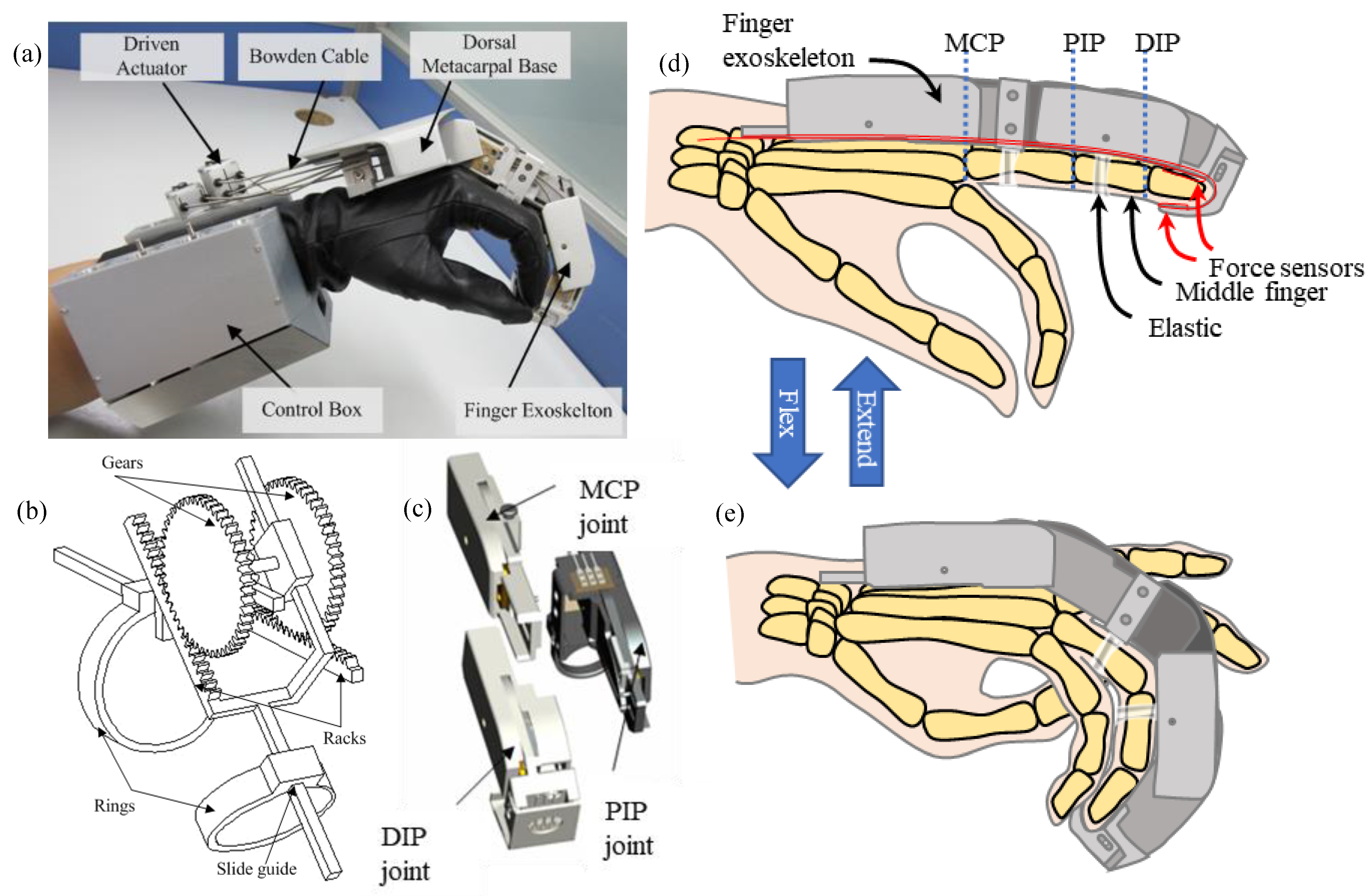
In this paper, a new kind of hand exoskeleton system has been introduced. The introduced mechanism can adapt to fingers with different thicknesses and lengths and prevent the secondary injuries. Hardware system and human–robot interactive rehabilitation software based on Android system are also designed. The method for passive rehabilitation based on proportional derivative (PD) inverse dynamic control and the method for active rehabilitation based on impedance control are established respectively. Two kinds of rehabilitation modes could switch actively according to contact forces between fingers and exoskeleton in different rehabilitation stages. Finally, the feasibility of the control system and the control strategy has been verified through the experiments.
4. Active and Passive Control
4.1. Control Strategy
The overall control strategy of the hand rehabilitation exoskeleton designed in this paper is shown in
Figure 4. If it is detected by the sensors that the patient’s hand can do flexion-extension, then the active rehabilitation mode will be adopted, and the exoskeleton will follow the motion of the fingers. Otherwise, the passive rehabilitation mode will be adopted, and the exoskeleton will actuate the fingers to move. The motion ability of the hand is judged by the contact force between the exoskeleton and the hand detected by the force sensors, which is used for the real-time switch of the control strategy between active and passive rehabilitation modes.
In the passive rehabilitation mode, the control system adopts a highly robust and reliable PD method to control the motion of the patient’s finger to the functional position. In this mode, the patient or physician can choose suitable velocity gear for the inverse dynamics control to implement in early rehabilitation stage. Then the exoskeleton helps the finger follow the desired trajectory and move to the functional position at the preset velocity.
In the active rehabilitation mode, the control system adopts impedance control to track the force on the fingertip and track the desired trajectory by the position control loop. In this mode, the patient or physician can preset the resistance according to the patient’s movement ability. Then the exoskeleton tries to follow the patient’s motion and keep the force between exoskeleton and fingertip around the preset resistance to improve the movement ability.
The active plus passive rehabilitation mode is designed based on the two basic rehabilitation modes, detecting the force between the exoskeleton and the patient’s fingertip through the force sensors distributed on the tip. The switch of the two modes is determined by the threshold value. In this mode, if the patient could exert force actively, the control system will switch to the active mode and follow the patient’s motion. Otherwise, whenever the patient cannot exert enough force to move the fingers, the control system will switch to the passive mode to help the finger track the desired trajectory to reach the functional position at a preset velocity gear. In order to keep the system stable and compliant, in the control system, the impedance parameter is adjusted to be close to the input velocity parameter in the passive mode to provide smooth rehabilitation experience for the patients.
In the interaction rehabilitation software, when the virtual finger touches the contact plate, the collision signal is sent to the control system that will judge the functional position according to the signal. In the overall rehabilitation control strategy, the switch is accomplished by the sequence controller.
4.2. Modeling
The coordinates of the exoskeleton fingers are shown in
Figure 5. Every finger has four joints, which are joint MCP with two DOFs, i.e., yaw (MCP1) and pitch (MCP2), joint PIP and joint DIP. The joint angles of MCP are
,
, the angles of joint PIP and joint DIP are
,
respectively. The lengths of links are
,
,
,
, where
.
• Kinematics:
Due to the coupling effect between joint PIP and joint DIP, the ratio is
, and MCP1 is an adaptive DOF without actuating. The kinematic relationship between the tip position and the joint angles is:
• Dynamics:
The dynamic model of the exoskeleton finger is the foundation of controller design and simulation study. In this paper, the Lagrange method is adopted to build the dynamic model in joint space in order to facilitate the study of the control method. For the exoskeleton model moving in the
n-dimensional space, the Lagrange dynamic equation in joint space is:
where
is the inertia matrix,
,
is the centripetal and Coriolis force,
,
is gravity item,
is the joint actuating torque vector,
,
is the force on the exoskeleton fingertip,
. Considering the coupling effect between joint PIP and joint DIP, i.e., the two SPRM with parallel mechanism are joined together and actuated by the same motor, the motor torque is the sum of the torques of the two coupling joints.
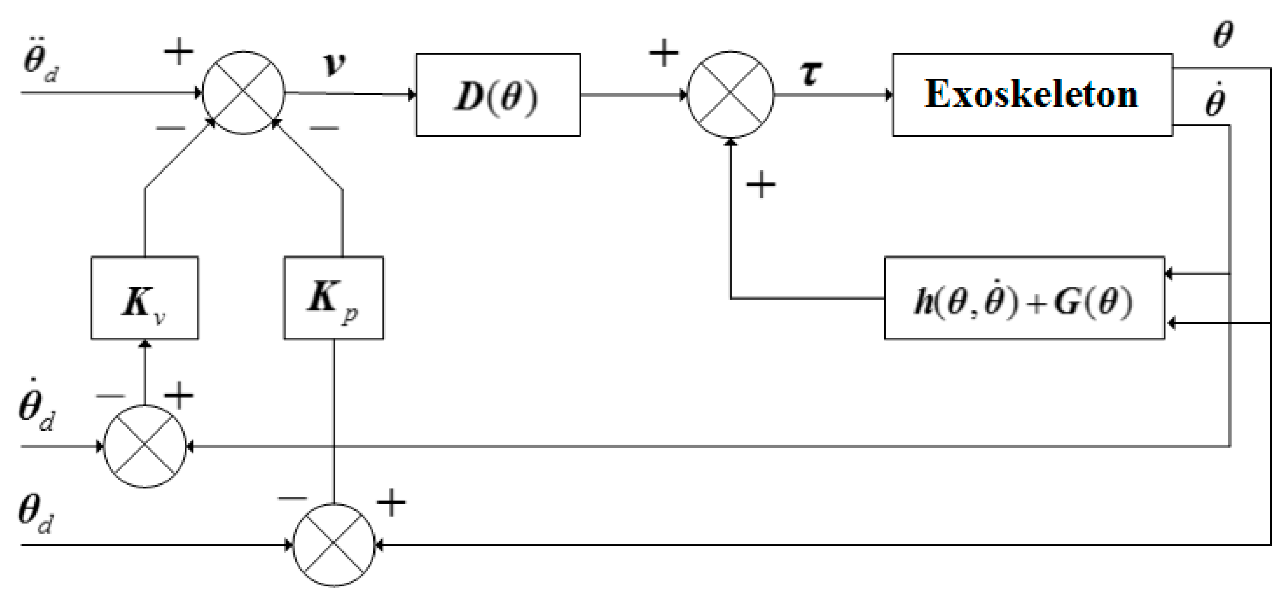
4.3. Passive Control
Because of the partial or complete loss of motor function, in general, the stroke patients cannot finish the whole rehabilitation training, i.e., they cannot actively control their hands to the functional position. Under this circumstance, the control system of the hand rehabilitation exoskeleton can detect the contact parameters by the force sensors on the fingertips and switch to the passive mode, where the fingers are actuated to the functional position by the exoskeleton. In the passive rehabilitation mode, the goal is to actuate the joints to follow the desired trajectory and move to the preset functional position. The PD control method based on the inverse dynamic compensation is adopted and the control block diagram is shown in
Figure 6.
Defining the trajectory error
and velocity error
,
is the desired trajectory of the exoskeleton in joint space,
is the actual trajectory in joint space. Assuming the desired trajectory
are bounded, and by inducing
and substituting it into the dynamic equation in joint space, we have the controller as follows:
substituting Equation (3) into the dynamic equation Equation (2), and we have,
if
is invertible, then from (4) we have:
setting
as the following equation:
substituting (5) into (6), the error equation of the system can be obtained as follows:
introducing the PD control method into (7):
where
and
are positive diagonal matrices. If we substitute Equations (6) and (8) into Equation (3), the passive rehabilitation control equation can be obtained as:
4.4. Active Control
The active rehabilitation mode is that the patients do flexion and extension of the finger actively and the exoskeleton tracks and adapts to the motion status of the patients automatically. The controller does not directly control the exoskeleton to reach the desired configuration, but control it to follow the patient’s motion according to the motor ability. According to the impedance model and the input of the force signals on the tips, the trajectory of the exoskeleton finger is planned in real time. The actual motion status parameters are obtained by detecting the output
of the exoskeleton, thus we have the control variable
. The position controller is used to realize the real-time track of the patient’s fingers. The control block diagram is shown in
Figure 7.
The relationship between the joint space of the exoskeleton and the Cartesian space is
where
is the forward kinematic relationship of the exoskeleton. Taking the derivative of Equation (10) and we have the relationship between the accelerations in joint space and Cartesian space:
During the contact of finger and exoskeleton, the relationship between finger and exoskeleton is a second order dynamic relation, and we simplify it as a linear spring model. In Cartesian space, the impedance model is as follows:
where
,
,
are objective inertia matrix, objective damping matrix, and objective stiffness matrix, respectively.
and
are respectively the actual position and desired position of the exoskeleton fingertip.
is the contact force between the finger and the exoskeleton.
Rewriting the impedance model Equation (12) and substituting it into Equations (10) and (11), we have:
Due to the integral of Equation (13) and
has been obtained, the PID control method is adopted in the position control loop. In the active rehabilitation mode, the position error
is used to make the motor output torque
actuate the exoskeleton to follow the desired trajectory, and the relationship between
and
is as follows:
where
,
,
are the proportional, integral, and differential gains of the controller, respectively.
5. Experiments
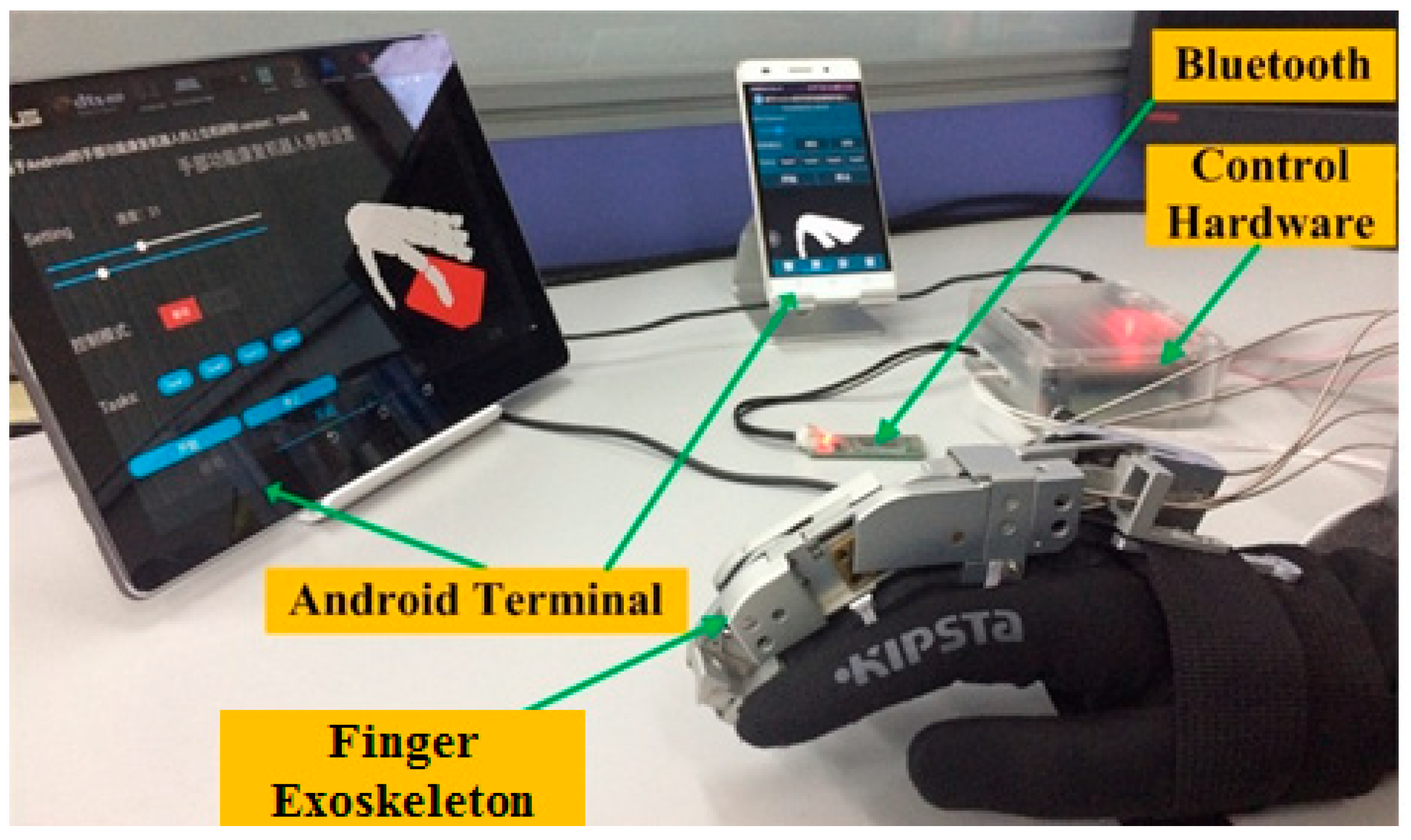
5.1. Experimental Setup
The experimental setup includes the hand exoskeleton, the hardware of the control system, the Motorola tablet based on Android system, and the 12 V regulated power supply, as shown in
Figure 8. A pair of force sensors (Tekscan Company’s flexible pressure sensor, 1 lbs) is placed on the top and bottom of the PIP joint of the exoskeleton finger to detect the contact force between the fingertip and the exoskeleton.
The operator can use the tablet to set the start, stop, motion velocity, and contact detection, and send instructions to the exoskeleton by the Bluetooth communication module. Meanwhile, the control system of the exoskeleton detects the motion status of the patient by force sensors in order to decide the rehabilitation mode.
The human–robot interaction rehabilitation software can receive the motion information of the patient’s hand in the control system, and the model is shown in the virtual environment in real time to induce the patient to participate in rehabilitation training actively. During the experiment, we choose a healthy human as the rehabilitation subject. The information about the subject’s three phalanxes of the middle finger is shown in
Table 1. The finger mass is estimated according to the volume [
31]. All ethical issues with the study design are in accordance with the local ethical regulations.
5.2. Experimental Implementation
• Passive rehabilitation mode:
The motion ranges of the joints of the volunteer’s middle finger are measured by the NDI Optotrak 3-D measurement system, based on which the desired trajectory of the middle finger in joint space is set as:
During this experiment, the subject sat before the tablet, wore the glove with exoskeleton on hand, and kept the finger relaxed. The exoskeleton drove the finger to do flexion-extension and track the desired trajectory to make the virtual finger touch the virtual box in the Android tablet. The control block diagram is shown in
Figure 6. Control parameters in Equation (9) are
,
. The experiment time was 5 s and the data sampling period was 10 ms.
• Active rehabilitation mode:
The active rehabilitation mode uses impedance algorithm to drive the exoskeleton by the force on the tip collected by the force sensors.
During this experiment, the subject sat before the tablet and wore the glove with exoskeleton on hand. The subject was required to exert force on the finger and keep the finger relaxed alternately to stimulate patients with residual motor ability. In the active rehabilitation mode, the exoskeleton follows the hand. The desired trajectory of the active rehabilitation experiment is from the real-time simulation synchronous with the experiment. Control block diagram of the simulation is shown in
Figure 7. The contact force in the control law Equation (14) is from the real-time data obtained from the experiment. Other control parameters in Equation (13) during simulation are
,
,
. The parameters in Equation (14) are chosen as
0.5,
= 0.0625,
= 0.4. In the simulation, Equation (2) is adopted as the exoskeleton model, and the dynamic parameters are shown in
Table 2. During the experiment, the sampling period is 10 ms, and the motion time is 28 s.
• Active plus passive rehabilitation mode:
The active plus passive experiment of the hand rehabilitation exoskeleton is the combination of active and passive rehabilitation modes.
During this experiment, the subject sat before the tablet and wore the glove with exoskeleton on hand. The subject was required to exert force on the finger and occasionally relax the finger to stimulate patients with incomplete motor ability. The sampling period was 10 ms, and the motion time was 5 s. The threshold value of the force on the fingertip was preset to switch the mode between the active and passive rehabilitation automatically. In this experiment, the threshold value was set as 0.6 N from pre-experiments. The desired trajectory of the experiment was also obtained by the real-time simulation. Specifically, if , then the system considers that the patient is willing to and able to move actively, hence the control system will switch to the active mode. Otherwise, if , then the passive rehabilitation mode is chosen. In order to ensure the stability of the motion, the angular velocities of the joints were calculated by the passive control, and the trajectories were obtained by the integral of velocity.
5.3. Experimental Results
• Passive rehabilitation mode:
From Equation (1) the trajectories of
and
in Cartesian space were calculated by forward kinematics, as shown in
Figure 9. The trajectories in
xt direction and
yt direction are shown as the curves in
Figure 9a,b respectively, and the mean ± standard deviation of errors are 0.17 ± 0.62 mm and −0.28 ± 0.85 mm, respectively. Therefore, the results show that the motion of the exoskeleton is stable, and the actual trajectory generally accords with the desired trajectory, tracking the planned trajectory well to do the rehabilitation motion, which can meet the need of passive rehabilitation.
• Active rehabilitation mode:
The real-time simulation results are shown as the desired trajectory (dash lines) in
Figure 10a,b. The actual trajectories in
xt direction and
yt direction are shown as the solid line in
Figure 10a,b, and the mean ± standard deviation of errors are −0.33 ± 2.04 mm and 0.16 ± 1.92 mm, respectively. The curve of force on the tip collected in the experiment is shown in
Figure 10c.
From the figures, when the finger is relaxed, the output of the force sensor on the fingertip of the exoskeleton is close to 0 and the exoskeleton keeps its attitude. When the subject exerts force on the finger, the force sensor can perceive the contact force changes immediately. The exoskeleton can follow the finger motion well to fulfill the control strategy of active rehabilitation mode with resistance at around 3.8 N. The experiment results show that the designed controller has the ability in position tracking and it can automatically track and adapt to the motion status of the patient during active rehabilitation training.
• Active plus passive rehabilitation mode:
The dash lines in
Figure 11b,d show the desired trajectories of the exoskeleton in
xt and
yt directions, and the mean ± standard deviation of errors are 0.97 ± 1.64 mm and −0.12 ± 1.04 mm, respectively.
Figure 11a shows the force on the fingertip collected during the rehabilitation process, and
Figure 11b,d shows the actual trajectories of the exoskeleton in
xt and
yt directions.
The hand rehabilitation exoskeleton can judge the rehabilitation intention of the patient by detecting the force on the tip. At about
t = 2.4 s, when the subject cannot exert enough force, the force on the tip is smaller than the threshold value. Hence the exoskeleton switches to the passive mode, and the angular velocities are calculated by the passive control, as shown in
Figure 11c. At about
t = 2.9 s and
t = 4 s, when the subject can exert force, the force on the tip of the exoskeleton finger is larger than the threshold value. Hence the exoskeleton is in active rehabilitation mode and follows the subject’s motion. The experiment results verify the feasibility of the control strategy and the stability of the system.
6. Conclusions
This paper presents a kind of active and passive rehabilitation control strategy and builds the control system of the hand rehabilitation exoskeleton that can accomplish the control strategy. The hardware system adopts a single chip system based on FPGA to simplify the structure of the hardware circuit and the control system effectively. The Nios II embedded in µC/OS-II core is adopted as a core processor to allow multitasking parallel processing in the control system. Software interactive system adopts open Android as the rehabilitation software’s development environment to meet design requirements of the hand rehabilitation exoskeleton, such as portability and handleability. The hand model built in the virtual environment can be driven by the data collected by the underlying control system, that is, synchronizing the movement of the human hand, which can improve the patient’s active participation. The active plus passive rehabilitation control strategy is built. Two basic rehabilitation modes can switch actively via fingertip force sensor. The relevant experiment setup is established. Experiments on passive rehabilitation mode, active rehabilitation mod, and active plus passive rehabilitation control are performed, which verifies the feasibility of the control strategy.
In the future, the impedance control system will be improved to be more adaptive with the patients’ intention in real time. Moreover, long-term experiments on post-stroke patients will be conducted to testify the efficiency of the whole system in clinics.


