Abstract
After the discovery of circular formations of single walled carbon nanotubes called fullerene crop circles, their structure has become one of the most researched amongst carbon nanostructures due to their particular interesting physical properties. Several experiments and simulations have been conducted to understand these intriguing objects, including their formation and their hidden characteristics. It is scientifically conceivable that these crop circles, nowadays referred to as carbon nanotori, can be formed by experimentally bending carbon nanotubes into ring shaped structures or by connecting several sections of carbon nanotubes. Toroidal carbon nanotubes are likely to have many applications, especially in electricity and magnetism. In this review, geometry, construction, modelling and possible applications are discussed and the existing known analytical expressions, as obtained from the Lennard-Jones potential and the continuum approximation, for their interaction energies with other nanostructures are summarised.
1. Introduction
Following their discovery [1], carbon nanostructures have become the subject of much interest from the scientific community in numerous diverse areas of application. They have many unique physical properties which are superior to other existing materials, such as their high electrical and thermal conductivities, high flexibility, and great tensile strength [2]. They have become one of the major materials driving technological developments with potential applications in many different areas, such as electrical devices from graphenes [3], genes carriers from fullerenes [4], gigahertz oscillators from carbon nanotubes [5] and gas absorbers from carbon nanocones [6].
One specific form of carbon nanostructures is carbon nanotori, which are doughnut-like structures. The seamless toroidal nanotubes having diameters ranging from 300 to 500 nm and rope diameters over 5–15 nm were first found while examining single-walled carbon nanotubes by scanning force and transmission electron microscopy [7]. Later, they were formed from a variety of different experimental methods including laser growth [7], organic reactions [8], chemical vapor deposition [9] and depositing hydrocarbon films in tokamak T-10 [10]. In addition, they can be theoretically constructed from a model that connects together several smaller carbon nanotube segments, perhaps involving different bend angles in order to complete the closed ring of the carbon nanotori [11,12,13,14]. Nanotori structures provide many novel properties, particularly in electronic and magnetic applications [15,16], and their properties are strongly dependent on their geometric parameters, temperature and the chiral vector of the carbon nanotubes used in their construction [16].
Because of their geometric structure, they can be used to trap or encapsulate other nanostructures either within the interior of the nanotori itself or within the central cavity. Since carbon nanotori and other nanostructures do not create bonds between molecules, their main interaction energy originates from the van der Waals interaction energy. By utilising classical applied mechanics, such interactions can be modelled with the Lennard-Jones potential [17]. Moreover, their interaction energy can often be analytically expressed in terms of special functions using the continuum approximation, which assumes that all atoms are uniformly distributed over the molecules so that summations from each atomic pair can be approximated by double surface integrations over the two molecules. Following this approach, the interaction energy of the carbon nanotori and other nanostructures, such as atoms, ions and fullerenes can be obtained as a function of the geometric parameters of the nanotori and the interacting nanostructures, and the distance between the two structures.
In the following two sections, construction techniques, physical characteristics and applications of carbon nanotori are reviewed. In Section 4, the concepts of continuum approximation and Lennard-Jones potential are introduced and in Section 5, the final energy formulae for a number of different systems related to the carbon nanotori are summarised. In Section 6, a brief overall summary is given.
2. Geometry and Construction of Carbon Nanotori
Carbon nanotori are the circular ring structures defined by two parameters describing their geometry, called major and minor radii. The major radius of the carbon nanotori is the radius or the distance between the centre to the centre of the curved tube, while the minor radius is the radius of the closed tube as illustrated in Figure 1. This experimentally determined figure is obtained from [18] and shows a toroidal structure of C. The major radii are used to classify carbon nanotori into two groups. If their major radius is greater than 100 nm, they are regarded as large carbon nanotori, and otherwise, they are considered to be small carbon nanotori.
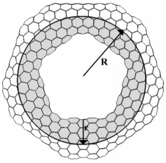
Figure 1.
Structure of nanotorus showing major and minor radii R and r [18]. Reprinted from Journal of Molecular Structure (Theochem), 681, E. Yazgan and E. Taşci and O.B. Malcioğlu and S. Erkoç, Electronic properties of carbon nanotoroidal structures, 231–234, Copyright (2004), with permission from Elsevier.
The larger carbon nanotori were discovered in laser vaporisation [7] and thermal decomposition [19] experiments of single-walled carbon nanotubes as shown in Figure 2. Typically, the major radii of observed carbon nanotori range between 150 and 250 nm, while the minor radii are approximately 2–4 nm. These ring structures might be envisaged as curved carbon nanotubes formed by experimental methods, that are bent in such as manner that their open ends are seamlessly connected together. Such a process is kinetically controlled by the ultrasonic irradiation of nanotubes, and the ring structures obtained are stabilised through van der Waals interactions [20,21]. The key condition for the stability of these configurations is that their strain energy must not exceed the binding energy [22], so that the small carbon nanotori with major radius less than 100 nm do not arise from this technique according to the elasticity of the carbon nanotubes [23].
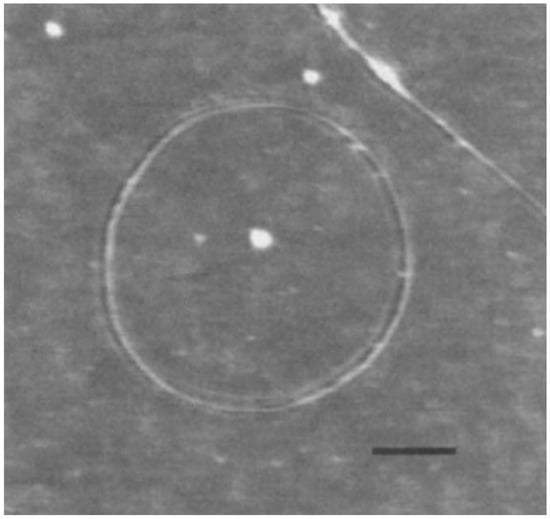
Figure 2.
Experimentally determined carbon nanotorus [7]. Reprinted by permission from Springer Nature: Nature (Fullerene ‘crop circles’, J. Liu and H. Dai and J. H. Hafner and D. T. Colbert and R. E. Smalley, 1997).
However, smaller carbon nanotori and in particular those with major radii much smaller than 100 nm can at least theoretically be fabricated by introducing a pentagon-heptagon pair into the graphitic honeycomb networks of two carbon nanotubes [24,25]. The two carbon nanotubes need not be of the same type; for example one might be zigzag and the other tube armchair. In this method, the bend angle between two segments of the two different tubes is approximately 30, meaning that such 12 segments of carbon nanotubes are needed to construct a closed toroidal molecule. Experimentally, the bend angle is more likely to be 36 due to strain relaxation around the joints [26], and as a result, only 10 equal segments are required to complete a ring structure. In this event, the condition that each segment of carbon nanotubes be of the same length might be relaxed. In this way, a wide variety of carbon nanotori can be constructed by connecting segments of carbon nanotubes of different lengths, bend angles and types [27,28]. Figure 3 presents examples of such a construction.
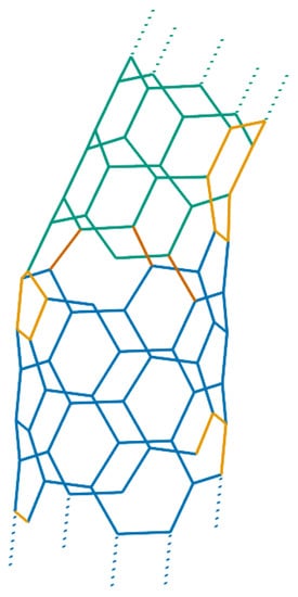
Figure 3.
Carbon nanotori constructed from joining and nanotubes.
Carbon nanotori can also be produced by other modelling techniques, such as constructing from fullerenes using the Goldberg’s prescription [29,30], sewing the walls of single-walled [31,32,33], double-walled [34] or triple-walled [35] carbon nanotubes at both ends and fabricating from only pentagon and heptagon networks [36].
3. Lennard-Jones Potential and Continuum Approximation
The main interaction energy between two non-bonded atoms originates from the van der Waals interaction energy which is modelled by the Lennard-Jones potential function [37], namely
where is the distance between the two particular atoms, and are the potential well depth and the van der Waals radius, respectively, and and denote the attractive and repulsive Lennard-Jones constants, respectively.
For two non-bonded molecules, such as two carbon nanostructures, the total interaction energy can be evaluated by summing the interaction energies between each atom pair of the two molecules, so that we have
where the two molecules are assumed to consist of N and M atoms, and the subscripts represent the types of each atomic interaction. For two non-identical atomic interactions, the appropriate Lennard-Jones constants are conventionally evaluated using the mixing rules [38].
Figure 4 shows the interaction energy between two carbon atoms for any separation distance obtained from the Lennard-Jones potential. Although the energy is a scalar quantity, its sign represents the type of the interaction, where the plus sign denotes a repulsive energy while the minus sign signifies an attractive interaction. We observe that when the distance between the two atoms is small, the repulsive part dominates the attractive one, and when this distance reaches a certain value, the attractive component overtakes the repulsive interaction.
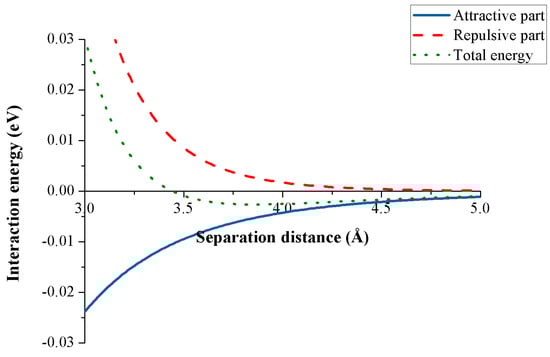
Figure 4.
Lennard-Jones potential for two carbon atoms.
The continuum approximation [39] assumes that all atoms are uniformly distributed over their own structure, and the interaction energy between two molecules as defined by Equation (1) can be approximated by
where for are the average atomic densities for molecule i and the integrals for and 6 are defined by
where denotes the distance between atoms for a typical atomic pair and for denotes the surface elements for each molecule i.
4. Mathematical and Theoretical Framework for Interaction Energy of Nanotorus with Other Nanostructures
In this section, the energy expression as defined in (3) may be evaluated for a number of different molecular configurations and the resulting formulae are summarised in the following sections, and when evaluated, can be substituted into Equation (2) to obtain the total interaction energy. The major advantage of the approach described here is that the analytical expressions so obtained can be readily evaluated using standard algebraic packages, such as MATLAB and MAPLE, and accordingly numerous molecular configurations can be investigated for a low computational effort.
4.1. Interaction Energy of Point and Torus
We first formulate a mathematical model to determine the interaction energy for an atomic point and a torus by using the continuum approximation approach. In the model, a torus with respective major and minor radii R and r is assumed to be centred at the origin of a Cartesian coordinate system , and that the atom is located above the origin at a distance as shown in Figure 5. We comment that the point-torus interaction is useful because the result is needed in order to evaluate the interaction energy of a torus with other nanostructures.
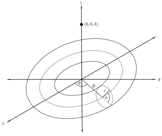
Figure 5.
Schematic showing atom located on central axis of nanotorus.
By utilising the toroidal coordinates as given in (7), the distance between the point and an arbitrary point on the toroidal surface may be expressed as
On substitution of the expression into Equation (3) and integrating over the toroidal surface, we obtain the energy expression for a point and a torus, denoted by , namely
where is the Legendre polynomial of the first kind, and we refer the reader to [40] for the full calculation. Finally, the total interaction energy of an atomic point and a torus, denoted by , is obtained by substituting the into (3), namely
where denotes the mean atomic density of the torus and the integrals are as given in (4).
4.2. Interaction Energy of Sphere Encapsulated Inside Torus
To evaluate the interaction energy of a sphere symmetrically encapsulated inside a torus, it is helpful to first focus only on the interaction energy between a point and a sphere, and then we allow the point to be an arbitrary point on the toroidal surface. Assuming that the centre of the sphere of radius a is located at the origin and the atomic point is situated along the axis at a distance , we can parameterise any position on the spherical surface as
where and are polar and azimuthal angles measured counterclockwise from the x-axis and the -plane, respectively, as shown in Figure 6.
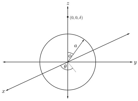
Figure 6.
Schematic showing fullerene of radius a and atom located of a distance apart.
The energy expression for an atom and a fullerene, denoted by , can be deduced as follows [41]
where is the Chebyshev polynomial of the second kind, and further details of the calculation can be found in [42]. Subsequently, the arbitrary point in Figure 6 can range over the toroidal surface.
Assuming that the torus has minor and major radii r and R, respectively, and translating the centre of the sphere to be situated along the central ring inside the torus as illustrated in Figure 7, we can parameterise any position of the point on the toroidal surface by
In this case, the distance is no longer a constant, but varies depending on the position of the arbitrary point on the toroidal surface. We now introduce a new distance parameter which may be expressed as
and on substituting into Equation (6) and performing an integration over the toroidal surface, we may deduce
where is the Chebyshev polynomial of the second kind and
and we refer the reader to the original paper [42] for further details of these calculations. Finally, the total interaction energy for a sphere encapsulated inside a torus, denoted by , can be obtained as
where and are the mean atomic surface densities for the sphere and the torus, respectively, and for are defined in (8). Although clearly complicated, these expressions can nevertheless be readily evaluated with the aid of standard algebraic packages, such as MATLAB and MAPLE.
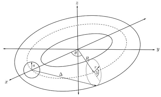
Figure 7.
Schematic showing fullerene encapsulated inside nanotorus.
4.3. Interaction Energy of Sphere and Nanotorus
By relaxing the position of the sphere in the previous section, we may derive a mathematical expression for the interaction energy of a sphere and torus, where the sphere is assumed to be located at any position on the -plane as shown in Figure 8. We can calculate such an interaction energy by performing a similar procedure to that described in the previous section. We have to calculate a new distance parameter, substitute it into Equation (6) and then integrate over the toroidal surface. From Figure 8 and the toroidal transformation as given in (7), we have the alternative distance parameter given by
where and are the offsets in the x- and z-directions. The energy expression between a fullerene and a nanotorus, denoted by , can be expressed as
where and . Using the summation representation of the Chebyshev polynomials of the second kind gives
where , for and , are given by
noting that is the beta function and the final functions and their full derivation can be found in [43]. Finally, we may substitute the resulting expression to (2) to have the total interaction energy for a fullerene and a nanotorus, denoted by , namely
where and are the mean atomic densities for the sphere and the torus, respectively, and integrals for are defined in (10).
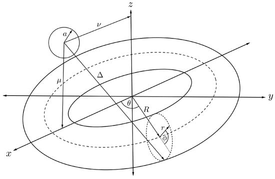
Figure 8.
Schematic showing symmetrically located fullerene and nanotorus.
4.4. Interaction Energy of Two Tori
The interaction energy between two nanotori can be derived using the result of that presented in Section 5 by integrating over the toroidal surface, and the arbitrary point in the previous case becomes an arbitrary point over the surface of another torus as shown in Figure 9. The second torus is assumed to have major and minor radii S and s, respectively, and the polar and azimuthal angles are donated by and , respectively, so that we can parameterise the second torus with Cartesian coordinates,
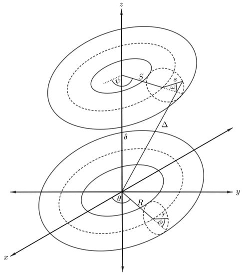
Figure 9.
Schematic showing two symmetrically situated nanotori.
Again in this case, the distance between an arbitrary point and the centre of the torus varies according to the position of the point over the new toroidal surface. The new distance, denoted by , becomes
where . After substituting the new distance into Equation (4), the interaction for the two nanotori, denoted by , can be obtained as
where for and are defined by
and for and 2 are defined by
where and , if we further assume that the major radius R is much larger than the minor radius r. Finally, substituting this result into Equations (13) and (12), respectively, leads to the complete energy expression for the two tori interaction, namely
where denotes the mean atomic density of the torus, are given in (12) and full details of the calculation can be found in [44].
4.5. Interaction Energy of Cylinder and Torus
We assume that the central axis of a cylindrical nanotube of radius a and length is located along the central cavity of a nanotorus, where the middle of the nanotube is situated at the origin and the toroidal plane at a distance Z as shown in Figure 10. We then use the two sets of parametric Cartesian coordinates,
and
as representing two arbitrary points on the nanotube and the nanotorus, respectively. Therefore, the total distance between two particular points over these two interacting molecules is obtained as
where and . By substituting it into (3) and integrating over the cylindrical and toroidal surfaces, we obtain the interaction energy for a nanotube and a torus, denoted by , namely
where and are the respective mean atomic densities for a nanotube and a nanotorus, A and B are the Lennard-Jones constants, is the associated Legendre polynomial of the first kind, and and are respectively defined as follows
and we refer the reader to the original paper [45] for further details concerning the derivation.
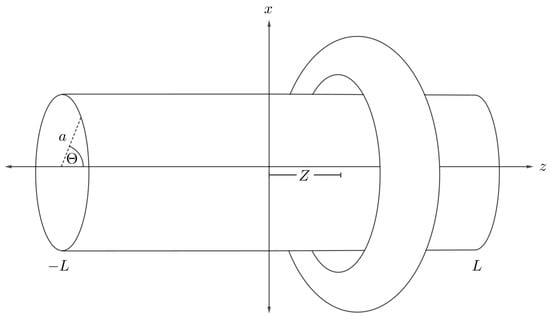
Figure 10.
Schematic showing nanotube and symmetrically situated nanotorus.
4.6. Interaction Energy of Offset Molecule and Torus
To calculate the interaction energy between an offset atom inside a carbon nanotorus, the atom is assumed to be located inside the nanotorus at a distance from the cross-sectional centre of the torus as illustrated in Figure 11. Therefore, this point has Cartesian coordinates
and the torus is parameterised by the toroidal coordinated defined in (7), so the distance between the point and an arbitrary point on the toroidal surface is
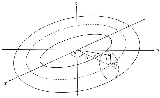
Figure 11.
Schematic showing offset atom within nanotorus.
Substituting into (3) and (2) results in the interaction energy between an offset atom and a torus, denoted by , which is expressible as
For the interaction energy between a torus and an offset fullerene of radius a and offset distance from the cross-sectional centre of the torus as shown in Figure 12. Such an interaction can be evaluated using the same technique as previously described. Finally, the interaction energy of an offset and a torus, denoted by , is derived as
where , and are the mean atomic densities for the fullerene and the torus, is the Appell hypergeometric function of the first kind and the full derivation of (17) is detailed in [46].
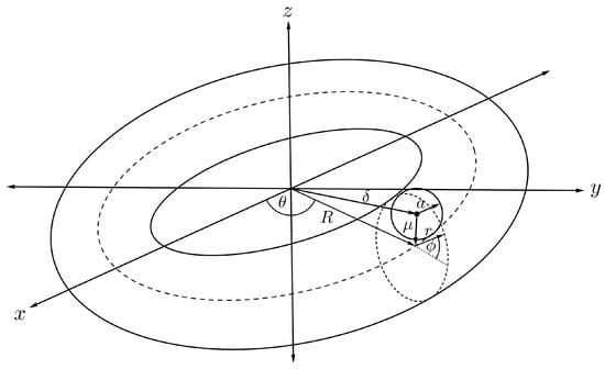
Figure 12.
Schematic showing offset fullerene and nanotorus.
5. Physical Roles, Properties and Applications
Carbon nanotori possess similar physical properties to those of other carbon nanostructures, such as high thermal conductivity and high tensile strength [47,48]. They are resistant to heat up to 4500 K before their structures start to deform [49], and their tensile strength ranges from 5.72–8.52 GPa [50]. However, these properties are dependent on their geometry and the method of their construction. The major and minor radii, representing the ring radius and the tube radius respectively, strongly influence the mechanical properties of the structures including deformation, vibration and buckling [51]. Nanotori with small radii are highly strained under bending loads [52]. the geometric parameters also play a critical role in the applications of carbon nanotori in electricity and magnetism as described in the following subsections.
5.1. Electronic Properties
Electrical properties of carbon nanotori can be classified into three categories depending on the energy gap between the highest occupied molecular orbital (HOMO) and the lowest unoccupied molecular orbital (LUMO). For those obtained by experimental techniques, the classification can be simplified with the following rules. Given as the components of the chiral vector C and as the components of the transverse vector T on a graphene sheet as displayed in Figure 13, the carbon nanotori have metallic characteristics if the values of and are both divisible by three. If only the difference is divisible by three, they are semiconductor tori, while the nanotori are insulator tori if only is divisible by three, otherwise they do not exist [53].
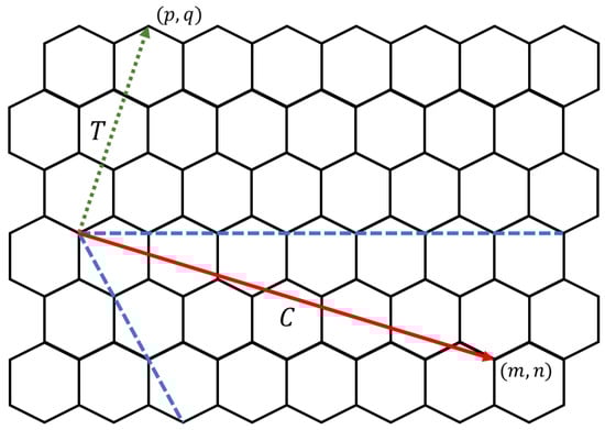
Figure 13.
Chiral (solid) and transverse (dotted) vectors.
The deformation of the carbon nanotube occurring in the bending construction also affects the electronic properties of the resulting carbon nanotori. Localised deformations lead to a dramatic reduction in the electrical conductance, while delocalised deformations only slightly lower the conductance [54]. Deformations also play an important role in the energy gap between HOMO and LUMO. As the size of the carbon nanotori increases, the oscillation fluctuates more wildly in the energy gap and converges to that of the corresponding infinite nanotube when the size is sufficiently large [55]. Further, the electronic features of the carbon nanotori can be altered depending upon the external electric and magnetic fields [56].
For those carbon nanotori with pentagon-heptagon pairs, the energy gap between HOMO and LUMO may be calculated using the extended-Hückel calculations and the tight binding approach. The density of states distribution shows that the number of mobile electrons is directly proportional to the number of carbon atoms of the tori. In addition, the charge density distribution in the interior cavity of the larger carbon nanotori is less than that of the smaller tori, implying an almost charge free region (white area) inside the larger carbon nanotori which may be used for encapsulation applications [57,58]. Figure 14 shows the charge distributions of typical carbon nanotori C, C, C, C and C which possess five-fold symmetry [18].
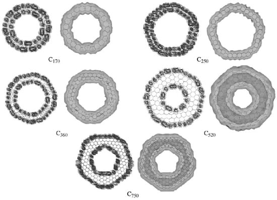
Figure 14.
Charge distributions of carbon nanotori C, C, C, C and C obtained from [18]. Reprinted from Journal of Molecular Structure (Theochem), 681, E. Yazgan and E. Taşci and O.B. Malcioğlu and S. Erkoç, Electronic properties of carbon nanotoroidal structures, 231–234, Copyright (2004), with permission from Elsevier.
5.2. Magnetic Properties
The magnetic properties of carbon nanotori are strongly dependent upon their size, curvature, symmetry and any defects [59,60]. Typically, they have strong magnetic moments which are 130 times larger than those of the benzene molecule [61]. In the absence of the magnetic flux, the metallic nanotori exhibit paramagnetism, while the semiconducting tori show diamagnetism. The induced magnetic moments are independent of the minor radius of the nanotori, but inversely proportional to the major radius [62,63]. Moreover, the magnitude of the moments decreases with increasing temperature as shown in Figure 15 [64].
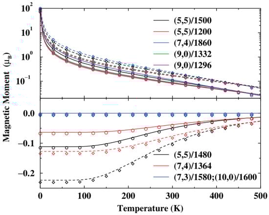
Figure 15.
Relation between induced magnetic moment and temperature for various carbon nanotori in a perpendicular magnetic field of 0.1 T (solid) and 0.2 T (dashed) obtained from [64]. Reprinted figure with permission from L. Liu and G.Y. Guo and C.S. Jayanthi and S.Y. Wu, Colossal paramagnetic moments in metallic carbon nanotori, 88, 217206 (2002). Copyright (2019) by the American Physical Society.
Persistent currents can be generated by introducing a magnetic flux through the carbon nanotori. Such currents originate from the electronic orbital motion and are periodical linear functions of the magnetic flux. The currents are strongly dependent upon the chiral angle of the chiral vector arising from the graphene sheet construction, and become stronger as the angle approaches [65]. Further, the tube-ring interactions from the nanotori encapsulated with a carbon nanotube inside also induces a charge transfer between the interior cavity of the carbon nanotori [66]. However, the persistent currents in the carbon nanotori are diminished as the temperature increases due to the Fermi energy at the charge neutrality point [67].
Carbon nanotori also possess high magnetic resistance which depends upon the strength and the number of the dephasing collisions of electrons inside. However, their magnetic resistance decreases with increasing magnetic field [68].
5.3. Some Potential Applications
Due to the strong attractive energy, carbon nanotori might be used as traps for both charged and uncharged atoms, and the key factors controlling the trap performance are the major and minor radii of the nanotori. The simulation results show that the optimal major radius that provides the strongest attraction is linearly proportional to the minor radius [69]. Further, the minimum energy of the carbon nanotori and the ions can be expressed in terms of the van der Waals parameters for the specific atomic types [40]. Figure 16 illustrates the energy profiles for numerous atoms and ions along the central axis of a nanotorus.
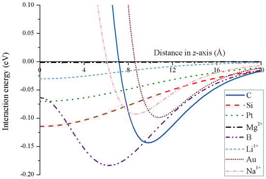
Figure 16.
Energy profiles for various atoms and ions interacting with nanotorus.
Carbon nanotori can also serve as the host to encapsulate carbon atomic chains. The interaction energy between the carbon nanotori and the carbon chain suggest that the chain prefers to remain inside the interior cavity of the nanotori, and the major and minor radii play a critical role in the encapsulation. Especially, the minor radius should be greater than nm, while the nanotori with major radii greater than nm and minor radii around nm provide the optimal configurations for carbon chain encapsulation [70].
In addition, carbon nanotori can encapsulate chains of metallic atoms, such as iron (Fe), copper (Cu) and gold (Au). By introducing the metallic chains into the nanotori with a scanning tunnelling microscope, the composite nanotori show some novel magnetic features. The carbon nanotori encapsulating Fe, Cu and Au chains provide positive, neutral and negative magnetic moments, respectively, and all three metal chains are linearly stable at zero temperature [71].
Further, carbon nanotori may be viewed as components of nano-scaled gigahertz oscillators. By placing a carbon nanotube situated inside the central cavity of the nanotori, the interaction with the nanotube produces a pulse-like force acting at either end of the nanotube, so that the carbon nanotori are sucked by the van der Waals interaction onto the exterior of the carbon nanotube and will oscillate back and forth along the nanotube with frequency of the oscillatory motion in the megahertz range [45].
Other interesting applications of carbon nanotori arise from their charge free interior cavities, which have been proposed as regions to encapsulate nanostructures. If the major and minor radii are sufficiently large, their interaction energy induces an oscillatory motion of the encapsulated nanoparticle within the closed loop of the carbon nanotori. Such motions can generate gigahertz frequencies, such that the minor radius is inversely proportional to the frequency of the oscillation [46,72].
6. Conclusions
In this paper, we have presented a review of the geometry, construction, physical roles and applications of carbon nanotori. Carbon nanotori may be constructed by a variety of experimental methods, and they can be modelled by joining various carbon nanotube segments, perhaps involving different bend angles. Nanotori structures exhibit many promising physical properties which are similar to those of other carbon nanostructures, and especially those relating to mechanical and electrical properties. For several scenarios, we have summarised the known expressions for the interaction energy between carbon nanotori and various other nanostructures. These formulae have been derived using the continuum approximation and assuming the Lennard-Jones potential, and such analytical expressions can be used to readily visualise the interaction energy landscape or to determine the most stable configuration of two molecules. Improving our understanding of the physical properties of carbon nanotori and providing effective tools for modelling their energy behaviour, will inevitably lead to many beneficial future developments in nano and biotechnology for carbon nanotori applications.
Author Contributions
All authors contributed equally to all aspects of the writing of the paper.
Funding
This research was funded by the Royal Golden Jubilee PhD Program (Grant No. PHD/0075/2559), and the Thailand Research Fund (RSA6180076).
Conflicts of Interest
The authors declare no conflict of interest.
References
- Iijima, S. Helical microtubules of graphitic carbon. Nature 1991, 354, 56–58. [Google Scholar] [CrossRef]
- Saito, R.; Dresselhaus, G.; Dresselhaus, M. Physical Properties of Carbon Nanotubes; World Scientific Publishing: Singapore, 1998. [Google Scholar]
- Ray, S.C. Applications of Graphene and Graphene-Oxide Based Nanomaterials; William Andrew: Oxford, UK, 2015. [Google Scholar]
- Bakry, R.; Vallant, R.; Haq, M.; Rainer, M.; Szabo, Z.; Huck, C.; Bonn, G. Medicinal applications of fullerenes. Int. J. Nanomed. 2007, 2, 639–649. [Google Scholar]
- Thamwattana, N.; Hill, J.M. Nanotube bundle oscillators: Carbon and boron nitride nanostructures. Physica B 2009, 404, 3906–3910. [Google Scholar] [CrossRef]
- Karousis, N.; Martinez, I.S.; Ewels, C.P.; Tagmatarchis, N. Structure, properties, functionalization, and applications of carbon nanohorns. Chem. Rev. 2016, 116, 4850–4883. [Google Scholar] [CrossRef] [PubMed]
- Liu, J.; Dai, H.; Hafner, J.H.; Colbert, D.T.; Smalley, R.E. Fullerene ‘crop circles’. Nature 1997, 385, 780–781. [Google Scholar] [CrossRef]
- Geng, J.; Ko, Y.K.; Youn, S.C.; Kim, Y.H.; Kim, S.A.; Jung, D.H.; Jung, H.T. Synthesis of SWNT rings by noncovalent hybridization of porphyrins and single-walled carbon nanotubes. J. Math. Chem. C 2008, 112, 12264–12271. [Google Scholar] [CrossRef]
- Zhou, Z.; Wan, D.; Bai, Y.; Dou, X.; Song, L.; Zhou, W.; Mo, Y.; Xie, S. Ring formation from the direct floating catalytic chemical vapor deposition. Physica E 2006, 33, 24–27. [Google Scholar] [CrossRef]
- Kukushkin, A.B.; Neverov, V.S.; Marusov, N.L.; Semenov, I.B.; Kolbasov, B.N.; Voloshinov, V.V.; Afanasiev, A.P.; Tarasov, A.S.; Stankevich, V.G.; Svechnikov, N.Y. Few-nanometer-wide carbon toroids in the hydrocarbon films deposited in tokamak T-10. Chem. Phys. Lett. 2011, 506, 265–268. [Google Scholar] [CrossRef]
- Natsuki, T.; Tantrakarn, K.; Endo, M. Effects of carbon nanotube structures on mechanical properties. Appl. Phys. A 2004, 79, 117. [Google Scholar] [CrossRef]
- Zhang, X.F.; Zhang, Z. Polygonal spiral of coil-shaped carbon nanotubes. Phys. Rev. B 1995, 52, 5313–5317. [Google Scholar] [CrossRef]
- Dunlap, B.I. Constraints on small graphitic helices. Phys. Rev. B 1994, 50, 5134–8137. [Google Scholar] [CrossRef]
- Ihara, S.; Itoh, S. Helically coiled and toroidal cage forms of grapitic carbon. Carbon 1995, 33, 931–939. [Google Scholar] [CrossRef]
- Feng, C.; Liew, K.M. A molecular mechanics analysis of the buckling behavior of carbon nanorings under tension. Carbon 2009, 47, 3508–3514. [Google Scholar] [CrossRef]
- Liu, L.; Liu, F.; Zhao, J. Curved carbon nanotubes: From unique geometries to novel properties and peculiar applications. Nano Res. 2014, 7, 626–657. [Google Scholar] [CrossRef]
- Rappé, A.K.; Casewit, C.J.; Colwell, K.S.; Goddard, W.A.; Skiff, W.M. UFF, a full periodic table force field for molecular mechanics and molecular dynamics simulations. J. Am. Chem. Soc. 1992, 114, 10024–10035. [Google Scholar] [CrossRef]
- Yazgan, E.; Taşci, E.; Malcioğlu, O.; Erkoç, S. Electronic properties of carbon nanotoroidal structures. J. Mol. Struct. THEOCHEM 2004, 681, 231–234. [Google Scholar] [CrossRef]
- Ahlskog, M.; Seynaeve, E.; Vullers, R.J.M.; Haesendonck, C.V.; Fonseca, A.; Hernadi, K.; Nagy, J.B. Ring formations from catalytically synthesized carbon nanotubes. Chem. Phys. Lett. 1999, 300, 202–206. [Google Scholar] [CrossRef]
- Martel, R.; Shea, H.R.; Avouris, P. Ring formation in single-wall carbon nanotubes. J. Phys. Chem. B 1999, 103, 7551–7556. [Google Scholar] [CrossRef]
- Thess, A.R.; Lee, P.N.; Dai, H.; Petit, P.; Robert, J.; Xu, C.; Lee, Y.H.; Kim, S.G.; Rinzler, A.G.; Colbert, D.T.; et al. Crystalline ropes of metallic carbon nanotubes. Science 1996, 273, 483–487. [Google Scholar] [CrossRef]
- Meunier, V.; Lambin, P.; Lucas, A.A. Atomic and electronic structures of large and small carbon tori. Phys. Rev. B 1998, 57, 14886. [Google Scholar] [CrossRef]
- Chang, I.L.; Chou, J.W. A molecular analysis of carbon nanotori formation. J. Appl. Phys. 2012, 112, 063523. [Google Scholar] [CrossRef]
- Dunlap, B.I. Connecting carbon tubules. Phys. Rev. B 1992, 46, 1933–1936. [Google Scholar] [CrossRef]
- Dunlap, B.I. Relating carbon tubules. Phys. Rev. B 1994, 49, 5643–5650. [Google Scholar] [CrossRef]
- Fonseca, A.; Hernadi, K.; Nagy, J.; Lambin, P.; Lucas, A.A. Model structure of perfectly grapitizable coiled carbon nanotubes. Carbon 1995, 33, 1759–1775. [Google Scholar] [CrossRef]
- Cox, B.J.; Hill, J.M. New carbon molecules in the form of elbow-connected nanotori. J. Phys. Chem. C 2007, 111, 10855–10860. [Google Scholar] [CrossRef]
- Baowan, D.; Cox, B.J.; Hill, J.M. Toroidal molecules formed from three distinct carbon nanotubes. J. Math. Chem. 2008, 44, 515–527. [Google Scholar] [CrossRef]
- Ihara, S.; Itoh, S. Toroidal forms of graphitic carbon. Phys. Rev. B 1993, 47, 12908–12911. [Google Scholar] [CrossRef]
- Itoh, S.; Ihara, S. Toroidal forms of graphitic carbon. II. Elogated tori. Phys. Rev. B 1994, 48, 8323–8328. [Google Scholar] [CrossRef]
- Sano, M.; Kamino, A.; Okamura, J.; Shinkai, S. Ring closure of carbon nanotubes. Science 2001, 293, 1299–1301. [Google Scholar] [CrossRef]
- Guo, A.; Fu, Y.; Guan, L.; Zhang, Z.; Wu, W.; Chen, J.; Shi, Z.; Gu, Z.; Huang, R.; Zhang, X. Spontaneously formed closed rings of single-wall carbon nanotube bundles and their physical mechanism. J. Phys. Chem. C 2007, 111, 3555–3559. [Google Scholar] [CrossRef]
- Komatsu, N.; Shimawaki, T.; Aonuma, S.; Kimura, T. Ultrasonic isolation of toroidal aggregates of single-walled carbon nanotubes. Carbon 2006, 44, 2091–2093. [Google Scholar] [CrossRef]
- Colomer, J.F.; Henrard, L.; Flahaut, E.; Tendeloo, G.V.; Lucas, A.A.; Lambin, P. Rings of double-walled carbon nanotube bundles. Nano Lett. 2003, 3, 685–689. [Google Scholar] [CrossRef]
- Yu, H.; Zhang, Q.; Luo, G.; Wei, F. Rings of triple-walled carbon nanotube bundles. Appl. Phys. Lett. 2006, 89, 223106. [Google Scholar] [CrossRef]
- László, I.; Rassat, A. Toroidal and spherical fullerene-like molecules with only pentagonal and heptagonal faces. Int. J. Quantum Chem. 2001, 84, 136–139. [Google Scholar] [CrossRef]
- Lennard-Jones, J.E. Cohesion. Proc. Phys. Soc. 1931, 43, 461–482. [Google Scholar] [CrossRef]
- Maitland, G.C.; Rigby, M.; Smith, E.B.; Wakeham, W.A. Intermolecular Forces: Their Origin and Determination; Clarendon Press: Oxford, UK, 1981. [Google Scholar]
- Girifalco, L.A.; Hodak, M.; Lee, R.S. Carbon nanotubes, buckyballs, ropes, and a universal graphitic potential. Phys. Rev. B 2000, 62, 13104–13110. [Google Scholar] [CrossRef]
- Sarapat, P.; Hill, J.M.; Baowan, D. Mechanics of atoms interacting with a carbon nanotorus: Optimal configuration and oscillation behaviour. Philos. Mag. 2019, 99, 1386–1399. [Google Scholar] [CrossRef]
- Baowan, D.; Cox, B.J.; Hilder, T.A.; Hill, J.M.; Thamwattana, N. Modelling and Mechanics of Carbon-Based Nanostructured Materials; William Andrew: Oxford, UK, 2017. [Google Scholar]
- Sarapat, P.; Baowan, D.; Hill, J.M. Interaction energy for a fullerene encapsulated in a carbon nanotorus. Z. Angew. Math. Phys. 2018, 69, 77. [Google Scholar] [CrossRef]
- Sarapat, P.; Baowan, D.; Hill, J.M. Equilibrium location for spherical DNA and toroidal cyclodextrin. Appl. Nanosci. 2018, 8, 537–544. [Google Scholar] [CrossRef]
- Sarapat, P.; Hill, J.M.; Baowan, D. Optimal configurations for carbon nanotori. Appl. Nanosci. 2019, 9, 225–232. [Google Scholar] [CrossRef]
- Hilder, T.A.; Hill, J.M. Oscillating carbon nanotori along carbon nanotubes. Phys. Rev. B 2007, 75, 125415. [Google Scholar] [CrossRef]
- Hilder, T.A.; Hill, J.M. Orbiting atoms and C60 fullerenes inside carbon nanotori. J. Appl. Phys. 2007, 101, 064319. [Google Scholar] [CrossRef]
- Yu, M.F.; Lourie, O.; Dyer, M.J.; Moloni, K.; Kelly, T.F.; Ruoff, R.S. Strength and breaking mechanism of multiwalled carbon nanotubes under tensile load. Science 2000, 287, 637–640. [Google Scholar] [CrossRef] [PubMed]
- Wong, E.W.; Sheehan, P.E.; Lieber, C.M. Nanobeam mechnaics: Elasticity, strength and toughness of nanorods and nanotubes. Science 1997, 277, 1971–1975. [Google Scholar] [CrossRef]
- Taşci, E.; Yazgan, E.; Malcioğlu, O.B.; Erkoç, Ş. Stability of carbon nanotori under heat treatment: Molecular- dynamics simulations. Fuller. Nanotub. Carbon Nanostruct. 2006, 13, 147–154. [Google Scholar] [CrossRef]
- Chen, N.; Lusk, M.T.; Duin, A.C.T.; Goddard, W.A. Mechanical properties of connected carbon nanorings via molecular dynamics simulation. Phys. Rev. B 2005, 72, 085416. [Google Scholar] [CrossRef]
- Sun, B. Deformation, vibration, buckling of continuum nanotorus. J. Nanomater. 2010, 67, 480628. [Google Scholar] [CrossRef]
- Çağin, T.; Gao, G.; Goddard, W.A. Computational studies on mechanical properties of carbon nanotori. Turk. J. Phys. 2006, 30, 221–229. [Google Scholar]
- Zhang, Z.; Yang, Z.; Wand, X.; Yuan, J.H.; Zhang, M.Q. The electronic structure of a deformed chiral carbon nanotorus. J. Phys. Condens. Matter. 2005, 17, 249–255. [Google Scholar] [CrossRef]
- Liu, L.; Jayanthi, C.S.; Wu, S.Y. Structural and electronic properties of a carbon nanotorus: Effects of delocalized and localized deformations. Phys. Rev. B 2001, 64, 033412. [Google Scholar] [CrossRef]
- Liu, C.P.; Ding, J.W. Electronic structure of carbon nanotori: The roles of curvature, hybridization, and disorder. J. Phys. Condens. Matter 2006, 18, 4077–4084. [Google Scholar] [CrossRef]
- Latgé, A.; Rocha, C.G.; Wanderley, L.A.L.; Pacheco, M.; Orellana, P.; Barticevic, Z. Defects and external field effects on the electronic properties of a carbon nanotube torus. Phys. Rev. B 2003, 67, 155413. [Google Scholar] [CrossRef]
- Oh, D.H.; Park, J.M.; Kim, K.S. Structures and electronic properties of small carbon nanotube tori. Phys. Rev. B 2000, 62, 1600–1603. [Google Scholar] [CrossRef]
- Wu, X.; Zhou, R.; Yang, J.; Zeng, X.C. Density-functional theory studies of step-kinked carbon nanotubes. J. Phys. Chem. C 2011, 115, 4235–4239. [Google Scholar] [CrossRef]
- Manzo, J.A.R.; Urías, F.L.; Terrones, M.; Terrones, H. Magnetism in corrugated carbon nanotori: The importance of symmetry, defects and negative curvature. Nano Lett. 2004, 4, 2179–2183. [Google Scholar] [CrossRef]
- Liu, C.P.; Chen, H.B.; Ding, J.W. Magnetic response of carbon nanotori: The importance of curvature and disorder. J. Phys. Condens. Matter 2008, 20, 015206. [Google Scholar] [CrossRef]
- Haddon, R.C. Electronic properties of carbon toroids. Nature 1997, 388, 31–32. [Google Scholar] [CrossRef]
- Lin, M.F.; Chuu, D.S. Persistent currents in toroidal carbon nanotubes. Phys. Rev. B 1998, 57, 6731–6737. [Google Scholar] [CrossRef]
- Liu, C.P.; Xu, N. Magnetic response of chiral carbon nanotori: The dependence of torus radius. Physica B 2008, 403, 2884–2887. [Google Scholar] [CrossRef]
- Liu, L.; Guo, G.Y.; Jayanthi, C.S.; Wu, S.Y. Colossal paramagnetic moments in metallic carbon nanotori. Phys. Rev. Lett. 2002, 88, 217206. [Google Scholar] [CrossRef]
- Zhang, Z.; Yuan, J.; Qiu, M.; Peng, J.; Xiao, F. Persistent currents in carbon nanotori: Effects of structure deformations and chirality. J. Appl. Phys. 2006, 99, 104311. [Google Scholar] [CrossRef]
- Tang, X. Persistent current in a carbon nanotube torus encapsulated with a carbon ring. J. Phys. Condens. Matter 2011, 23, 105302. [Google Scholar] [CrossRef]
- Latil, S.; Roche, S.; Rubio, A. Persistent currents in carbon nanotube based rings. Phys. Rev. B 2003, 67, 165420. [Google Scholar] [CrossRef]
- Shea, H.R.; Martel, R.; Avouris, P. Electrical transport in rings of single-wall nanotubes: One-dimensional localization. Phys. Rev. Lett. 2000, 84, 4441. [Google Scholar] [CrossRef]
- Chan, Y.; Cox, B.J.; Hill, J.M. Carbon nanotori as traps for atoms and ions. Physica B 2012, 407, 3479–3483. [Google Scholar] [CrossRef]
- Sumetpipat, K.; Lee, R.K.F.; Cox, B.J.; Hill, J.M.; Baowan, D. Carbon nanotori and nanotubes encapsulating carbon atomic-chains. J. Math. Chem. 2014, 52, 1817–1830. [Google Scholar] [CrossRef]
- Lusk, M.T.; Hamm, N. Toroidal carbon nanotubes with encapsulated atomic metal loops. Phys. Rev. B 2007, 76, 125422. [Google Scholar] [CrossRef]
- Hilder, T.A.; Hill, J.M. Orbiting nanosectors inside carbon nanotori. Nano Lett. 2007, 2, 50–53. [Google Scholar] [CrossRef]


© 2019 by the authors. Licensee MDPI, Basel, Switzerland. This article is an open access article distributed under the terms and conditions of the Creative Commons Attribution (CC BY) license (http://creativecommons.org/licenses/by/4.0/).