Abstract
In recent years, the constant-envelope orthogonal frequency-division multiplexing (CE-OFDM) has been considered as a candidate waveform in broadband satellite systems as it has a 0-dB peak-to-average power ratio (PAPR). However, the carrier frequency offset (CFO) estimation scheme for CE-OFDM broadband satellite systems directly affects system performance. In this paper, we analyze the network architecture and the propagation environment of CE-OFDM broadband satellite systems, and we propose a data-aided CFO estimation strategy based on the frequency domain pilot symbols. The Cramer–Rao bound (CRB) of our CFO estimator is given by mathematical analysis, and the effect of the number of pilot symbols on the estimation performance is analyzed. The pilot symbol-based CFO estimator is composed of a phase demodulator and a discrete Fourier transform (DFT) module, and it can obtain a large estimation range under a small pilot overhead. The simulation results show that the CE-OFDM broadband satellite systems can achieve a good bit error rate (BER) performance by using the proposed strategy to estimate and compensate the CFO.
1. Introduction
With the development of information technology, the space-air-ground integrated network (SAGIN) has received extensive attention. The most touted advantage of the SAGIN is its ability to enable communication anytime, anywhere. The space network of SAGIN is composed of various satellites and constellations (e.g., Geostationary (GEO), Medium Earth Orbit (MEO), and Low Earth Orbit (LEO) satellites), as well as the corresponding terrestrial infrastructures (e.g., gateways and ground stations) [1]. To support emerging applications via satellites, such as high-speed internet access and multimedia services, the high throughput broadband satellite systems have become a research hotspot [2]. Some organizations have already carried out some MEO/LEO constellation plans, such as OneWeb and SpaceX. High operating frequency and wide bandwidth, as well as a high data rate, have become the main features of the next-generation broadband satellite systems [3].
Among the key technologies of the next-generation broadband satellite systems (e.g., mobility management, routing algorithm, etc.), the waveform design of the physics layer is essential as it affects the data rate and the peak-to-average power ratio (PAPR), as well as other system parameters. As a unique form of multicarrier modulation, the orthogonal frequency-division multiplexing (OFDM) waveform is the cornerstone of the fourth-generation (4G) terrestrial wireless systems, and the OFDM-like waveforms have already been adopted in the fifth-generation (5G) New Radio (NR) specification, including both the terrestrial and satellite networks [4]. Therefore, how to use OFDM technology in satellite systems is of great significance.
In order to make OFDM technology available in satellite systems, two main problems need to be solved, which are the high PAPR caused by OFDM itself and the large carrier frequency offset (CFO) caused by the related movement between the satellite and the terminal. Among the various PAPR reduction techniques, the constant-envelope OFDM (CE-OFDM) proposed by Thompson et al. in [5] is considered as an effective method in broadband satellite systems [6]. The 0 dB PAPR signal is obtained by applying a nonlinear phase modulation to a real-valued OFDM signal, while the drawback is that the spectral efficiency is reduced to half that of the regular OFDM signal. Since the power resources are more precious than spectrum resources in broadband satellite systems, CE-OFDM can find important applications. The spectrum efficiency-enhanced transceiver for CE-OFDM [7,8], the CE-OFDM based mm-wave communication system [9], and the iterative space-frequency equalizer for CE-OFDM mm-wave systems [10] have been proposed in recent years, which promote the application of CE-OFDM in broadband satellite systems. However, the large CFO caused by the related movement introduces interference in CE-OFDM systems, and it needs to be estimated and compensated.
The CFO estimation strategies can be grouped into two categories, namely: data-aided estimation strategies—comprising the time domain training sequences [11,12,13], the frequency domain pilot symbols such as the primary synchronization signal (PSS) [14] and the secondary synchronization signal (SSS) [15] designed for the long-term evolution (LTE) network—and blind estimation strategies comprising the kurtosis-type criterion [16], the diagonality criterion [17], and the presence of null subcarriers [18]. Since the data-aided strategies generally have higher estimation accuracy, these strategies are more likely to be used in the communication system than the blind strategies. The time domain training symbol containing two identical halves proposed in [11] can be used to estimate the CFO, but the frequency acquisition range is subcarrier spacing. In order to improve the estimation range, the optimal periodic training signal is discussed in [12,13], and the Cramer-Rao bound (CRB) is derived. However, the drawback of the time domain training signal is the decline of the spectral efficiency.
Since CE-OFDM has sacrificed spectral efficiency in order to achieve 0 dB PAPR, using a time domain training signal for frequency offset estimation will further lead to a decrease in spectral efficiency. Therefore, it is of considerable significance to design the CFO estimation strategy according to the CE-OFDM broadband satellite system requirements (e.g., the range of CFO) and the structure of the CE-OFDM signal itself. A CFO estimation scheme based on the null subcarrier is proposed for the CE-OFDM satellite system under the additive white Gaussian noise (AWGN) channel and multipath fading channel in [19]. However, the channel state information is assumed to be ideally known at the receiver in [19], which is difficult to achieve in the actual system.
In this paper, we proposed a data-aided CFO estimation strategy for CE-OFDM broadband satellite communication systems. The purpose of this paper is to focus only on the estimation of CFO. Therefore, we assume that the timing offset is perfectly compensated at the receiver. The main contributions of this paper are summarized as follows:
(1) We design a pilot symbol structure placed on the frequency domain subcarriers of the CE-OFDM signal, which can be used to estimate the integer and fractional CFO under AWGN and flat fading channel. The CRB of the proposed structure is analyzed by mathematical analysis.
(2) We analyze the effect of the number of pilot symbols on the estimation performance and prove that based on the characteristics of the CE-OFDM signal, only a small overhead is required to obtain good estimation performance.
(3) We propose a low computation complexity CFO estimator named the pilot symbol-based CFO estimator (PSCE), which is composed of a phase demodulator and a discrete Fourier transform (DFT) module. The estimation performances under different CFOs are evaluated under an LTE-like frame structure. The simulation results show that the PSCE is susceptible to the well-known threshold effect caused by the phase demodulator at a low carrier-to-noise ratio (CNR), and the PSCE is accurate in the moderate and high CNR region.
The rest of this paper is organized as follows. Section 2 presents the broadband satellite system architecture and the propagation environment, including both the CFO and the channel fading. Section 3 shows the CE-OFDM transceiver structure and analyzes the impact of the CFO. Section 4 presents the proposed pilot symbol structure. Section 5 describes the PSCE and the CRB. Section 6 shows the simulation results. Section 7 concludes the paper.
2. Broadband Satellite System Architecture and Propagation Environment
A broadband satellite communication system has the advantages of a high data transmission rate and the support for a large number of user terminals. According to [20], the broadband satellite system architecture includes the satellites, the forward link transmission unit (FL-TU) and the return link reception unit (RL-RU) with a gateway (GW) to the external terrestrial networks, and the satellite terminals (ST) that can receive the satellite signals and convert them to signals (e.g., Wi-Fi) available for user terminals (UT). Figure 1 describes the broadband satellite system architecture.
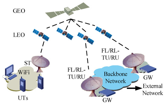
Figure 1.
Broadband satellite system architecture.
In Table 1, the slices of available spectrum for broadband satellite communication services are listed. It can be seen that the broadband satellite systems have more abundant spectrum resources than the traditional L/S band satellite systems. However, one of the disadvantages of using high operating frequencies is a significant path loss. In order to achieve high antenna gain to combat the significant path loss, the antennas of ST and TU/RU are generally required to point directly to the satellite. As people are more willing to access the terrestrial network in the urban environment, satellite communications are generally used in rural areas. Therefore, in this paper, the channel is considered as a flat fading, which is dominated by the light of sight (LOS) path.

Table 1.
Available spectrum for broadband satellite communication services.
Another disadvantage of the high operating frequency is the large CFO. In satellite systems, the CFO consists of two main parts: the phase noise caused by the non-ideal oscillator, and the Doppler frequency offset caused by the high speed related movement between the satellite and the terminal. The detailed analysis of the phase noise and the effect of phase noise on the CE-OFDM signal can be found in [21] and [22], respectively. The conclusion is that the phase noise will interfere with the CE-OFDM signal in the form of additive noise, resulting in the degradation of bit error rate (BER) performance. The effect of Doppler frequency offset to the CE-OFDM signal is presented in [19]. The author in [19] shows that the range of normalized Doppler frequency offset in the LEO system is about , which is normalized to the carrier frequency. The maximum Doppler frequency offset will be kHz to kHz with the operating frequency changing from a Ka-band to a W-band. Therefore, the CFO estimation strategy needs to support a large estimation range. In this paper, we assume that the non-ideal factors in the propagation environment include the Doppler frequency offset and the phase noise, as well as the flat fading channel, and we leave the estimation of the phase noise and the channel for further study.
The notations used in this paper are defined as follows. We use superscripts to denote the conjugate, the transpose, and the conjugate transpose, respectively. The bold-faced, small letter is a vector, and the capital letter is the matrix. and represent the identity matrix and the zero matrix of dimension , respectively. is the entry in row i and column j of . is the diagonal matrix. and denote the real part and the imaginary part of a complex value, respectively. The determination of is and the modulo operator is .
3. CE-OFDM Transceiver Structure and the Impact of CFO
The difference between the CE-OFDM system and the OFDM system is that the CE-OFDM system adjusts the symbol structure before the inverse discrete Fourier transform (IDFT) through the conjugate symmetric mapping module so that the result of the IDFT is a real-valued sequence, and then the real-valued sequence is modulated by the phase modulation module. The detailed description of the CE-OFDM transceiver structure can be found in [5], and we give a brief review here.
Figure 2 shows the CE-OFDM transceiver structure. Modulation symbols are sent to the conjugate symmetry mapping module, and the output is conjugated symmetric sequence as:
where is the input modulation symbols in the frequency domain, is the length of the useful symbols, and is the length of the row vector comprised of zeros. Therefore, the spectrum efficiency of the CE-OFDM signal is reduced to half that of the regular OFDM signal. The CE-OFDM signal can be expressed as , where , . is the modulation index, is the IDFT of , N is the IDFT point, and is the length of a cyclic prefix (CP).
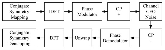
Figure 2.
Constant-envelope orthogonal frequency-division multiplexing (CE-OFDM) transceiver structure.
is the time domain signal finally transmitted by the CE-OFDM transmitter. It can be seen that the is obtained by applying a nonlinear phase modulation to the . Since is the IDFT of the , and has a conjugate symmetry structure, is a real-valued OFDM signal. Thus, the envelope of the CE-OFDM signal is a fixed value and the PAPR of the CE-OFDM signal is 0 dB.
As the signal passes through the flat fading channel with CFO, the received signal is
where represents the channel fading factor, is the signal amplitude with channel attenuation, is the normalized Doppler frequency offset, is the phase noise, and is the additive noise (). We assume that the timing offset is perfectly compensated at the receiver. Therefore, there is only frequency offset and phase noise in Equation (2).
The phase information obtained after the phase demodulator is
where is the noise component after the phase demodulator. From Equation (3), we can see that the Doppler frequency offset component and the phase noise component are added to the , and this will cause interference after the DFT module, causing the symbol to be demodulated incorrectly.
The phase diagram of the received signal is given in Figure 3. It was proven in [5] that any fixed phase offset does not affect the BER performance. Therefore, only the CFO components need to be estimated and compensated. In this paper, we assume that the phase noise is ideally compensated at the receiver, and we concentrate on the estimation of . In the following text, and are combined with for simplicity.
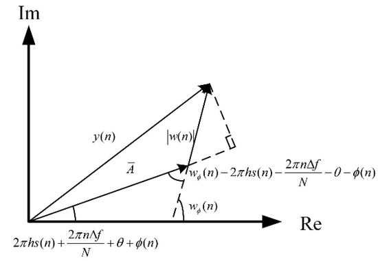
Figure 3.
Phase diagram of the received signal.
4. Pilot Symbol Structure
In order to obtain the frequency domain signal, we performed the DFT transform on Equation (3). The result is
where and are the DFT of and , respectively.
From Equation (4), it can be seen that there is an additive relationship between the , the , and the modulation symbols . Therefore, if the pilot symbols are inserted into the frequency domain subcarriers at the transmitter, these symbols can be used to estimate the through the PSCE. In this section, we propose the optimal pilot symbol structure.
Similar to the LTE system, the resources in the CE-OFDM system can be divided into time–frequency resource blocks, which are shown in Figure 4. It can be seen from Figure 4 that for each time domain symbol , the frequency domain symbols are placed symmetrically concerning the direct current (DC) subcarrier, and the zero-filling high-frequency subcarriers are used to achieve oversampling gain (like LTE).
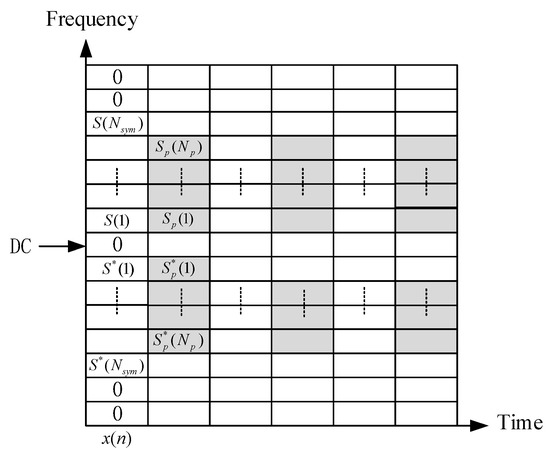
Figure 4.
Pilot symbol structure.
The workflow of the proposed optimal pilot symbol structure is illustrated as follows.
| Procedure 1 Workflow of the proposed optimal pilot symbol structure |
| Transmitter processing flow: 1: Calculate the carrier frequency offset in the communication scenario based on the speed of motion of the satellite and the terminal. 2: Determine the pilot symbol overhead and the pilot symbol placement interval according to the accuracy requirements of the frequency offset estimation. 3: Place the frequency domain pilot symbols symmetrically on both sides of the DC subcarrier. It should be noted that the pilot symbols should be placed on the low-frequency subcarriers. 4: Place the useful symbols symmetrically on the remaining symbols, and then the is obtained. 5: Get the by doing IDFT on the . 6: After the phase modulation of , the is obtained. Receiver processing flow: 1: The received signal is sent to the PSCE module. The is obtained by doing the phase demodulation and the DFT operations. 2: Calculate the and according to the method in Section 5. 3: The estimation of CFO is . 4: Use the to compensate the received signal as . 5: The compensated signal is sent to the DFT module to obtain useful symbols. |
In the next section, we will present the PSCE and prove that the proposed pilot symbol structure has the optimal estimation accuracy through the analysis of CRB.
5. Pilot Symbol-Based CFO Estimator and the CRB
The structure of the PSCE includes a phase demodulator, a phase unwrap module, and a DFT module, and it is shown in Figure 5. The difference with [19] is that the CFO is estimated based on the entire pilot symbols instead of a single null subcarrier. We will prove that this can improve the estimation accuracy. According to the analysis above, the output of DFT is (Equation (4)). If the pilot symbols are inserted at the transmitter, then Equation (4) can be rewritten as (5), where .
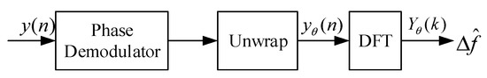
Figure 5.
The structure of pilot symbol-based CFO estimator (PSCE).
The linear relationship between the and the as well as the can be expressed as
where , , and are:
It can be seen from Equation (6) that can be estimated by a minimum variance unbiased (MVU) estimator according to the theory in [23]. The MVU estimator of and the corresponding CRB can be obtained as (8) and (9), respectively:
where is the variance of . Similar to [19], the ideal estimation range of is , which is half the size of IDFT. After some simplifications, we obtain
Therefore, the purpose of the pilot symbol placement is to minimize the CRB, which is equal to the maximum value of . The relationship between the value of and the frequency position of the pilot symbol is shown in Figure 6. If a pilot symbol is inserted at the transmitter, the corresponding value of and can be obtained (e.g., insert to obtain and ), which corresponds to the real and the imaginary coefficients of this pilot symbol. The value of can be obtained through mathematical analysis:
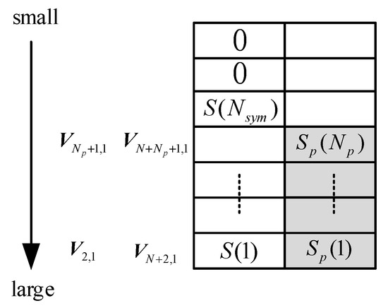
Figure 6.
The relationship between the value of and the frequency position of the pilot symbol.
From Figure 6 and Equation (11), we can get the conclusion that the pilot symbols should be placed symmetrically concerning the DC subcarrier to minimize the CRB. This conclusion proves that the proposed pilot symbol structure has optimal estimation performance.
6. Simulation Results and Analysis
The one-sided phase noise masks in [19] were used in the simulation. Table 2 shows these masks. We used the mean squared error (MSE) and the BER to evaluate the estimation performance. The MSE is defined as , where is the simulation frames per CNR. The simulation parameters are given in Table 3. Since we focused on the CFO estimation performance when we simulated the BER performance, the phase noise was assumed to be known at the receiver and was compensated after the CFO compensation. In order to compare with the existing CFO estimation scheme, the Minn algorithm in [12], the maximum likelihood (ML) algorithm in [24], and the decision feedback estimator (DFE) in [25] were chosen as the comparison schemes. The CRB of PSCE was compared with the Cramer-Rao lower bound (CRLB) in [12].
Table 2.
Aggregate phase noise masks (dBc/Hz).
Table 3.
Simulation parameters.
Figure 7 shows the MSE performance of the PSCE under different CFOs and pilot overheads when the modulation index of the CE-OFDM signal was 0.8. It can be seen that the threshold effect exists at a low CNR. As the maximum Doppler frequency offset was kHz to kHz with the operating frequency changing from the Ka-band to W-band, the normalized CFO was set as 0.5 and 80.5. When was 0.5, the threshold was about 10 dB. When was 80.5, the threshold was about 12 dB. It can be seen that when the CNR was greater than the threshold and was 31, the MSE performance of PSCE was better than that of the DFE algorithm. Therefore, adapting the frequency offset estimation algorithm to the characteristics of the CE-OFDM system can improve the estimation performance.
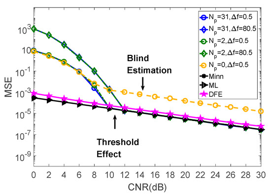
Figure 7.
The mean squared error (MSE) performance of PSCE.
Furthermore, when the CNR was greater than the threshold and was 31, the MSE performance of PSCE was better than that of the Minn algorithm and was almost equal to that of the ML algorithm. At this time, the pilot overhead was the same as the Minn algorithm and the ML algorithm. When was 2, the gap between the PSCE and the Minn algorithms as well as the ML algorithm was less than 1 dB, but the pilot overhead of PSCE was only two frequency domain symbols, which was far less than the other algorithms. When was 0, the PSCE was transformed into a blind estimator, and its MSE performance was limited.
Figure 8 shows the CRB of PSCE under different pilot overheads. When was 31, the CRB of PSCE coincided with the CRLB, which proves that the CFO estimator is the MVU estimator. When the pilot overhead was reduced, the CRB of the proposed algorithm gradually increased. Figure 9 shows the BER performance of PSCE. Except for the blind estimation case ( is 0) when the CFO was equal to 0.5 or 80.5, the corresponding BER performance curve coincided with the ideal BER performance curve. Therefore, the PSCE can effectively reduce the pilot overhead while ensuring the BER performance.
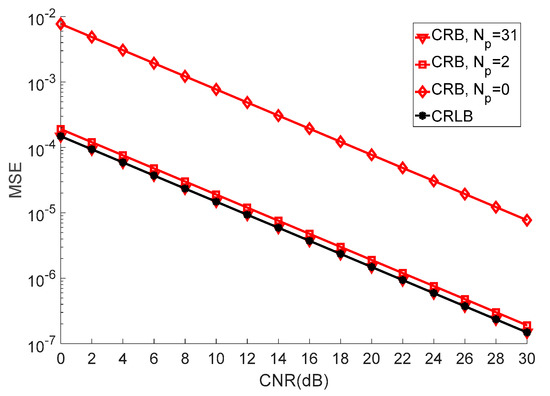
Figure 8.
The Cramer-Rao bound (CRB) of PSCE.
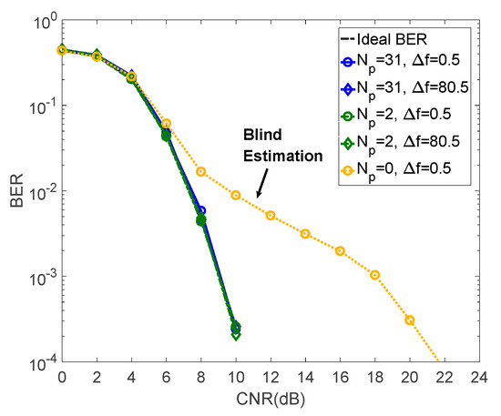
Figure 9.
The bit error rate (BER) performance of PSCE ().
Figure 10 shows the MSE performance of PSCE under different modulation indices when was 31. It can be seen that the estimation performance of PSCE was not affected by the value of the modulation index. Figure 11 shows the BER performance of PSCE under different modulation indices when was 31. The BER performance of PSCE with different CFOs and modulation techniques is shown in Figure 12. The PSCE can achieve good BER performance under different modulation indices and techniques.
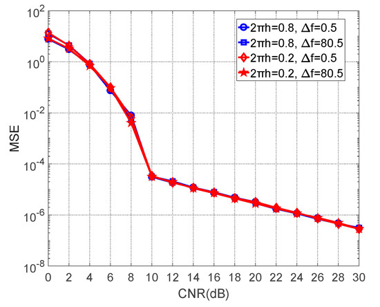
Figure 10.
The MSE performance of PSCE under different modulation indices (, ).
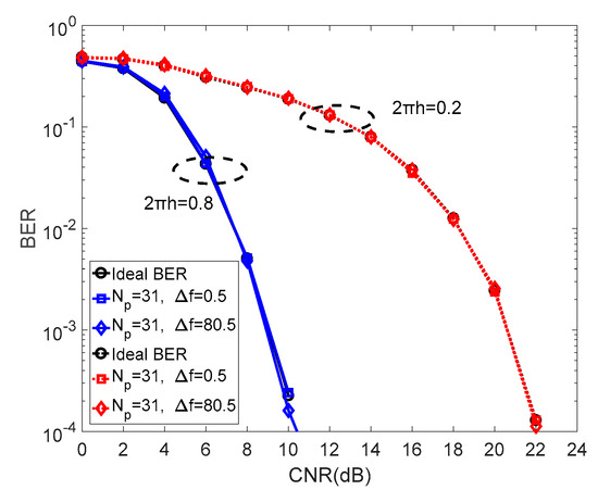
Figure 11.
The BER performance of PSCE under different modulation indices (, ).
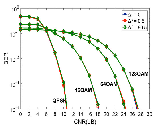
Figure 12.
The BER performance of PSCE under different CFO and modulation techniques ().
7. Conclusions
In this paper, we introduced the network architecture and the propagation environment of satellite broadband systems and analyzed the impact of CFO. We proposed a method for estimating and compensating the CFO based on the frequency domain pilot symbols in a flat fading channel. By analyzing the frequency domain signal, we obtained that the frequency domain pilot symbols have optimal estimation performance when they are conjugated symmetrically on both sides of the DC subcarrier. We have given the estimation process of the frequency offset, the specific expression of the estimation result, and the corresponding CRB expression. To demonstrate the performance of the scheme, we simulated the bit error rate performance and MSE performance at different frequency offsets. The simulation results show that the proposed scheme can effectively estimate the frequency offset and achieve good BER performance. The CFO estimation strategy under the frequency-selective fading channel and the phase noise estimation strategy will be studied in further research.
Author Contributions
W.C. was in charge of modeling the estimation problem and researching the optimization pilot structure. C.Y. did the numerical simulations and wrote the paper. W.W. gave some suggestions on the mathematical model and formula derivation.
Funding
This work was supported by the National Natural Science Foundation of China (NSFC) under Grant No. 61801033 and the Fundamental Research Funds for the Central Universities (2019RC05).
Conflicts of Interest
The authors declare no conflict of interest.
References
- Liu, J.; Shi, Y.; Fadlullah, Z.M.; Kato, N. Space-Air-Ground Integrated Network: A Survey. IEEE Commun. Surv. Tutor. 2018, 20, 2714–2741. [Google Scholar] [CrossRef]
- Fenech, H.; Amos, S.; Tomatis, A.; Soumpholphakdy, V. High throughput satellite systems: An analytical approach. IEEE Trans. Aerosp. Electron. Syst. 2015, 51, 192–202. [Google Scholar] [CrossRef]
- De Sanctis, M.; Cianca, E.; Rossi, T.; Sacchi, C.; Mucchi, L.; Prasad, R.V. Waveform design solutions for EHF broadband satellite communications. IEEE Commun. Mag. 2015, 53, 18–23. [Google Scholar] [CrossRef]
- Lien, S.; Shien, S.; Huang, Y.; Su, B.; Hsu, Y.; Wei, H. 5G New radio: Waveform, frame structure, multiple access, and initial access. IEEE Commun. Mag. 2017, 55, 64–71. [Google Scholar] [CrossRef]
- Thompson, S.C.; Ahmed, A.U.; Proakis, J.G.; Zeidler, J.R.; Geile, M.J. Constant Envelope OFDM. IEEE Trans. Commun. 2008, 56, 1300–1312. [Google Scholar] [CrossRef]
- Sacchi, C. The new frontier of EHF for broadcast and multimedia satellite services. In Proceedings of the 2017 IEEE International Symposium on Broadband Multimedia Systems and Broadcasting (BMSB), Cagliari, Italy, 7–9 June 2017; pp. 1–12. [Google Scholar]
- Wang, C.; Cui, G.F.; Wang, W.D. Dual-stream transceiver structure with single antenna for phase-modulated OFDM. IEEE Commun. Lett. 2016, 20, 1756–1759. [Google Scholar] [CrossRef]
- Cui, G.F.; Wang, C.; Wang, W.D. Iterative Detection with Amplitude-Phase Demodulator for Dual-Stream CE-OFDM. IEEE Commun. Lett. 2017, 21, 2001–2004. [Google Scholar] [CrossRef]
- Sacchi, C.; Rahman, T.F.; Bartolomei, N.; Morosi, S.; Mazzinghi, A.; Ciabini, F. Design and Assessment of a CE-OFDM-Based mm-Wave 5G Communication System. In Proceedings of the 2016 IEEE Globecom Workshops (GC Wkshps), Washington, DC, USA, 4–8 December 2016; pp. 1–7. [Google Scholar]
- Magueta, R.; Castanheira, D.; Silva, A.; Dinis, R.; Gameiro, A. Iterative space-frequency equalizer for CE-OFDM mmW based systems. In Proceedings of the 2016 IEEE Symposium on Computers and Communication (ISCC), Messina, Italy, 27–30 June 2016; pp. 750–755. [Google Scholar]
- Schmidl, T.M.; Cox, D.C. Robust frequency and timing synchronization for OFDM. IEEE Trans. Commun. 1997, 45, 1613–1621. [Google Scholar] [CrossRef]
- Minn, H.; Xing, S.H. An optimal training signal structure for frequency-offset estimation. IEEE Trans. Commun. 2005, 53, 343–355. [Google Scholar] [CrossRef]
- Minn, H.; Fu, X.Y.; Bhargava, V.K. Optimal periodic training signal for frequency offset estimation in frequency-selective fading channels. IEEE Trans. Commun. 2006, 54, 1081–1096. [Google Scholar] [CrossRef]
- Morelli, M.; Moretti, M. A robust maximum likelihood scheme for PSS detection and integer frequency offset recovery in LTE systems. IEEE Trans. Wirel. Commun. 2016, 15, 1353–1363. [Google Scholar] [CrossRef]
- Morelli, M.; Moretti, M. A maximum likelihood approach for SSS detection in LTE systems. IEEE Trans. Wirel. Commun. 2017, 16, 2423–2433. [Google Scholar] [CrossRef]
- Yao, Y.W.; Giannakis, G.B. Blind carrier frequency offset estimation in SISO, MIMO, and multiuser OFDM systems. IEEE Trans. Commun. 2005, 53, 173–183. [Google Scholar] [CrossRef]
- Roman, T.; Visuri, S.; Koivunen, V. Blind frequency synchronization in OFDM via diagonality criterion. IEEE Trans. Signal Process. 2006, 54, 3125–3135. [Google Scholar] [CrossRef]
- Gao, F.; Nallanathan, A. Blind maximum likelihood CFO estimation for OFDM systems via polynomial rooting. IEEE Signal Process. Lett. 2006, 13, 73–76. [Google Scholar] [CrossRef]
- Cui, G.F.; Wang, C.; Wang, W.D.; Zhang, Y.H. Frequency offset compensation for satellite communication system with CE-OFDM. China Commun. 2017, 14, 93–104. [Google Scholar] [CrossRef]
- Bertaux, L.; Medjiah, S.; Berthou, P.; Abdellatif, S.; Hakiri, A.; Gelard, P.; Planchou, F.; Bruyere, M. Software defined networking and virtualization for broadband satellite networks. IEEE Commun. Mag. 2015, 53, 54–60. [Google Scholar] [CrossRef]
- Cianca, E.; Rossi, T.; Yahalom, A.; Pinhasi, Y.; Farserotu, J.; Sacchi, C. EHF for Satellite Communications: The New Broadband Frontier. Proc. IEEE 2011, 99, 1858–1881. [Google Scholar] [CrossRef]
- Sacchi, C.; Cianca, E.; Rossi, T.; De Sanctis, M. Analysis and assessment of the effects of phase noise in constant envelope multicarrier satellite transmissions. In Proceedings of the 2015 IEEE International Conference on Communications (ICC), London, UK, 8–12 June 2015; pp. 922–927. [Google Scholar]
- Kay, S.M. Fundamentals of Statistical Signal Processing, Volume I: Estimation Theory; Prentice-Hall: Upper Saddle River, NJ, USA, 1993. [Google Scholar]
- Shaw, C.; Rice, M. Optimum Pilot Sequences for Data-Aided Synchronization. IEEE Trans. Commun. 2013, 61, 2546–2556. [Google Scholar] [CrossRef]
- Ryu, K.; Jung, J.; Kim, H.M. Decision Feedback Frequency Offset Estimator for Data-Pilot Multiplexed OFDM Systems. In Proceedings of the 2018 International Conference on Information and Communication Technology Convergence (ICTC), Jeju, Korea, 17–19 October 2018; pp. 1177–1179. [Google Scholar]


© 2019 by the authors. Licensee MDPI, Basel, Switzerland. This article is an open access article distributed under the terms and conditions of the Creative Commons Attribution (CC BY) license (http://creativecommons.org/licenses/by/4.0/).