Article

A Novel Shape-Adjustable Surface and Its Applications in Car Design

1
School of Mechanical and Precision Instrument Engineering, Xi’an University of Technology, Xi’an 710048, China
2
School of Art and Design, Xi’an University of Technology, Xi’an 710054, China
3
School of Sciences, Xi’an University of Technology, Xi’an 710054, China
*
Author to whom correspondence should be addressed.
Appl. Sci. 2019, 9(11), 2339; https://doi.org/10.3390/app9112339
Submission received: 18 April 2019 / Revised: 27 May 2019 / Accepted: 3 June 2019 / Published: 6 June 2019
(This article belongs to the Section Applied Industrial Technologies)

Abstract

:
In this paper, a new parameterized surface, termed SQ-Coons surface, is proposed according to the build mode of Coons patch. The surface is always interpolated to the boundary curves, and its shape details could be controlled by the shape parameters in CE-Bézier basis functions, which makes it suitable for styling design in computer aided design (CAD). In order to exert its geometric advantages in car design, a simplified body CAD template based on characteristic lines is built according to common vehicle features. The template is built entirely from SQ-Coons surfaces, so that the overall style and detail shapes could all be modified by the control points and shape parameters of each surface. By analyzing the curvature of fifty commercial car types generated through the template and various parameters, a set of methods for constraining the range of shape parameters is proposed. On this basis, as an example, the four shape parameters of the hood surface in one model are used as variables to optimize the body shape to achieve the lowest possible aerodynamic drag coefficient in computational fluid dynamics (CFD). The results show that the design method, combining the new surface and the model template, could reflect the modeling characteristics of different cars, and improve the design and scheme adjustment efficiency in the conceptual design stage.

1. Introduction

As one of the most complex and advanced industrial products at present, the automobile and its development represent the highest level of industrialization. Therefore, vehicle design quality reflects the design standard of a brand, company or even a nation. Considering the fierce competition in the vehicle market nowadays, besides engineering factors, the styling design is highly valued by manufacturers as it directly affects a vehicle’s market performance and brand competitiveness. The design flow of automobiles is complicated, lengthy and time consuming, and can be divided into several steps, such as proportional design, integral modeling design, detail design, post-adjustment and so on. In the traditional processes, the styling scheme is continuously adjusted according to feedback from other stages, which greatly reduces the design efficiency. Thus, helping automotive enterprises to achieve parametric design, modeling and production through the computer aided design (CAD) system, and constantly optimizing the CAD process to improve its design performance and efficiency has become the priority of CAD system developers and automobile enterprises; see [1].
A vital application of CAD in the design industry is the establishment of parametric virtual geometry models, and various analyses, evaluations, adjustments, optimizations, and production management based on this in the conceptual design phase [2]. For untouchable virtual geometry, its visual impact often comes from the characteristic lines or the intersection lines between surfaces. In the research from Gunpinar et al. [3], modeling of eight products including a car hood and wheel rim was decomposed into geometric variation forms of vital characteristic lines, in which the positions of some characteristic points were adjusted constantly according to the particle tracing algorithm and the permutation genetic algorithm, in order to obtain a satisfactory final product shape. Bluntzer and Ostrosi et al. [4] defined the shape styles through characteristic lines extracted from the automotive CAD models, and studied the relationship between the styling definition and the brand cultural background based on a theory of two hypotheses (singularities hypothesis and primitives hypothesis) and three design levels (style level, CAD level and emotional level). In their further research [5], a series of related styling features was integrated into a style-holon to describe the internal evolution trend of brand characteristics. Guo et al. [6] proposed a novel algorithm to automatically transform the CAD model into high quality mesh according to its shape feature line. Xiong et al. [7] proposed that designers influence users’ psychological feelings through the representation of a product’s conceptual features. In research on the relationship between automobile 2D sketches and 3D CAD models, Cheutet et al. [8] considered that some character lines (e.g., roof line, waist, overhangs of front of rear panel) play a role in dividing material areas or various curvature areas in shape design. More importantly, the lines were also believed to be symbols of design background and brand identity for consumers. The characteristic evaluation from Tian et al. [9] on car type was also based on the projection curve of the feature line of the CAD model in the direction of three views. In addition to evaluating existing models, CAD models are also used to predict design trends and consumer demand. From the prediction of Kumar et al. [10], the similar feature descriptions extracted from historical models could be used to predict the vehicle design trend. Cluzel et al. [11] encoded automobile silhouettes connected by several feature lines to obtain their quantitative modeling feature data. In line with this idea, Hyun et al. [12] proposed a new algorithm to extract feature lines from the body profile of each car in their further research, and calculated the similarities and differences among several models based on this line data.
The basis geometry theory of CAD technology is computer aided geometric design (CAGD), of which the classic tools and basic elements are parametric curves and surfaces. Bézier, B-spline and NUBRS, the major components among them, were proposed decades ago and are widely used in all kinds of general-purpose CAD software. However, in recent years, these traditional curves or surfaces struggle to meet the practical requirements in the design or engineering field [13]. This is because the shape cannot be adjusted by additional parameters except the control points, or they cannot accurately represent conic curves and surfaces, or the calculation is cumbersome. Therefore, in order to overcome these problems, researchers have proposed many novel parameterized Bézier-like curves and surfaces, and constantly expanded their application prospects. Shen et al. [14] proposed a new transformation algorithm to define the C-Bézier curve with one shape parameter introduced as a separated form including a Bézier part and a trigonometric part, in order to represent some regular curves such as a cycloid or traditional Bézier curve by the C-Bézier curve. By introducing two shape parameters, Han et al. [15] constructed a cubic trigonometric Bézier (T-Bézier) curve based on a cubic Bézier curve, which has strong geometric properties and could exactly represent ellipses. Hu et al. [13] presented a shape-adjustable generalized Bézier (SG-Bézier) curve and surface with global and local shape parameters by extending classical Bernstein basis functions. In their subsequent research [16], they studied in depth the multiple geometric properties of the SG-Bézier curve, which includes the conditions for continuity between two curves, the method to smooth two curves, and the influence of shape parameters on curve form. Adjusting Beta function, Chu et al. [17] proposed a scheme for generating new types of curves and triangular patches, in which shape parameters are introduced on the basis of preserving the correlation characteristics of the Bézier curve and surface, and this improves the flexibility of its application. Qin et al. [18] extended the CE-Bézier surface, a previously proposed bicubic surface with better flexibility, shape adjustability and approximation, to degree m*n, which is termed the GE-Bézier surface. Furthermore, to solve the problem of whether the shape parameters change after the segmentation of the CE-Bézier curve, Zhang [19] conducted a thorough study and proposed two different segmentation algorithms.
However, all the parameterized Bézier-like surfaces mentioned above have a common disadvantage in the actual product design process, that is, the boundaries of these surfaces are also deformed and affected by shape parameters and cannot be interpolated on their initial boundary curves. Therefore, the designer cannot adjust the surface shape while maintaining the boundary shape, and vice versa, which is against the goal of efficient design. In the CAGD field, another vital surface, Coons surface, has the advantage of overcoming this defect. Coons surface was proposed as early as the mid-1960s, and its characteristic is that the surface shape is defined by boundary curves and related parameters. There are two types of Coons surface. The first type is bilinearly blended Coons patch, in which the shape is completely interpolated into its four boundaries and cannot be adjusted. The construction of this surface is the superposition of three surfaces, in which the first and second are ruled surfaces in different directions, and the third is a bilinear tensor product surface. The second type is bicubically blended Coons, which is based on the first type and interpolates the cross-boundary derivatives in addition to the boundaries, by adding a set of blending functions. Similar to various Bézier-like surfaces, scholars introduced shape parameters to improve the modelling adjustability of the second type of Coons patch. Introducing trigonometric Hermite basis functions, Xie et al. [20] made Coons surfaces of the second type adjustable under the action of two shape parameters. Analogously, Wang et al. [21], Pei et al. [22] and Zou [23] replaced the blending function in the second type of Coons patch with a second-order trigonometric blending function, a blending function with shape parameter λ, and a RBF-Hermit function, respectively, to make the patch shape modifiable. Nevertheless, these two types have their own disadvantages in free-form surface modeling. The first type of Coons cannot be further modified finely, and is only suitable for simple modeling. For the second type, including its various variants’ shape parameters, the compatibility conditions of the cross-boundary derivatives are very stringent, and it is also difficult to obtain the data directly in design practice [24]. This represents a primary issue that this study aims to resolve.
Automobile modeling comprises not only aesthetic features, but also aerodynamic ability. The traditional method of measuring the air drag coefficient is the wind-tunnel test. In the 1980s, the Motor Industry Research Association from the UK established the MIRA car model, which can be decomposed into more than ten surfaces connected by rounded corners, and used it as a standard model for tunnel testing. However, because of the high cost of the tunnel test, computational fluid dynamics (CFD) simulation is more widely used in the conceptual design stage of vehicle models, in which the virtual CAD model reproduces the basic fluid dynamics features of real cars in CFD simulation software and becomes the major test object to communicate between the designer’s scheme and CFD technology. Hsu et al. [25] proposed a new boundary representation method of the CAD model, which is more suitable for mesh generation in CFD preprocessing. Chowdhury et al. [26] built a bioinspired CAD car model to take advantage of the efficient movement of boxfish in water due to its streamline features. The shape of this model is unified and integral, and its characteristic lines consist of the intersection of several subsurfaces. In the long-term research of Cheng et al. [27,28,29], they built various CAD car body models with different complexity to explore the influence of A-pillar and C-pillar of automobiles of different shape (rounded or angular) on driving pitching stability. In their research in 2014 [29], they used the large eddy simulation method on two CAD models with full details; they drew the conclusion that the vortex shed from the A-pillar edge results in a destabilizing tendency while the vortex shed from the C-pillar edge results in a stabilizing tendency. Hassan et al. [30] reduced the drag coefficient by nearly 10% by optimizing the angle of departure and the shape of the Rear body diffuser in a racing car CAD model. In the study from Chen et al. [31] on the influence of various eddy viscosity turbulence models on the CFD simulations of a particular racing car type, they also pointed out that the shape of some specific surfaces (i.e., backlight-decklid junction, spoiler base, roof rails, shark-fin) would affect the results of CFD simulation. In the comparison between the large eddy simulation model and the wall-modeled large eddy simulation model from Aljure et al. [32], a realistic generic car body CAD model according to the styling of the Audi A4 and the BMW 3 series was adopted. In this research, they pointed out that only the true and accurate CAD models could fully reproduce the real aerodynamic behavior present in automotive geometries. However, this research also held the idea that making use of simplified bodies is the most efficient tool to study fundamental aerodynamic processes and focus on specific features of automotive aerodynamics for the tester. Therefore, in their other studies [33,34], Aljure et al. utilized the CAD model with different degrees of simplification to assess various LES models and to simulate the airflow around the wheels. In the research of Islam et al. [35], a virtual model stretched from 2D graphics was simulated in CFD to modify the statistical methods. To improve the Delayed Detached-Eddy Simulation algorithm, Ashton et al. [36] used a simplified car model consisting of all plane surfaces, and the CFD result showed that the simplified CAD model can still qualitatively express the influence of surface slope and dimension on CFD simulation. However, in all the studies and CFD simulations above, the CAD models are not parametric shape-adjustable, which means that the shape optimization process would be inefficient. And this would be another key problem for this research.
To analyze these references above, the following summaries could be made:
(1) Car modeling could be defined by CAD model, and its style characteristics could be adjusted by the parameters in the models. As the most important aesthetic component, feature lines have an important impact on vehicle modeling.
(2) Various Bézier-like surfaces have strong adjustability, however, the non-interpolation at boundaries and too many control parameters (control points) would render difficult the application to the shape design of cars.
(3) Originally, all Coons surfaces and Coons-like surfaces could be classified as the first and second type of Coons surface (described above). They are all suitable for shape design because their shape could be controlled directly by the boundary curves. The shape of the first surface type is determined only by the boundary curves because, in the car’s shape design, the feature lines could be taken as the boundary curves. Considering the compatibility conditions of boundaries, the second surface type increases the flexibility of regulation, but it is difficult to generate for its mathematical definition.
(4) The existing literature supports that the simplified automotive body model could be used for qualitative CFD analysis and also reflect the flow characteristics of airflow on the car body.
In response to the current challenges, this paper attempts to create a vehicle CAD model template based on feature lines, which are extracted from dozens of commercially available car models. All the surfaces in the template are novel type with adjustable shapes under the simplest construction conditions (only interpolating at the boundary). Through these measures, a multi-level design method and adjustment to the appearance of the car model is proposed. By considering the result of CFD from the CAD model template, a set of theoretical methods to optimize the body shape is finally established.
This paper is organized as follows. The definition and properties of the new type of surface are described in Section 2. In Section 3, we build a simplified vehicle model template, and present the adjustment mode and the shape parameter constraints. In Section 4, the hood surface of the template with the new surface is optimized in CFD. Some brief conclusions are given in Section 5.

2. SQ-Coons Surface

2.1. Mathematical Definition

This study implements a shape-adjustable quadrilateral surface interpolated with boundary curves, in which the basic function of the CE-Bézier surface and the construction of the Coons surface are combined. Therefore, it also has the preponderance of these two surfaces.
To construct a bilinearly blended Coons surface, only the control points of its boundary curve need to be provided. However, when establishing other parametric surfaces (e.g., Bézier surface), the coordinates of the control points at the center of the surface are also needed. Therefore, in this paper, the control point information of the non-boundary part is obtained by converting the Coons surface into the bicubic Bézier surface.
As illustrated in Figure 1a, four cubic Bézier curves, connected end to end, are constructed as (I, j = 0, 1, 2, 3):
p u 0 = i = 0 3 B i , 3 ( u ) p 0 i p u 1 = i = 0 3 B i , 3 ( u ) p 3 i p v 0 = j = 0 3 B j , 3 ( v ) p j 0 p v 1 = j = 0 3 B j , 3 ( v ) p j 3
where Bi,3(t) (i = 0, 1, 2, 3) is the traditional cubic Bézier basis functions:
B 0 , 3 ( t ) = ( 1 t ) 3 B 1 , 3 ( t ) = 3 t ( 1 t ) 2 B 2 , 3 ( t ) = 3 t 2 ( 1 t ) B 3 , 3 ( t ) = t 3
The bilinearly blended Coons patch P(u,v) in Figure 1b surrounded by the four curves, pu0, pu1, pv0, pv1, is created as:
P ( u , v ) = 1 u 1 u 0 p u 0 p u 1 p 0 v p 00 p 03 p 1 v p 30 p 33 1 v 1 v
After converting it into the bicubic Bézier surface, the 16 new control points pij (i, j = 0, 1, 2, 3) in Figure 1c are calculated as follows:
p i j = p 00 p 01 p 02 p 03 p 10 p 11 p 12 p 13 p 20 p 21 p 22 p 23 p 30 p 31 p 32 p 33 = i = 0 3 j = 0 3 P ( u , v ) B i , 3 ( u ) B j , 3 ( u )
Besides the 12 control points on four boundary curves, the remaining four control points (p11, p12, p21, p22, which are termed virtual control points, as they do not belong to the input parameters of the new surface, but only to the intermediate process of generation) are located in the center of the surface. It could be concluded that that all control points of a simple modeling surface could be calculated from the boundaries.
The basis functions of CE-Bézier are as follows:
C 0 , 3 ( t ) = ( 1 α t ) ( 1 t ) 2 C 1 , 3 ( t ) = ( 2 + α ) ( 1 t ) 2 t C 2 , 3 ( t ) = ( 2 + γ ) t 2 ( 1 t ) C 3 , 3 ( t ) = ( 1 γ + γ t ) t 2
where α and γ are the shape parameters, and the CE-Bézier basis functions could degenerate into cubic Bézier basis functions when α and γ are valued as 1. In addition, the most significant feature of the CE-Bézier basis function is that the shape of the CE-Bézier curve or surface could be modified by adjusting the shape parameters, without changing the control points at all.
Based on the control points pij (including 12 real control points and 4 virtual control points) and the basis functions of CE-Bézier, a special surface is established, one direction of which is according to the traditional Bézier basis functions, the other direction is based on the CE-Bézier basis functions. Special surface R1 is a surface of Bézier basis functions in its u-direction and CE-Bézier basis functions in its v-direction (with the shape parameters αv, γv). As shown in Figure 2a, when αv and γv are valued as −1, the boundary curves v = 0 and v = 1 of R1 interpolate the Bézier curves (the black curves), while the boundary curves u = 0 and u = 1 interpolate the CE-Bézier curves (the red curves that are further away from control points). R1 is defined as:
R 1 = i = 0 3 j = 0 3 B i , 3 ( u ) C j , 3 ( v ) p i j
Analogously, another special surface R2 in Figure 2b is a surface of CE-Bézier basis functions in its u-direction (with the shape parameters αu, γu valued as −1) and Bézier basis functions in its v-direction:
R 2 = i = 0 3 j = 0 3 C i , 3 ( u ) B j , 3 ( v ) p i j
In addition, four new CE-Bézier curves are generated by the shape parameters mentioned above and the control points of curves pu0, pu1, pv0, pv1:
p u 0 = i = 0 3 C i , 3 ( u ) p 0 i p u 1 = i = 0 3 C i , 3 ( u ) p 3 i p v 0 = j = 0 3 C j , 3 ( v ) p j 0 p v 1 = j = 0 3 C j , 3 ( v ) p j 3
A new bilinearly blended Coons patch T in Figure 2c is constructed by the four new CE-Bézier curves:
T = 1 u 1 u 0 p u 0 p u 1 p 0 v p 00 p 03 p 1 v p 30 p 33 1 v 1 v
In this research, the surface S is defined as a bicubic shape-adjustable quasi-Coons surface based on CE-Bézier basis functions (SQ-Coons surface for short in the following sections), and the final construction step is as follows:
S=R1 + R2T
The surface S is combined with the characteristics of the bilinearly blended Coons surface and CE-Bézier surface, and it is extremely suitable for modelling design due to its outstanding geometric properties.

2.2. Geometric Properties

From this construction process of SQ-Coons surface S, it could be concluded that except for the 12 control points of the boundary curves, the parameters of S include only four shape parameters—αu, γu, αv and γv. Therefore, its boundaries are completely interpolated in the four traditional Bézier curves, pu0, pu1, pv0, pv1, and are unaffected by the shape parameters, while the shape of the surface’s central part is determined only by shape parameters.
For the surface displayed in Figure 3, in its u-direction, the surface approximates the virtual control points (as explained above, these points do not really exist in the definition of SQ-Coons surface) p11 and p12 gradually with the increase of αu, and moves away from p11 and p12 with the decrease of αu; similarly, it also approximates the virtual control points p21 and p22 with the increase of γu, and moves away from p21 and p22 with the decrease of γu. Analogously, in its v-direction, the values of αv and γv affect surface approximation or distance from the virtual control points p11, p21 and p12, p22.
Therefore, in the actual modeling design process, after determining the boundaries of the surface, the surface details could be adjusted in depth and meticulously through the shape parameters. The shape change of the surface can be described by the change of mean curvature (the average value of maximum curvature and minimum curvature at a point on a surface). In this paper, the mean curvature nephogram is adopted to show the slight shape differences of a surface.
For the surface with the same four boundary curves in Figure 3, when αv and γv are both valued as 1, αu and γu are modified in the range of 1 ± 4; the shape change of the surface is illustrated by the mean curvature nephogram in Figure 4. As shown in the legend, the mean curvature varies from 0.1 to 0.7. It could be seen that all these curvature changes follow the surface modelling trend determined by boundary curves. Similarly, the change of parameters αv and γv would also adjust the surface shape, but in another direction. Moreover, the surface would degenerate into a common Coons surface when the four shape parameters are all valued as 1; when two shape parameters in the same direction are set as 1, the surface would transform into the surface expounded in Figure 2a or Figure 2b.
Compared with other types of parametric surfaces including the Bézier surface, NURBS surface, CE-Bézier surface (or other parametric shape-adjustable Bezier surfaces), bilinearly blended Coons surface, bicubically blended Coons surface and extended Coons surface with shape parameters, the differences in properties and characteristics of the SQ-Coons surface are shown in Table 1. Among them, the SQ-Coons surface requires the least control information, which includes the least number of control points and has no need for cross-boundary derivatives. In addition, the surface could be interpolated at the boundaries and only the central part could be controlled by shape parameters.
These important features in this new type of surface make it very advantageous to product modeling design, especially automotive modeling design in which feature lines are the main means of modeling. After determining the whole sculpt of each surface by the boundaries in some products, the designer could further adjust the surface by four scalar-shape parameters, instead of four three-dimensional coordinates in the middle of a surface. It could be concluded that this surface is more efficient and practical in modeling design, and the application of this surface in car design will be described in the following sections.

3. Automobile Body Design with the SQ-Coons Surface

3.1. Modelling Template

In order to apply this new surface to automobile modeling design, a CAD shape-adjustable automobile template needs to be generated. The template must meet the following three geometric requirements. Firstly, the surface composition should reflect the current car design characteristics. Furthermore, it should be built entirely from quadrilateral surfaces, which could be replaced by the SQ-Coons surface, in order to make full use of its flexible advantages. Eventually, the template also needs to develop the important advantages of feature lines in the modeling, so as to facilitate designers to adjust the body modeling through surface edges. Meanwhile, the template needs to be partially simplified from the real vehicle type (see [32]), to improve the design and evaluation efficiency.
In the type analysis phase, more than 50 types of common three-compartment cars were analyzed, and the appearance design and styling features were counted. As shown in Figure 5a, important structural lines (e.g., sections, profiles, and waist lines), defined in [8], of the vehicle from each view were extracted. Sixty boundary curves with the most prominent features were selected for extraction, and the projection of each curve from multiple views finally determined the space model of the curves and the three-dimensional shape of each surface. By neglecting some details such as the rearview mirror, door handle, grille, etc., an automotive model template including 25 sub-surfaces and 156 control points was finally established, as shown in Figure 5b,c.
The template qualitatively describes the spatial orientations and positions of the control points and sub-surfaces, which will be described as the SQ-Coons surface in the following sections, in order to exploit the advantages of the new surface type in modelling design.

3.2. Modification

Combined with the SQ-Coons surface and the template, a set of vehicle design and adjustment methods is also proposed. Just as the SQ-Coons surface has two control means, control points and shape parameters, the body template also has two corresponding adjustment modes, that is, integral modeling and surface details.

3.2.1. Integral Modeling Adjustment

The coordinates of the control points determine the shape of the boundary curves, and result in the various modelling styles of each SQ-Coons surface. The first adjusting level is to modify the coordinates of control points to adjust the overall style of the car and the dimensional proportions of each part. The control points on the vertexes of surfaces affect the intersecting surfaces; and the control points on the edges affect the adjacent two surfaces. Therefore, designers could generate and modify different sizes and styles of the car body by operating the template model.
As shown in Figure 6, after moving the 12 control points of the whole windshield in the body direction, the length of the bonnet increased and the length of the roof shortened. While the modelling of the windshield remained unchanged, the adjacent surfaces were deformed correspondingly. This is the main step to adjust the overall size and the proportion of each part in the car body. Designers determine the overall style of the car body in this step.

3.2.2. Surface Detail Adjustment

In addition to boundary control points, shape parameters also play an important role in the adjustment of surface details. After determining the general shape of each surface based on control points, adjustment of shape parameters could modify surface details more precisely under surface modeling trend.
With all control points of a SQ-Coons surface unchanged, the change in its mean curvature after adjusting the shape parameters is displayed in Figure 7. The four shape parameters of the hood surface in Figure 7a are all valued as 1, and are changed to −3 in Figure 7b. From the mean curvature image, it can be seen that with the decrease of shape parameters, the surface gradually moves away from the control points, the curvature of the whole surface is lower, and the shape is flatter. This level is the theoretical basis of surface modeling optimization by CFD feedback, as discussed in the following section.

3.3. Range of Shape Parameters

The default value of the four shape parameters is 1, and at this point the SQ-Coons surface could degenerate into a traditional bilinearly blended Coons surface. Beyond that, shape parameters do not have a clear range of values. However, one SQ-Coons surface has four shape parameters, and excessive value possibilities would greatly increase the number of sample groups in simulation or testing. Therefore, it is necessary to limit the range of parameters.
For this paper, focusing on surface type in car form design, a parameter range limitation algorithm based on modeling design needs to be established. The requirement of this restriction is that the whole surface modeling should not change excessively when the shape parameters are altered. As an important indicator of surface shape description, curvature and its variation range could be used as the main factors to limit the change of shape parameters.
The common curvatures of surfaces are Gauss curvature and mean curvature, which are determined by the maximum curvature and the minimum curvature at one point on a surface. However, as this research pays more attention to the curvature change in two directions (u and v) of one surface, the curvature of a surface could be transformed into the curvature of some key isocurves on surfaces. Based on this, a difference degree d of some key isocurves addressed in this paper can be proposed and regarded as the most important indicator to detect whether the surface is over-deformed.
As indicated in Figure 8, three isocurves in both directions (u and v) (the values are u = 0, 0.5, 1 and v = 0, 0.5, 1) are extracted. The curve k is calculated according to the following:
k = d 2 x d t 2 2 + d 2 y d t 2 2 + d 2 z d t 2 2 1 / 2
From the characteristics of this SQ-Coons surface, the surface is completely interpolated on four boundary curves, which means that the curvatures of boundary curves, u = 0, 1 and v = 0, 1, would not change with the adjustment of shape parameters, while the curvatures of the other two isocurves, u = 0.5 and v = 0.5, would change because of the modification of shape parameters. Therefore, the difference degrees of curvatures on two isocurves and their corresponding boundary lines can be calculated and counted. Four difference degrees—du0, du1, dv0, and dv1—in two directions—u and v) are defined as follows:
d u 0 = k u = 0.5 k u = 0 k u = 0 d u 1 = k u = 0.5 k u = 1 k u = 1 d v 0 = k v = 0.5 k v = 0 k v = 0 d v 1 = k v = 0.5 k v = 1 k v = 1
In order to determine the value of these four differences in common automobile models, the models of 50 saloon sedans—defined as a sample library and marked as M1–M50—were built through the model template proposed in this paper. Among them, M1–M15 are shown in Figure 9. The original model template is named M0.
Each surface of the models has four different degrees d, and all d values are divided into three types according to their various characteristics in this article and displayed in Figure 10. This classification also describes the structural characteristics of automobile surface modeling: the surfaces on the symmetrical plane are sequentially linked and left–right symmetrical; the other surfaces are arranged symmetrically on the left and right sides of the symmetrical plane.
There are nine surfaces on the symmetrical plane, of which the difference degrees d in the driving direction in Figure 10a are defined as type-1; the difference degrees d in the left and right direction of the body in Figure 10b are defined type-2. There are eight surfaces on the left or right side of the symmetrical plane, of which all the difference degrees d in Figure 10c are defined as type-3. For all the models in the sample library, the difference degrees in various types have similar tendencies.
There are 900 type-1 d values in the sample bank. After performing calculations and obtaining statistics according to Equations (11) and (12), the distribution of these d values is shown in Figure 11a. According to the statistics, 90% of the data are less than 0.91.
Considering the symmetry, there are 450 type-2 d values in the sample library, which are illustrated in Figure 11b. According to the statistics, 90% of the data are less than 0.98.
Figure 11c indicates the distribution of 1600 type-3 d values. According to the results, 90% of the data are less than 1.31.
To summarize, the statistical results from Figure 11 are the reference criteria for setting the range of shape parameters in this paper, from which dtype-1 ∈ [0, 0.91], dtype-2 ∈ [0, 0.98], and dtype-3 ∈ [0, 1.31] are defined as the ranges of the shape parameters of each surface, respectively. As long as the four d values of a surface conform to their ranges, the surface is evaluated as qualified. The range could be adjusted according to the strictness of the surface deformation requirements.

4. Modeling Optimization

In CFD feedback and optimization processes of automobile design, the model template and the SQ-Coons surface have two design levels. The first is that designers determine the overall shape of the car through the model template and the control points in it. The other is that shape parameters are used as variables to optimize vehicle aerodynamic coefficients while maintaining the overall car shape. In addition, due to the differences, each surface has its own optimal combination of shape parameters.
The hood surface of model M0 is taken as an example in this section. M0 is the common template from the analysis and statistics of dozens of existing vehicle models, and is also the initial template for obtaining more models by changing parameters. It has the same topological relationship of surface stitching as other models. Therefore, the optimization ideas implemented on it can also be applied to other models.
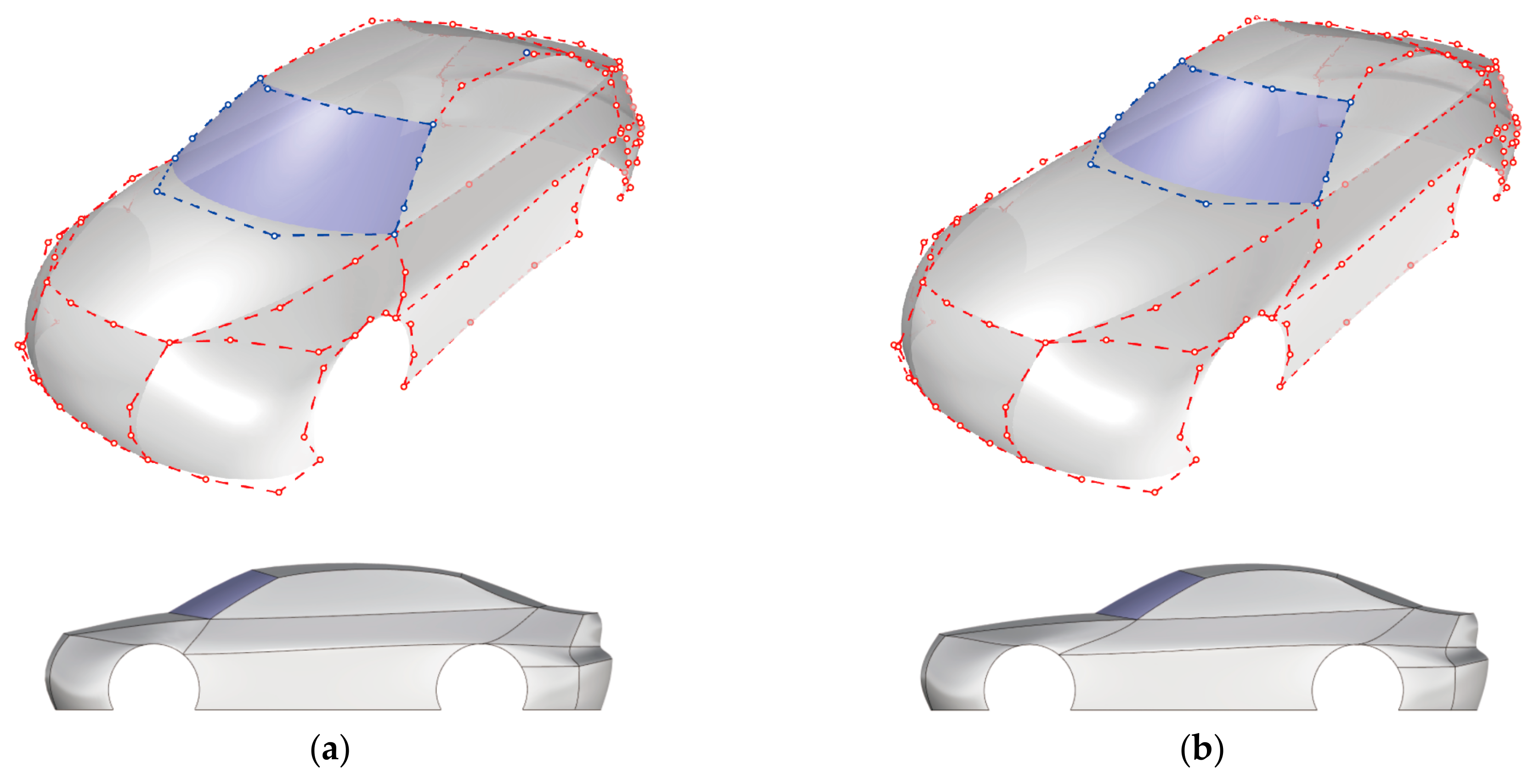
In the following optimization process, all the control points (the integral car modeling) of the hood surface in M0 are kept unchanged while the shape parameters (surface details) of the hood surface are optimized as variables for its CFD result. The coordinates of 12 control points on the four boundaries and the u and v directions of the hood surface are illustrated in Table 2 and Figure 12, respectively.
In the outflow field simulation of an automobile in CFD, the model is required to be closed. As the model template is composed of only 25 unclosed surfaces, five planes, including four nearly circular planes at the wheels and a large plane at the chassis, need to be generated to enclose the whole body.
The next step of CFD pretreatment is the generation of a computational grid, which is carried out in Gambit 2.4.6. The shape of the computational domain resembled a rectangular wind-tunnel test section. Its cross section covered 5 times the length upstream and 10 times the length downstream of the CAD vehicle model, 4 times the width on both left and right sides, and the height was 5 times the height of the model. The corresponding blockage ratio was about 1.12% according to our measurements, which is within the scope of 5% in typically accepted automobile aerodynamic testing (see [29]). The triangle mesh was set as 10 mm, and the hybrid tetrahedron was 10–200 mm. In addition, five layers of prism mesh were generated from the surface of the automobile model, and the thickness of the first layer was set as 8 mm. The two steps of the CFD pretreatment processes of the whole vehicle are shown in Figure 13.
To obtain the total pressure D in the upwind direction of the models, Ansys Fluent 16.2 and the k–ε turbulence model are used for aerodynamic computations. The drag coefficient Cd could be calculated according to:
C d = D 1 2 ρ v 2 A
where ρ is air density, v is vehicle speed (100 km/h), and A is the vehicle projection area in the windward direction. Since the adjustment of shape parameters only modifies the surface details, A, ρ and v remain unchanged, and the value of Cd is only related to D.
In this paper, the application of shape parameters in the optimization of the vehicle drag coefficient Cd will be explained in the order of one, two and three variables, respectively. In order to simplify the calculation, the variation range of shape parameters would be accurate to 0.5. As a contrast, the Cd of the original M0 model (the αu, γu, αv, and γv of the hood surface are all valued as 1) is 28.40% from the CFD simulation.
When only αu is used as a variable, according to CFD simulation, calculation and statistics, under the condition of keeping γu, αv and γv unchanged and valued as 1, the value curve of Cd caused by αu ∈ 1 ± 5 is shown in Figure 14. According to the algorithm for determining the range of shape parameters in Section 3.3, the curvature meets the requirement only when αu ∈ [−1.5, 2], which is marked as the red area. It could be concluded that Cd takes the optimal value 28.14% when αu is −1.5.
When αu and γu are taken as variables, the value surface of Cd with αu, γu ∈ 1 ± 5 is displayed in Figure 15. The ranges of αu and γu that meet the curvature requirements are [−1.5, 2] and [−1.5, 2.5], respectively. There are 64 parameter sets suitable for CFD simulation in these ranges, since some parameter sets at the limit (e.g., αu = −1.5 and γu = −1.5) do not meet the requirements. It could be concluded that Cd takes the optimal value 27.85% when αu = −1 and γu = −1.5.
As the hood surface is left–right symmetrical, the values of αv and γv are the same as they control the deformation of the surface in the left and right directions, respectively. Therefore, only three shape parameters at most could be optimized as variables on the hood surface. The range of αv (γv) that meets the curvature requirements is [−0.5, 5]. Since some parameter sets at the limit (e.g., αu = −1.5, γu = −1.5 and αv = γv = −0.5) do not meet the requirements, finally, there are 754 parameter sets suitable for CFD simulation in these ranges. The value of Cd in this range is illustrated in Figure 16. It could be concluded that Cd takes the optimal value 27.72% at αu = −1.5, γu = −0.5, αv = γv = 0.
For those surfaces which are not on the symmetrical plane, all four shape parameters should be used as variables to optimize the Cd. Its optimization method is similar to that mentioned above.
Figure 17 depicts the mean curvatures of the original hood surface and optimized surface. For this particular surface, with the four unchanged boundary curves and the four decreasing shape parameters, the mean curvature of the surface tends to be the same as that of the whole surface, but there is also a significant sudden change at the front end. CFD simulation confirms that such a change is beneficial to its aerodynamic performance.
For the other models M1–M50, the topological relationship between surfaces is the same as M0. Therefore, this method can also be applied to it, even though they have different boundary curve shapes. The influence (on both curvature and Cd) of shape parameters on different surfaces is not the same, and it should be analyzed and optimized separately according to their modelling characteristics, which cannot be simply generalized.
In conclusion, for model M0, the optimization on Cd could be carried out using one, two or three shape parameters as the variables, and the absolute value could be reduced by 0.68% when three variables were finally adopted. All the optimizations are carried out under the condition that the curvature of the surface meets the requirements, which means that surface modeling always keeps its initial trend without excessive modification. Therefore, it could be concluded that the shape parameters could affect the aerodynamic characteristics of the vehicle by controlling the surface modelling, and the optimization method could also ensure that both the shape and the Cd meet the needs of designers.

5. Conclusions

In order to simplify the over-complicated alternation of surface shape and to increase the efficiency in modeling design, this paper presents the SQ-Coons surface and studies the effects of parameters on its shape. Integrating the features of the Coons surface and novel Bézier-like surfaces, this new type of surface has the geometric advantage of interpolation on boundary curves and shape-adjustability, which makes it suitable in car styling design based on feature lines. Moreover, applying the SQ-Coons surface in car body design, a simplified vehicle model template and two modeling adjustment steps are established. Based on the aforementioned model template and steps, various car models could be built according to the template with corresponding parameters. Furthermore, an algorithm to ascertain the range of shape parameters has been proposed, by which the shape changes would not be excessive. This paper provides an optimization method of automobile aerodynamic performance based on a car model template. CFD simulation and statistical data show that shape parameters in some surfaces could be used as variables to optimize the automobile Cd. Notice that the optimization process is carried out within the limits of shape parameters, namely, the surface modelling would not change excessively. This is because, for automotive design, the purpose of optimization is to find the optimal combination of its shape and aerodynamic characteristics.
However, as the surfaces are only G0 continuous at present, the model template is not very detailed. Consequently, only the requirements of the early stage of body design can be met, which may affect the aesthetics or CFD. Therefore, an algorithm for segmenting on the SQ-Coons surface will be proposed in our future research, to establish a vehicle model with higher complexity and a richer level of detail. In addition, we will try to introduce the perceptual evaluation method for aesthetic evaluation, in order to develop the current method to achieve optimal automotive styling.

Author Contributions

Conceptualization, F.L., X.J. and G.H.; Methodology, F.L. and X.J.; Software, F.L. and J.G.; Validation, J.G.; Formal Analysis, F.L.; Investigation, F.L. and J.G.; Resources, X.J.; Data Curation, F.L.; Writing—Original Draft Preparation, F.L. and X.J.; Writing—Review and Editing, F.L., X.J., G.H. and J.G.; Visualization, F.L., X.J. and G.H.; Supervision, X.J. and G.H.; Funding Acquisition, G.H.

Funding

This research was funded by the National Natural Science Foundation of China Grant No. 51875454 and Shaanxi Province Education Department Humanities and Social Sciences Research Plan of China No. 18JK0538.

Acknowledgments

We thank the anonymous reviewers for their insightful suggestions and recommendations, which led to the improvements of the presentation and content of the paper.

Conflicts of Interest

The authors declare that they have no conflict of interest.

References

  1. Bodein, Y.; Rose, B.; Caillaud, E. A roadmap for parametric CAD efficiency in the automotive industry. Comput. Aided Des. 2013, 45, 1198–1214. [Google Scholar] [CrossRef]
  2. Hsiao, S.W.; Tsai, H.C. Applying a hybrid approach based on fuzzy neural network and genetic algorithm to product form design. Int. J. Ind. Ergon. 2005, 35, 411–428. [Google Scholar] [CrossRef]
  3. Gunpinar, E.; Gunpinar, S. A shape sampling technique via particle tracing for CAD models. Graph. Models 2018, 96, 11–29. [Google Scholar] [CrossRef]
  4. Bluntzer, J.B.; Ostrosi, E.; Sagot, J.C. Car styling: A CAD approach to identify, extract and interpret characteristic lines. Procedia CIRP 2014, 21, 258–263. [Google Scholar] [CrossRef]
  5. Ostrosi, E.; Bluntzer, J.B.; Zhang, Z.F.; Stjepandić, J. Car style-holon recognition in computer-aided design. J. Comput. Des. Eng. 2018, in press. [Google Scholar] [CrossRef]
  6. Guo, J.W.; Ding, F.; Jia, X.H.; Yan, D.M. Automatic and high-quality surface mesh generation for CAD models. Comput. Aided Des. 2019, 109, 49–59. [Google Scholar] [CrossRef]
  7. Xiong, Y.; Li, Y.; Pan, P.Y.; Chen, Y. A regression-based Kansei engineering system based on form feature lines for product form design. Adv. Mech. Eng. 2016, 8. [Google Scholar] [CrossRef] [Green Version]
  8. Cheutet, V.; Catalano, C.E.; Pernot, J.P.; Falcidieno, B.; Giannini, F.; Leon, J.C. 3D sketching for aesthetic design using fully free-form deformation features. Comput. Graph. 2005, 29, 916–930. [Google Scholar] [CrossRef] [Green Version]
  9. Tian, G.D.; Zhang, H.H.; Jia, H.F.; Liu, Y.M.; Xu, G.; Wang, J. Automotive style design assessment and sensitivity analysis using integrated analytic hierarchy process and technique for order preference by similarity to ideal solution. Adv. Mech. Eng. 2016, 8. [Google Scholar] [CrossRef] [Green Version]
  10. Kumar, B.; Sarkar, P. Prediction of future car forms based on historical trends. Perspect. Sci. 2016, 8, 764–766. [Google Scholar] [CrossRef] [Green Version]
  11. Cluzel, F.; Yannou, B.; Dihlmann, M. Using evolutionary design to interactively sketch car silhouettes and stimulate designer’s creativity. Eng. Appl. Artif. Intell. 2012, 25, 1413–1424. [Google Scholar] [CrossRef]
  12. Hyun, K.H.; Lee, J.H.; Kim, M.; Cho, S. Style synthesis and analysis of car designs for style quantification based on product appearance similarities. Adv. Eng. Inform. 2015, 29, 483–494. [Google Scholar] [CrossRef]
  13. Hu, G.; Wu, J.L.; Qin, X.Q. A novel extension of the Bézier model and its applications to surface modeling. Adv. Eng. Softw. 2018, 125, 27–54. [Google Scholar] [CrossRef]
  14. Shen, W.Q.; Wang, G.Z. Geometric shapes of C-Bézier curves. Comput. Aided Des. 2015, 58, 242–247. [Google Scholar] [CrossRef]
  15. Han, X.A.; Ma, Y.C.; Huang, X.L. The cubic trigonometric Bézier curve with two shape parameters. Appl. Math. Lett. 2009, 22, 226–231. [Google Scholar] [CrossRef]
  16. Hu, G.; Bo, C.C.; Wu, J.L.; Wei, G.; Hou, F. Modeling of free-form complex curves using SG-Bézier curves with constraints of geometric continuities. Symmetry 2018, 10, 545. [Google Scholar] [CrossRef]
  17. Chu, L.C.; Zeng, X.M. Constructing curves and triangular patches by Beta functions. J. Comput. Appl. Math. 2014, 260, 191–200. [Google Scholar] [CrossRef]
  18. Qin, X.Q.; Hu, G.; Zhang, N.J.; Shen, X.L.; Yang, Y. A novel extension to the polynomial basis functions describing Bezier curves and surfaces of degree n with multiple shape parameters. Appl. Math. Comput. 2013, 223, 1–16. [Google Scholar] [CrossRef]
  19. Zhang, N.J. Study of Curves & Surfaces Theory and Relevant Algorithm with Shape Parameters in Geometric Design. Master’s Thesis, Xi’An University of Technology, Xi’an, China, 2011. [Google Scholar]
  20. Xie, C.; Li, J.C.; Zhong, Y.E.; Yang, L.; Liu, C.Y. Trigonometric Coons Patch with Shape Parameters. Adv. Mater. Res. 2012, 482–484, 595–598. [Google Scholar] [CrossRef]
  21. Wang, J.X.; Dong, Y.; Ni, J. Biquadrate trigonometric polynomial Coons patch with adjustable parameters. J. Dalian Jiaotong Univ. 2013, 34, 110–112. [Google Scholar]
  22. Pei, F.; Han, X.L.; Li, Y. Structure and splice of Coons patched with shape parameters. Comput. Eng. Appl. 2013, 49, 163–166. [Google Scholar]
  23. Zou, Q. Coons surfaces based on rational blending function with shape parameters and its properties. J. Huaibei Norm. Univ. (Nat. Sci. Ed.) 2013, 34, 6–9. [Google Scholar]
  24. Piegl, L.; Tiller, W. The NURBS Book, 2nd ed.; Springer-Verlag: New York, NY, USA, 1997; pp. 496–507. [Google Scholar]
  25. Hsu, M.C.; Wang, C.L.; Xu, F.; Herrema, A.J.; Krishnamurthy, A. Direct immersogeometric fluid flow analysis using B-rep CAD models. Comput. Aided Geom. Des. 2016, 43, 143–158. [Google Scholar] [CrossRef] [Green Version]
  26. Chowdhury, H.; Islam, R.; Hussein, M.; Zaid, M.; Loganathan, B.; Alam, F. Design of an energy efficient car by biomimicry of a boxfish. Energy Procedia 2019, 160, 40–44. [Google Scholar] [CrossRef]
  27. Cheng, S.Y.; Tsubokura, M.; Nakashima, T.; Nouzawa, T.; Okada, Y. A numerical analysis of transient flow past road vehicles subjected to pitching oscillation. J. Wind Eng. Ind. Aerodyn. 2011, 99, 511–522. [Google Scholar] [CrossRef] [Green Version]
  28. Cheng, S.Y.; Tsubokura, M.; Nakashima, T.; Okada, Y.; Nouzawa, T. Numerical quantification of aerodynamic damping on pitching of vehicle-inspired bluff body. J. Fluids Struct. 2012, 30, 188–204. [Google Scholar] [CrossRef] [Green Version]
  29. Cheng, S.Y.; Tsubokura, M.; Okada, Y.; Nouzawa, T.; Nakashima, T.; Doh, D.H. Aerodynamic stability of road vehicles in dynamic pitching motion. J. Wind Eng. Ind. Aerodyn. 2013, 122, 146–156. [Google Scholar] [CrossRef] [Green Version]
  30. Hassan, S.M.R.; Islam, T.; Ali, M.; Islam, M.Q. Numerical study on aerodynamic drag reduction of racing cars. Procedia Eng. 2014, 90, 308–313. [Google Scholar] [CrossRef]
  31. Fu, C.; Uddin, M.; Robinson, A.C. Turbulence modeling effects on the CFD predictions of flow over a NASCAR Gen 6 racecar. J. Wind Eng. Ind. Aerodyn. 2018, 176, 98–111. [Google Scholar] [CrossRef]
  32. Aljure, D.E.; Calafell, J.; Baez, A.; Oliva, A. Flow over a realistic car model: Wall modeled large eddy simulations assessment and unsteady effects. J. Wind Eng. Ind. Aerodyn. 2018, 174, 225–240. [Google Scholar] [CrossRef] [Green Version]
  33. Aljure, D.E.; Lehmkuhl, O.; Rodríguez, I.; Oliva, A. Flow and turbulent structures around simplified car models. Comput. Fluids 2014, 96, 122–135. [Google Scholar] [CrossRef] [Green Version]
  34. Aljure, D.E.; Lehmkuhl, O.; Martinez, D.; Favre, F.; Oliva, A. On the IBM approximation for the wheel aerodynamic simulation. In Proceedings of the First International Conference in Numerical and Experimental Aerodynamics of Road Vehicles and Trains (Aerovehicles 1), Bordeaux, France, 23–25 June 2014. [Google Scholar]
  35. Islam, A.; Gaylard, A.; Thornber, B. A detailed statistical study of unsteady wake dynamics from automotive bluff bodies. J. Wind Eng. Ind. Aerodyn. 2017, 171, 161–177. [Google Scholar] [CrossRef]
  36. Ashton, N.; Revell, A. Key factors in the use of DDES for the flow around a simplified car. Int. J. Heat Fluid Flow 2015, 54, 236–249. [Google Scholar] [CrossRef]
Figure 1. The approaches to obtain four virtual control points besides the boundary control points by transforming the Coons surface into the Bézier surface: (a) Four boundary curves and 12 control points on the Bézier surface; (b) The Coons surface generated accroading to the boundary curves; (c) 16 control points of the Bézier surface converted from the Coons surface.
Applsci 09 02339 g001
Figure 2. In order to generate the shape-adjustable surface proposed in this paper, three special surfaces are constructed: (a) The surface R1 of Bézier basis functions in its u-direction and CE-Bézier basis functions in its v-direction; (b) The surface R2 of CE-Bézier basis functions in its u-direction and Bézier basis functions in its v-direction; (c) The Coons surface S constructed by four CE-Bézier curves.
Applsci 09 02339 g002
Figure 3. The modelling of the surface central part could be affected by the shape parameters, so as to be close to or far from the virtual control points.
Applsci 09 02339 g003
Figure 4. Effect on mean curvature of various shape parameters αu and γu ∈ [−3, 5] on a SQ-Coons surface modelling.
Applsci 09 02339 g004
Figure 5. The model template of an automobile proposed in this article: (a) Modeling features are extracted from real models; (b) 156 control points of boundary curves; (c) The template consists of 25 quadrilateral surfaces.
Applsci 09 02339 g005aApplsci 09 02339 g005b
Figure 6. Effect of altering the control point on vehicle modeling: (a) Moving the control points of the windshield forward; (b) Moving the control points back.
Applsci 09 02339 g006
Figure 7. Effect of altering the shape parameters on hood surface: (a) αu, γu, αv, γv = 1; (b) αu, γu, αv, γv = –3.
Applsci 09 02339 g007
Figure 8. Some key isocurves of a surface are used to define the surface curvature: (a) The isocurves u = 0, 0.5, 1 in direction-u; (b) The isocurves v = 0, 0.5, 1 in direction-v.
Applsci 09 02339 g008
Figure 9. Part M1–M15 in the car sample library built from the model template.
Applsci 09 02339 g009
Figure 10. The difference degrees d of the whole body are divided into three types according to the different surfaces and directions: (a) In the nine central surfaces, the type-1 difference degrees d in the driving direction; (b) The type-2 difference degrees d in the left–right direction; (c) The type-3 difference degrees d on the other surfaces.
Applsci 09 02339 g010
Figure 11. Numerical distribution statistics of three difference degrees d in 50 vehicle models: (a) Type-1 difference degree; (b) Type-2 difference degree; (c) Type-3 difference degree.
Applsci 09 02339 g011
Figure 12. The key isocurves of hood surfaces in the model M0.
Applsci 09 02339 g012
Figure 13. The pretreatment of computational fluid dynamics (CFD) on the the model M0.
Applsci 09 02339 g013
Figure 14. The effect of αu ∈ 1 ± 5 on Cd when γu = αv = γv = 1.
Applsci 09 02339 g014
Figure 15. The effect of αu, γu ∈ 1 ± 5 on Cd when αv = γv = 1.
Applsci 09 02339 g015
Figure 16. The effect of αu, γu ∈ 1 ± 5 and αv (γu) ∈ [–0.5, 5] on Cd.
Applsci 09 02339 g016
Figure 17. The change in mean curvature on the hood surface before and after optimization.
Applsci 09 02339 g017
Table 1. Comparison of geometric characteristics of various types of parametric surfaces.
Surface TypeControl PointsShape Adjustable?Interpolates Boundaries?Needs Cross-Boundary Derivatives?
SQ-Coons12YesYesNo
Bézier *16NoYesN/A
NURBS *16YesYesN/A
CE-Bézier16YesNoN/A
Bilinearly Coons *12NoYesNo
Bicubically Coons *12NoYesYes
Extended Coons *12YesYesYes
* Bicubic surface.
Table 2. The coordinates of 12 control points of the SQ-Coons hood surface *.
piji
0123
j06.73, −41.30, 50.3443.44, −59.96, 72.9991.17, −69.67, 74.53136.73, −72.79, 78.75
1−2.32, −15.18, 50.98 117.38, −27.68, 82.37
2−2.32, 15.18, 50.98117.38, 27.68, 82.37
36.73, 41.30, 50.3443.44, 59.96, 72.9991.17, 69.67, 74.53136.73, 72.79, 78.75
* The contact point between the vehicle fore-end and ground is taken as the coordinate origin; the driving direction is taken as the negative direction of the X-axis; the right-direction of the driver is taken as the positive direction of the Y-axis; the upward direction is taken as the positive direction of the Z-axis; the measuring unit is cm.

