MgO Modified with MgF2 as an Electrolyte Immobilizing Agent for the High-Temperature Cells

 , ,
, ,
Abstract
:1. Introduction
2. Materials and Methods
2.1. Preparation of Materials
2.1.1. Preparation of MgO and MgF2-MgO System
2.1.2. Eutectic LiCl-KCl-RbCl Mixture
2.1.3. Preparation of Electrolyte Pellets
2.2. Material Characterization
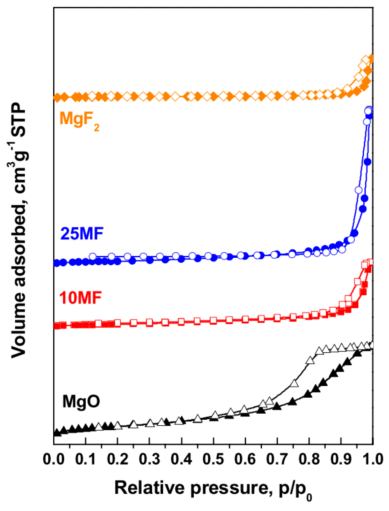
2.2.1. Determination of Surface Area, Pore Volume, and Pore Diameter
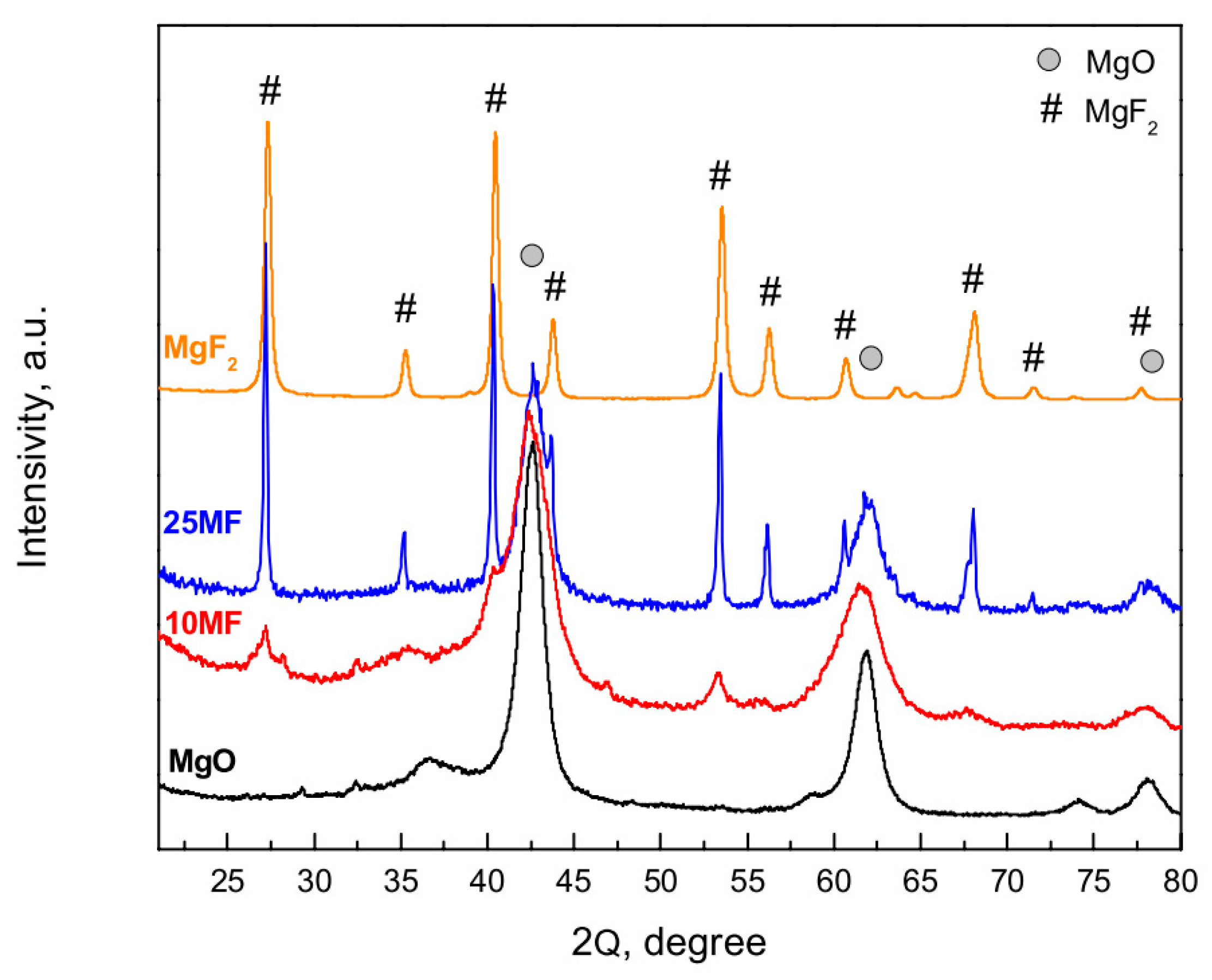
2.2.2. X-Ray Diffraction Analysis
2.2.3. Determination of MgF2 by the Pyrohydrolysis Method
2.2.4. Measurement of the Specific Volume of the Pellet
2.2.5. Dimensional Stability and Electrolyte Leakage Test
2.2.6. Measurement of the Mechanical Strength of the Pellet
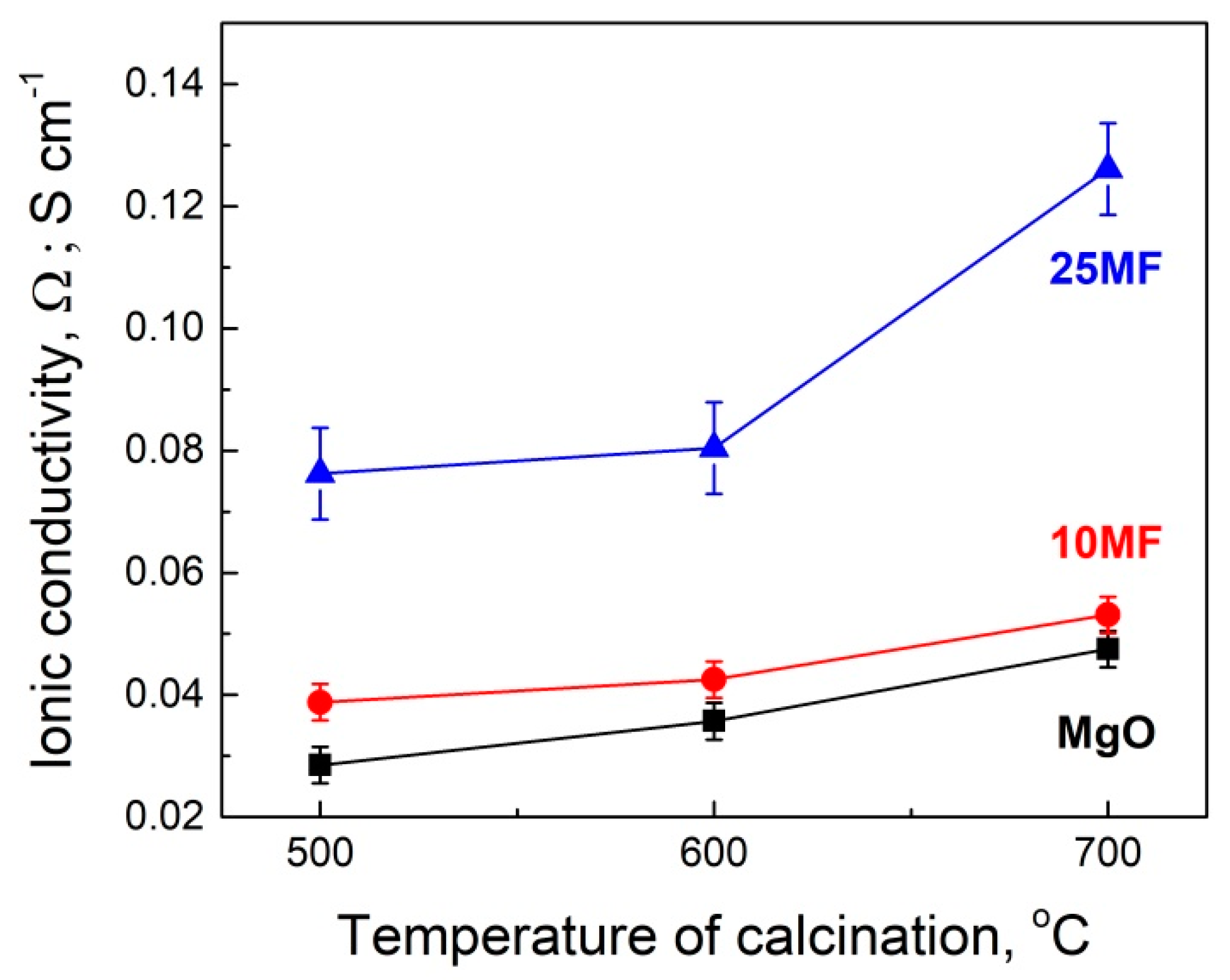
2.2.7. Determination of Ionic Conductivity
3. Results and Discussion
4. Conclusions
- The impregnation of magnesia with magnesium fluoride results in the covering of the MgO surface with MgF2.
- The surface MgF2 protects MgO against CO2, which limits the increase of the internal pressure in the activated cell.
- The application of the MgF2/MgO system as a filler in the high-temperature cells considerably improves parameters, such as the mechanical strength and ionic conductivity, of the molten electrolyte in the electrolyte–filler pellets.
- The MgF2/MgO system is a promising filler for high-temperature cells.
Author Contributions
Funding
Conflicts of Interest
References
- Styczyński, S.; Czajka, B.; Solopa, W.; Rydzyńska, B.; Ciszewski, B.A. The effect of the heating medium on the electric parameters of a thermal battery with the electrochemical system Li/LiCl-KCl-RbCl-LiF/FeS2. Pol. J. Chem. Technol. 2006, 8, 80–82. [Google Scholar]
- Linden, D.; Reddy, T. Handbook of Batteries; Mc Grow Hill: New York, NY, USA, 2002. [Google Scholar]
- White, S.M. Molten Salts Techniques vol. 1(2); Lovering, D.G., Cale, R.J., Eds.; Springer: New York, NY, USA, 1983. [Google Scholar]
- Masset, P.; Guidotti, R.A. Thermal activated (thermal) battery technology: Part II. Molten salt electrolytes. J. Power Sources 2007, 164, 397–414. [Google Scholar] [CrossRef]
- Czajka, B.; Zieliński, M.; Wojciechowska, M.; Tomska-Foralewska, I. Modification of MgO as an immobilizing agent for molten electrolyte. J. Solid State Electr. 2014, 18, 2351–2358. [Google Scholar] [CrossRef]
- Zieliński, M.; Czajka, B.; Pietrowski, M.; Kiderys, A.; Tomska-Foralewska, I.; Przystajko, W.; Wojciechowska, M. The effect of MgO-MgF2 synthesis method on the electrolyte binding ability in thermal batteries. Chem. Sel. 2018, 3, 294–296. [Google Scholar] [CrossRef]
- Zieliński, M.; Czajka, B.; Pietrowski, M.; Tomska-Foralewska, I.; Alwin, E.; Kot, M.; Wojciechowska, M. MgO-MgF2 system obtained by sol-gel method as an immobilizing agent of electrolyte applied in the high temperature cells. J. Sol Gel Sci. Technol. 2017, 84, 368–374. [Google Scholar] [CrossRef]
- Zieliński, M. The catalytic and physico-chemical properties of Ni/MgF2-MgO catalysts. Appl. Catal. A 2012, 449, 15–22. [Google Scholar] [CrossRef]
- Wojciechowska, M.; Wajnert, A.; Tomska-Foralewska, I.; Zieliński, M.; Czajka, B. Properties of magnesium oxo-fluoride supports for metal catalysts. Catal. Lett. 2009, 128, 77–82. [Google Scholar] [CrossRef]
- Dressler, V.L.; Pozebon, D.; Flores, É.L.M.; Paniz, J.N.G.; Flores, É.M.M. Determination of Fluoride in Coal Using Pyrohydrolysis for Analyte Separation. J. Braz. Chem. Soc. 2003, 14, 334–338. [Google Scholar] [CrossRef]
- Czajka, B.; Wachowski, L. Some thermochemical properties of high calorific mixture of Fe-KClO4. Cent. Eur. J. Energ. Mater. 2005, 2, 55–68. [Google Scholar]
- Thommes, M.; Kaneko, K.; Neimark, A.V.; Olivier, J.P.; Rodriguez-Reinoso, F.; Rouquérol, J.; Sing, K.S.W. Physisorption of gases, with special reference to the evaluation of surface area and pore size distribution (IUPAC Technical Report). Pure Appl. Chem. 2015, 87, 1051–1069. [Google Scholar] [CrossRef] [Green Version]

| Sample Code | MgF2 Content *, (Pyrohydrolysis) mol.% | MgF2 Content, (XRD) mol.% | Calcination Temperature, °C | BET Surface Area #, m2 g−1 | Total Pore Volume #, cm3 g−1 | Average Pore Diameter #, nm |
|---|---|---|---|---|---|---|
| MgO | 0 | 0 | 500 | 161 | 0.29 | 9.1 |
| 600 | 164 | 0.45 | 22.6 | |||
| 700 | 130 | 0.49 | 42.3 | |||
| 10 MF | 11.7 ± 0.6 | 10.5 | 500 | 43.4 | 0.17 | 18.6 |
| 600 | 52.3 | 0.28 | 22.0 | |||
| 700 | 51.3 | 0.35 | 26.8 | |||
| 25 MF | 22.9 ± 1.1 | 21.8 | 500 | 38.9 | 0.26 | 26.3 |
| 600 | 44.7 | 0.31 | 27.9 | |||
| 700 | 36.9 | 0.31 | 29.4 | |||
| MgF2 | 100 | 100 | 500 | 30.7 | 0.21 | 21.5 |
| 600 | 15.2 | 0.25 | 36.2 | |||
| 700 | 8.6 | 0.58 | 56.2 |
| Calcination Temperature of the Electrolyte Immobilizing Agent, °C | MgO | 10 MF | 25 MF | ||||||
|---|---|---|---|---|---|---|---|---|---|
| S, % | MS, N | V, % | S, % | MS, N | V, % | S, % | MS, N | V, % | |
| 500 | 7.6 ± 0.3 | 4.12 ± 0.08 | 47.8 ± 0.4 | 12.7 ± 0.4 | 6.49 ± 0.08 | 49.1 ± 0.4 | 7.0 ± 0.4 | 6.02 ± 0.08 | 48.8 ± 0.4 |
| 600 | 7.0 ± 0.2 | 3.74 ± 0.08 | 43.1 ± 0.4 | 14.9 ± 0.4 | 5.83 ± 0.08 | 47.6 ± 0.4 | 12.7 ± 0.5 | 5.89 ± 0.08 | 47.8 ± 0.4 |
| 700 | 6.2 ± 0.2 | 3.82 ± 0.08 | 30.0 ± 0.4 | 20.4 ± 0.5 | 5.43 ± 0.08 | 47.5 ± 0.4 | 70.3 ± 1.1 | 5.92 ± 0.08 | 41.6 ± 0.4 |
| Calcination Temperature of the Immobilizing Agent, °C | MgO | 10 MF | 25 MF |
|---|---|---|---|
| 500 | 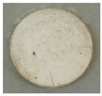 | 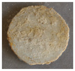 | 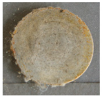 |
| 600 | 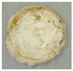 | 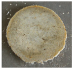 |  |
| 700 |  | 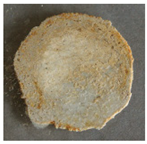 | 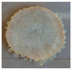 |
© 2019 by the authors. Licensee MDPI, Basel, Switzerland. This article is an open access article distributed under the terms and conditions of the Creative Commons Attribution (CC BY) license (http://creativecommons.org/licenses/by/4.0/).
Share and Cite
Zieliński, M.; Kiderys, A.; Pietrowski, M.; Czajka, B.; Tomska-Foralewska, I.; Wojciechowska, M. MgO Modified with MgF2 as an Electrolyte Immobilizing Agent for the High-Temperature Cells. Appl. Sci. 2019, 9, 2642. https://doi.org/10.3390/app9132642
Zieliński M, Kiderys A, Pietrowski M, Czajka B, Tomska-Foralewska I, Wojciechowska M. MgO Modified with MgF2 as an Electrolyte Immobilizing Agent for the High-Temperature Cells. Applied Sciences. 2019; 9(13):2642. https://doi.org/10.3390/app9132642
Chicago/Turabian StyleZieliński, Michał, Angelika Kiderys, Mariusz Pietrowski, Bogdan Czajka, Iwona Tomska-Foralewska, and Maria Wojciechowska. 2019. "MgO Modified with MgF2 as an Electrolyte Immobilizing Agent for the High-Temperature Cells" Applied Sciences 9, no. 13: 2642. https://doi.org/10.3390/app9132642