Article

Joining of AZ31 Magnesium Alloy to 6061 Aluminum Alloy with Sn-Zn Filler Metals Containing Trace Rare Earth Elements

Department of Mechanical Engineering, National Yunlin University of Science & Technology, Touliu 64002, Yunlin, Taiwan
*
Author to whom correspondence should be addressed.
Appl. Sci. 2019, 9(13), 2655; https://doi.org/10.3390/app9132655
Submission received: 13 May 2019 / Revised: 1 June 2019 / Accepted: 13 June 2019 / Published: 29 June 2019
(This article belongs to the Section Mechanical Engineering)

Abstract

:
In this study, AZ31 magnesium alloy and 6061 aluminum alloy were joined with Sn-xZn (x = 5, 10, 20 and 30 wt.%) fillers containing trace rare earth elements at 250 °C in air without the use of flux or a wetting layer. The bond shear strengths of AZ31 magnesium alloy/6061 aluminum alloy joints with Sn-5Zn-0.1RE, Sn-10Zn-0.1RE, Sn-20Zn-0.1RE, and Sn-30Zn-0.1RE fillers were determined to be 14.84, 17.08, 19.39 and 20.86 MPa, respectively. The shear strengths increased with increasing Zn content. The joint strengths of all four alloys significantly decreased with increasing aging time at 150 °C.

1. Introduction

Magnesium and aluminum alloys have the merits of low density and high specific strength. Thus, both alloys have been widely used in automobiles, aircraft, bicycles, computers and communication equipment. Magnesium alloys are the lightest structural alloys with high damping capacity and easy recyclability. However, their poor corrosion resistance seriously impedes wider application. Aluminum alloys have good surface decoration characteristics and excellent corrosion resistance. It would therefore be of practical significance to join magnesium alloy with aluminum alloy, as doing so could promote the application of these alloys and thereby further improve existing light-weight solutions [1,2,3].
Due to discrepancies in their thermal expansion coefficients, joining magnesium alloy and aluminum alloys by conventional welding methods is a challenge. Moreover, due to the low melting temperatures of both alloys and the high affinities of magnesium and aluminum to oxygen, fusion welding of both alloys is considered difficult. Spot-welding, friction-stir welding, tungsten-inert-gas welding and laser-welding processes result in the formation of brittle MgAl, Al3Mg2 and Al12Mg17 intermetallic compounds (IMCs) in the joint area [4,5,6]. Stress-induced cracks alongside the unexpected brittle intermetallic compounds results in considerably reduced bonding strength. Classical welding methods therefore prove unsuitable for bonding magnesium alloy and aluminum alloys. An effective method of joining such dissimilar materials is brazing. Commercial braze is used to join aluminum alloys such as Al-Si alloys.
In order to carry out a high-quality welding of AA7020 aluminum alloy, the laser welding process with Al-5Ti-B and Al-5Mg filler metal was developed by Adisa et al. [7]. Unfortunately, these aluminum brazes have high melting temperatures in the range of 575–610 °C. Although zinc, copper, tin, magnesium and germanium have been identified as additive elements in Al-Si alloys to reduce the brazing temperature to around 500 °C, this temperature is also too high relative to the solidus temperatures of high-strength aluminum alloys [8,9]. Magnesium alloys and aluminum alloys soften greatly at temperatures above 300 °C. Moreover, high-temperature joining processes lead to the problem of oxidation. Gorjan et al. [10,11] studied the bonding of A356 aluminum alloy/Al2O3 using ultrasonic-assisted soldering with Sn-Ag-Ti solder containing trace rare earth element (Ce) and wetting promoter (Ga). Results of their studies demonstrated that the addition of rare earth element in solder can effectively enhance the solderability and a satisfactory joint of aluminum can thereby be obtained at 250 °C in air. Low-temperature soldering with Sn-Zn solders is suitable for joining temperature-sensitive aluminum and magnesium alloys. Wang et al. [12] found that the average shear strength of magnesium/aluminum alloy joints bonded with Sn-Zn alloy increased with increasing Zn content, and a high joining strength of 70.73 MPa was achieved with Sn-30Zn filler in argon protective atmosphere.
One of the key issues hindering their application is the poor oxidation resistance of Sn-Zn filler metals [13,14]. Some studies have indicated that adding trace amounts of rare-earth elements in solders significantly promotes the wetting of filler metals [15,16,17]. Furthermore, solders with rare-earth elements can prevent the formation of oxides on their surfaces. Wu et al. [18] demonstrated that adding the rare earth (RE) elements Ce or La in concentrations of 0.05 wt.% and 0.1 wt.% into Sn-9Zn alloy reduced the wetting angle and thereby increased the wetting force. Zhang et al. [19] reported that the oxidation resistance of Sn-9Zn solder can also be effectively improved by adding trace amounts of rare earth elements (0.08% Er).
Filler metals containing rare earth elements have been successful in directly bonding notoriously unweldable materials such as ceramics, composites, silicon, graphite and micro-arc oxidized titanium and aluminum alloys [20,21,22,23,24,25,26,27,28,29,30,31] in air. Sn-xZn-0.1RE (x = 5, 10, 20 and 30 wt.%) fillers had the same solidus temperature of about 199 °C, corresponding to the eutectic temperature of Zn-Sn binary alloys. Endothermic peaks were found in DSC curves of Sn-5Zn-0.1RE, Sn-10Zn-0.1RE, Sn-20Zn-0.1RE, and Sn-30Zn-0.1RE alloys at 203.5, 202.4, 205.8 and 206.8 °C, respectively [32]. The Sn-10Zn-0.1RE alloy near the Sn-9Zn eutectic composition exhibited the lowest melting point. The melting point of the hypoeutectic Sn-5Zn-0.1RE alloy and of hypereutectic Sn-20Zn-0.1RE and Sn-30Zn-0.1RE alloys increased with increasing zinc content.
All of the microstructures of Sn-Zn-RE alloys consisted of β-Sn solid solution matrix phase and Zn rich phase. The microstructure of the hypoeutectic Sn-5Zn-0.1RE alloy mainly consisted of the β-Sn phase and Sn-Zn eutectics. The hypereutectic Sn-10Zn-0.1RE alloy had alternate distributions of Sn-Zn eutectic phase and needle-like Zn-rich phase. The microstructures of hypereutectic Sn-20Zn-0.1RE and Sn-30Zn-0.1RE alloys exhibited coarse clusters of Zn and needle-like Zn particles embedded in the β-Sn solid solution matrix phase. The microstructures of Sn-Zn solders were refined by adding rare earth elements.
In comparison to the study of Wang et al. [12], the size of the β-Sn solid solution matrix phase of hypoeutectic Sn-Zn alloy decreased from 70–100 μm to 15–45 μm with the addition of rare-earth elements. Furthermore, the number and size of coarse Zn-rich phase in hypereutectic Sn-Zn alloys decreased significantly with the addition of trace amounts of rare earth elements [32]. The present work investigates the interfacial reactions and solderability in air of AZ31 magnesium and 6061 aluminum alloy joints with Sn-Zn filler metals containing rare-earth elements. The influence of Zn content and thermal aging duration on the interfacial microstructures and mechanical properties of the joints were also studied in detail.

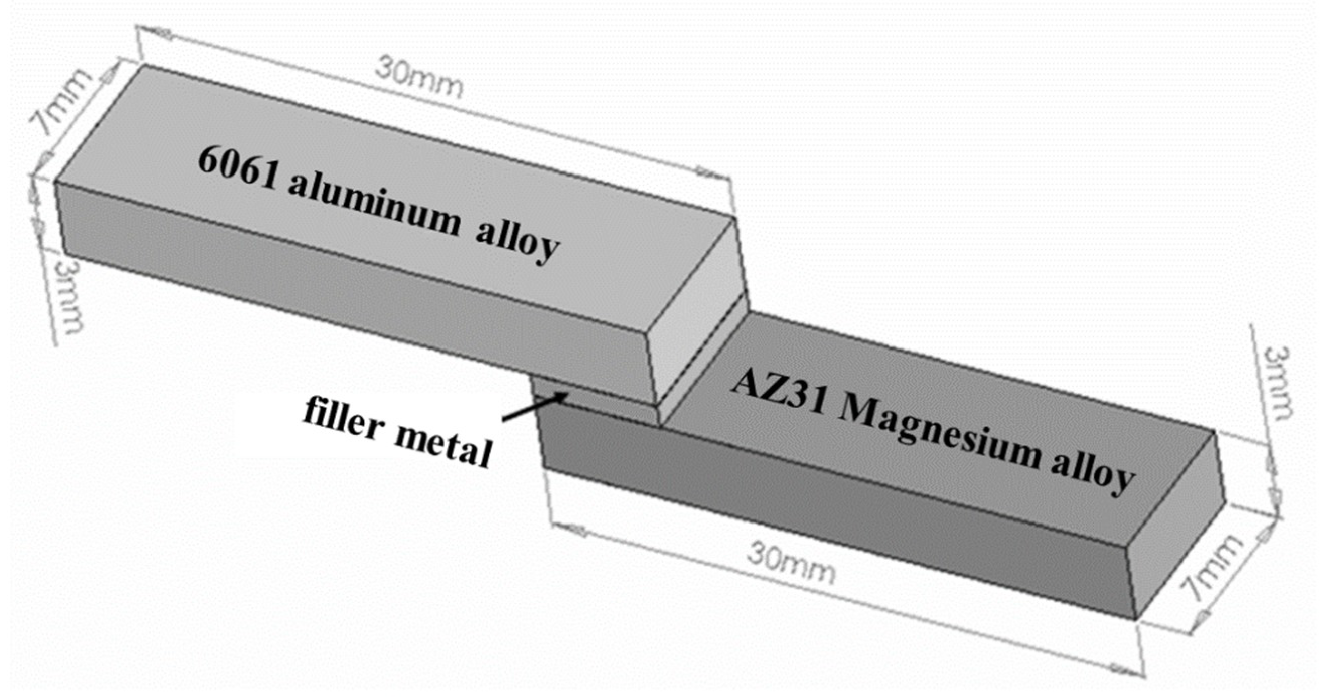
2. Experimental Section

The Sn-5Zn-0.1RE, Sn-10Zn-0.1RE, Sn-20Zn-0.1RE and Sn-30Zn-0.1RE filler metals used in this study were prepared by melting tin and zinc slugs of 99.99% purity and a rare earth element (RE) mixture of 99% purity in a vacuum arc furnace under a high-purity argon atmosphere. The mixed rare earth element with the advantage of low cost used in the study combined several characteristics of different rare-earth elements which had a composition by mass of 77.82% La, 16.84% Pr, 3.24% Ce, and 2.10% Nd. To ensure a homogenous composition within the filler metals, the alloys were stirred for 30 min. Each cast ingot was 20 mm in diameter, about 100 g in weight and was rolled into 200 μm thick foil. The base materials used in the joining experiments were AZ31 magnesium alloy and 6061 aluminum alloy. The compositions of the two base materials are listed in Table 1.
The materials to be joined were cut into strips of 30 mm × 7 mm × 3 mm. Prior to soldering, both the bonding and the filler metal surfaces were ground down to grade 1200 with SiC paper. The 200 μm thick filler metal foils were then placed on base material surfaces to be melted on a heating plate. The Sn-xZn-0.1RE (x = 5, 10, 20 and 30 wt.%) fillers had the same solidus temperature of about 199 °C. In order to prevent the oxidation and volatility of zinc, the temperature used for soldering was controlled at about 230 °C. After the molten solder was agitated for 30 s, the AZ31 magnesium and the 6061 aluminum alloy specimens were overlapped, with an overlap length of 5 mm. The joints were then removed from the heating platform and held firmly in place for 30 seconds to allow cooling to solidify the molten solder.
Each set of specimens was aged at 150 °C in air and then cross-sectioned. A standard metallographic procedure was applied to all joints. At least 3 shear tests were carried out for each condition and the average shear strength values were determined. The geometry and dimensions of the soldered specimens subjected to shear testing were shown in Figure 1. Shear tests were carried out using a tensile testing machine (Hung Ta Instrument Co., Ltd. HT-2402, Taizhong, Taiwan). Fractured surfaces and the microstructures of the bonding interfaces were characterized with a field-emission scanning electron microscope (FE-SEM, Philips XL40) coupled with energy dispersive X-ray (EDX) to investigate the bonding mechanism and related interfacial reactions.

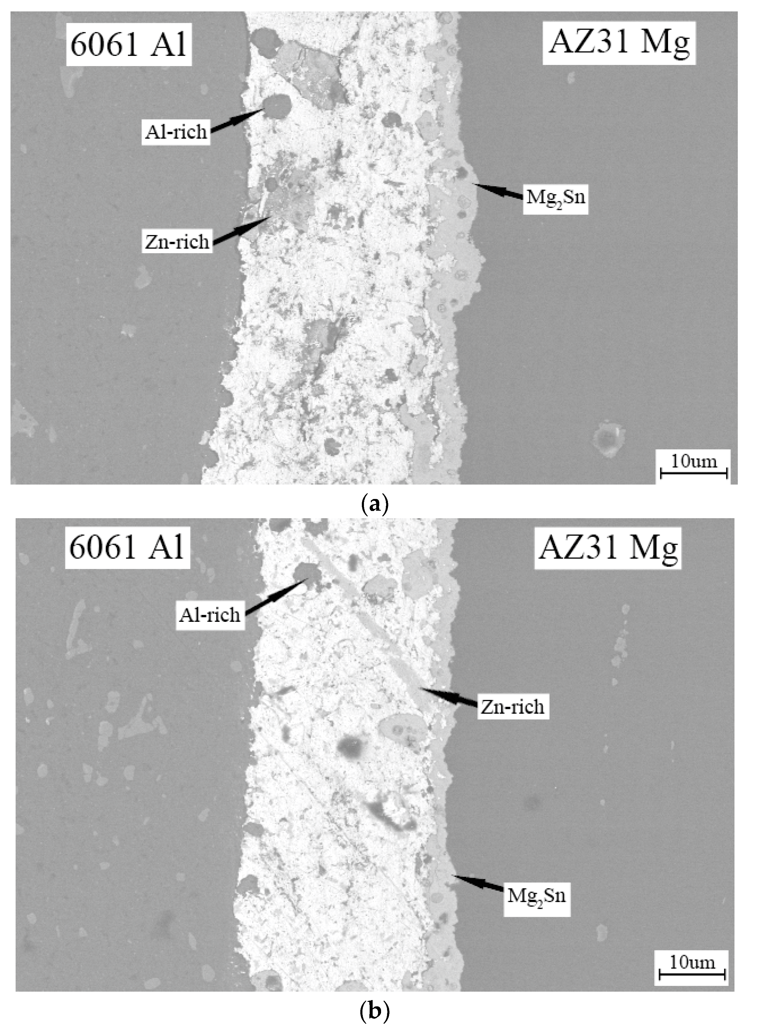
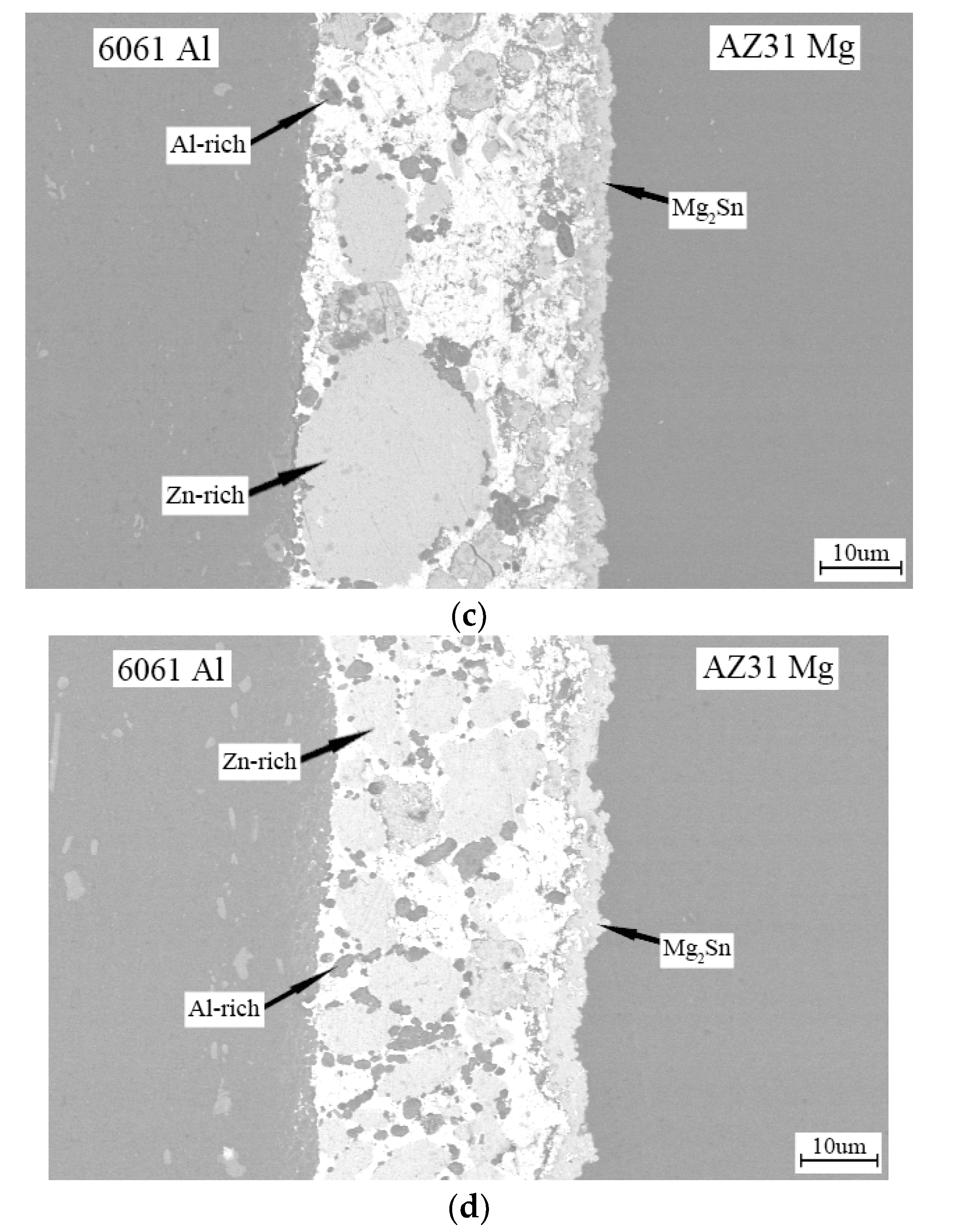
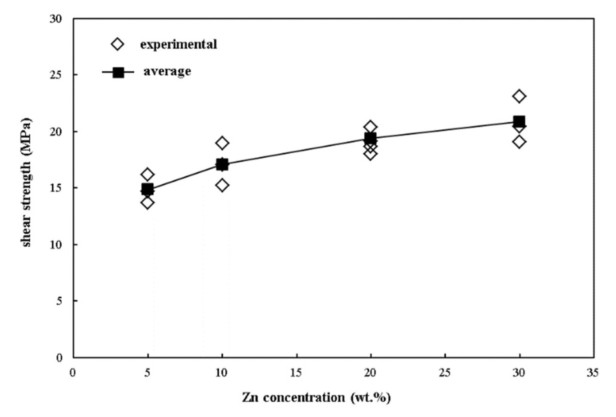
3. Results and Discussion

Cross-sectional SEM micrographs of the AZ31 magnesium/6061 aluminum alloy joints soldered with Sn-xZn (x = 5, 10, 20 and 30 wt.%) filler metals containing rare-earth elements are presented in Figure 2a–d, respectively. Satisfactory bonding interfaces formed in the AZ31 magnesium alloy and the 6061 aluminum alloy joints. No major defects were observed at the joint interfaces. During the soldering process, Mg dissolved irregularly in the solder and formed a bond layer of Mg-Sn intermetallic compounds between the AZ31 magnesium alloy and the solder. The chemical composition of the reaction layer was identified by EDS as Mg:Sn = 63.5:36.5 (at.%), which corresponds to the Mg2Sn phase. The thicknesses of all of the Mg2Sn layers were about 3–5 μm. No oxide film was observed at the interfaces between the 6061 aluminum alloy and solder. According to the binary Sn-Al phase diagram [33], aluminum and tin are completely miscible when the temperature is above the liquidus line. Hence, the dissolution of aluminum into the solder alloy during soldering was violent. When the melted solder was cooled to below the eutectic temperature (228.3 °C) of Sn-Al alloy, the aluminum-rich phase segregated out due to the immiscible binary Sn-Al alloy system. Thus, some Al-rich clusters were found in the solder matrix. The EDS results showed that the Al-rich clusters contained about 97.3 at.% Al and 2.7 at.% Zn. Higher Zn compositions in the solder facilitated the dissolution of aluminum and increased the number of Al-rich clusters in the solder. A large number of Al-rich and coarse Zn-rich phase particles were observed to be embedded in the filler metal of the AZ31 magnesium and 6061 aluminum alloy joints bonded with the Sn-30Zn-0.1RE filler metal.
The bond shear strengths of the 6061 aluminum alloy/AZ31 magnesium alloy joints bonded with Sn-xZn (x = 5, 10, 20 and 30 wt.%) filler metals containing trace rare earth elements were determined to be 14.84, 17.08, 19.39 and 20.86 MPa, respectively. The shear strengths increased significantly with increasing Zn content, as shown in Figure 3.
Figure 4, Figure 5, Figure 6 and Figure 7 show the fractography of the AZ31 magnesium alloy/6061 aluminum alloy joints soldered with Sn-5Zn0.1RE, Sn-10Zn0.1RE, Sn-20Zn0.1RE, and Sn-30Zn0.1RE after shear tests, respectively. The fractographs of joints soldered with Sn-5Zn-0.1RE and Sn-10Zn-0.1RE filler metals indicated that all the fractured surfaces of both the AZ31 magnesium alloy and 6061 aluminum alloy were covered with Mg2Sn intermetallic compound, suggesting that the fractures of the joints occurred mainly in the Mg2Sn intermetallic compound layer. Results indicated that the strength of the interface of 6061 aluminum alloy/solder was higher than that of the Mg2Sn intermetallic compound.
In contrast, the fractured surfaces of both the AZ31 magnesium alloy and the 6061 aluminum alloy joints soldered with the Sn-20Zn-0.1RE and Sn-30Zn-0.1RE filler metals were identified as Sn with Mg2Sn particles. The strengths and the melting points increased with increasing Zn content in the Sn-xZn-0.1RE solders. More Al-rich phase clusters were generated in the solder due to the higher Zn content. Wang et al. [12] studied the joining of magnesium alloy to aluminum alloy with Sn-Zn solders and pointed out that the formation of Al-Sn-Zn solid solution reduces the embrittlement of the AZ31 alloy/solder interface. Thus, the Al-rich solid solution phase inhibited the negative effects of the Mg2Sn.
The shear strengths of the AZ31 magnesium alloy/6061 aluminum alloy joints soldered with Sn-xZn-0.1RE (x = 5, 10, 20, and 30) filler metals after aging at 150 °C for various times are presented in Figure 8. These results indicated that increasing the aging time decreased the joint strength. The cross-sectional SEM micrograph of the AZ31 magnesium/6061 aluminum alloy joints soldered with Sn-xZn (x = 5, 10, 20 and 30 wt.%) filler metals containing rare-earth elements after aging at 150 °C are given in Figure 9, Figure 10, Figure 11 and Figure 12, respectively. The lower shear strength of joints after aging could be attributed to the diffusion of Mg from the base metal and the formation of irregular blocky Mg2Sn intermetallic compounds. The fracture surfaces of AZ31 magnesium alloy/6061 aluminum alloy joints aged at 150 °C are shown in Figure 13, Figure 14, Figure 15 and Figure 16. After aging at 150 °C, fracture occurred similarly to that in the Mg2Sn intermetallic layer of unaged specimens. Before aging, fracture of joints occurred in the interior of the Mg2Sn intermetallic layer. After aging, some failures occurred at the interface of the Mg2Sn intermetallic layer/AZ31 magnesium alloy. During aging, a certain amount of Mg reacted with Sn, causing an embrittlement of the Mg2Sn intermetallic layer.

4. Conclusions

To join the AZ 31 magnesium and 6061 aluminum alloys at 250 °C in air without using flux, low-temperature soldering with Sn-xZn0.1RE (x = 5, 10, 20 and 30 wt.%) filler metals was carried out. Higher Zn compositions in the solder facilitated the dissolution of aluminum and increased the number of Al-rich clusters in the solder. The average shear strength of the joints increased with increases in Zn content. During the soldering process, Mg dissolved irregularly in the solder and formed Mg2Sn intermetallic compounds. After aging at 150 °C, irregular blocky Mg2Sn intermetallic compounds formed and led to decreases in joint strength.

Author Contributions

S.-Y.C. conceived of the presented idea, directed the project and wrote the manuscript. J.-Y.L. and A.-B.W. carried out the experiments and data analysis. Y.-H.H. contributed to literature search, figures, data collection and data interpretation. All authors discussed the results and reviewed the manuscript.

Funding

The authors acknowledge the financial support of this work from the Ministry of Science and Technology of Taiwan R.O.C. under Project No. NSC101-2221-E-224-013.

Conflicts of Interest

The authors declare no conflict of interest.

References

  1. Tamang, S.; Aravindan, S. An investigation on joining of Al6061-T6 to AZ31B by microwave hybrid heating using active braze alloy as an interlayer. J. Manuf. Process. 2017, 28, 94–100. [Google Scholar] [CrossRef]
  2. Borrisutthekul, R.; Miyashita, Y.; Mutoh, Y. Dissimilar material laser welding between magnesium alloy AZ31B and aluminum alloy A5052-O. Sci. Technol. Adv. Mater. 2005, 6, 199–204. [Google Scholar] [CrossRef] [Green Version]
  3. Zhang, J.; Luo, G.; Wang, Y.; Shen, Q.; Zhang, L. An investigation on diffusion bonding of aluminum and magnesium using a Ni interlayer. Mater. Lett. 2012, 83, 189–191. [Google Scholar] [CrossRef]
  4. Li, X.R.; Liang, W.; Zhao, X.G.; Zhang, Y.; Fu, X.P.; Liu, F.C. Bonding of Mg and Al with Mg-Al eutectic alloy and its application in aluminum coating on magnesium. J. Alloys Compd. 2009, 471, 408–411. [Google Scholar] [CrossRef]
  5. Xu, Z.W.; Li, Z.W.; Li, J.P.; Ma, Z.P.; Yan, J.C. Control Al/Mg intermetallic compound formation during ultrasonic-assisted soldering Mg to Al. Ultrason. Sonochem 2018, 46, 79–88. [Google Scholar] [CrossRef] [PubMed] [Green Version]
  6. Liu, L.; Ren, D.; Liu, F. A Review of dissimilar welding techniques for magnesium alloys to aluminum alloys. Materials 2014, 7, 3735–3757. [Google Scholar] [CrossRef] [PubMed]
  7. Adisa, S.B.; Loginova, I.; Khalil, A.; Solonin, A. Effect of Laser Welding Process Parameters and Filler Metals on the Weldability and the Mechanical Properties of AA7020 Aluminium Alloy. J. Manuf. Mater. Process. 2018, 2, 33. [Google Scholar] [CrossRef]
  8. Jacobson, D.M.; Humpston, G.; Sangha, S.P.S. A New Low-Melting-Point Aluminum Braze. Weld. Res. Suppl. 1996, 8, 243s–250s. [Google Scholar]
  9. Tsao, L.C.; Chiang, M.J.; Lin, W.H.; Cheng, M.D.; Chuang, T.H. Effect of zinc additions on the microstructure and melting temperature of Al-Si-Cu filler metals. Mater. Charact. 2002, 48, 341–346. [Google Scholar] [CrossRef]
  10. Gorjan, L.; Blugan, G.; Boretius, M.; De La Pierre, S.; Ferraris, M.; Casalegno, V.; Rizzo, S.; Graule, T.; Kuebler, J. Fracture behavior of soldered Al2O3 ceramic to A356 aluminum alloy and resistance of the joint to low temperature exposure. Mater. Des. 2015, 88, 889–896. [Google Scholar] [CrossRef]
  11. Gorjan, L.; Boretius, M.; Blugan, G.; Gili, F.; Mangherini, D.; Lizarralde, X.; Ferraris, M.; Graule, T.; Igartua, A.; Mendoza, G.; et al. Ceramic protection plates brazed to aluminum brake discs. Ceram. Int. 2016, 42, 15739–15746. [Google Scholar] [CrossRef]
  12. Wang, Z.; Wang, H.Y.; Liu, L.M. Study on low temperature brazing of magnesium alloy to aluminum alloy using Sn-xZn solders. Mater. Des. 2012, 39, 14–19. [Google Scholar] [CrossRef]
  13. Islam, R.A.; Wu, B.Y.; Alam, M.O.; Chan, Y.C.; Jillek, W. Investigations on microhardness of Sn–Zn based lead-free solder alloys as replacement of Sn-Pb solder. J. Alloys Compd. 2005, 392, 149–158. [Google Scholar] [CrossRef]
  14. Garcia, L.R.; Osório, W.R.; Peixoto, L.C.; Garcia, A. Mechanical properties of Sn-Zn lead-free solder alloys based on the microstructure array. Mater. Charact. 2010, 61, 212–220. [Google Scholar] [CrossRef]
  15. Wu, C.M.L.; Yu, D.Q.; Law, C.M.T.; Wang, L. Properties of lead-free solder alloy with rare earth element additions. Mater. Sci. Eng. 2004, R44, 1–44. [Google Scholar] [CrossRef]
  16. Wu, C.M.L.; Law, C.M.T.; Yu, D.Q.; Wang, L. The Wettability and Microstructure of Sn-Zn-RE Alloys. J. Electron. Mater. 2003, 22, 63–69. [Google Scholar] [CrossRef]
  17. Dudek, M.A.; Chawla, N. Oxidation behavior of rare-earth-containing Pb-free solders. J. Electron. Mater. 2009, 38, 210–220. [Google Scholar] [CrossRef]
  18. Wu, C.M.L.; Yu, D.Q.; Law, C.M.T.; Wang, L. The Properties of Sn-9Zn lead-free solder alloys doped with trace rare earth elements. J. Electron. Mater. 2002, 31, 921–927. [Google Scholar] [CrossRef]
  19. Zhang, L.; Cui, J.; Han, J.H.; Guo, Y.H.; He, C.W. Microstructures and properties of SnZn-xEr lead-free solders. J. Rare Earths 2012, 30, 790–793. [Google Scholar] [CrossRef]
  20. Koleňák, R.; Kostolný, I. Study of direct bonding ceramics with metal using Sn2La solder. Adv. Mater. Sci. Eng. 2015, 2015, 1–13. [Google Scholar] [CrossRef]
  21. Koleňák, R.; Šebo, P.; Provazník, M.; Koleňáková, M.; Ulrich, K. Shear strength and wettability of active Sn3.5Ag4Ti(Ce,Ga) solder on Al2O3 ceramics. Mater. Des. 2011, 32, 3997–4003. [Google Scholar] [CrossRef]
  22. Chang, S.Y.; Chuang, T.H.; Yang, C.L. Low temperature bonding of alumina/alumina and alumina/copper in air using Sn3.5Ag4Ti(Ce,Ga) Filler. J. Electron. Mater. 2007, 36, 1193–1198. [Google Scholar] [CrossRef]
  23. Hillen, F.; Pickart-Castillo, D.; Rass, I.J.; Lugscheider, E. Solder alloy and soldering processes for flux–free soldering of difficult-to-wet materials. Weld. Cut. 2000, 52, 162–165. [Google Scholar]
  24. Liu, C.H.; Kim, Y.J.; Chun, D.W.; Kim, G.W.; Chen, R.K. Universal solder for direct bonding and packaging of optical devices. Mater. Lett. 2015, 152, 232–236. [Google Scholar] [CrossRef]
  25. Ramirez, A.G.; Mavoori, H.; Jin, S. Bonding nature of rare-earth-containing lead-free solders. Appl. Phys. Lett. 2002, 80, 398–400. [Google Scholar] [CrossRef]
  26. Smith, R.W. Active solder joining of metals, ceramics and composites. Weld. J. 2001, 10, 30–35. [Google Scholar]
  27. Chang, S.Y.; Tsao, L.C.; Chiang, M.J.; Tung, C.N.; Pan, G.H.; Chuang, T.H. Active soldering of indium tin oxide (ITO) with Cu in air using an Sn3.5Ag4Ti(Ce,Ga) filler. J. Mater. Eng. Perform. 2003, 2, 383–389. [Google Scholar] [CrossRef]
  28. Chang, S.Y. Active Soldering of ZnS-SiO2 Sputtering targets to copper backing plates using an Sn56Bi4Ti(Ce, Ga) filler. Mater. Manuf. Process. 2006, 21, 761–765. [Google Scholar] [CrossRef]
  29. Tsao, L.C. Direct Active Soldering of Micro–arc Oxidized Ti/Ti Joints in air using Sn3.5Ag0.5Cu4Ti(RE) filler. Mater. Sci. Eng. A 2013, 565, 63–71. [Google Scholar] [CrossRef]
  30. Cheng, L.X.; Li, G.Y.; Wang, X.Q.; Li, Z.L.; Wu, Z.Z. Influence of active element Ti on interfacial reaction and soldering strength between Sn3.5Ag4Ti(Ce, Ga) alloy filler and Si substrate. Mater. Sci. Eng. A 2016, 658, 42–49. [Google Scholar] [CrossRef]
  31. Cheng, L.X.; Liu, M.R.; Wang, X.Q.; Yan, B.H.; Li, G.Y. Effect of active element Ti on interfacial microstructure and bonding strength of SiO2/SiO2 joins soldered using Sn3.5Ag4Ti(Ce, Ga) alloy filler. Mater. Sci. Eng. A 2017, 680, 317–323. [Google Scholar] [CrossRef]
  32. Lee, J.Y. Joining of Magnesium Alloys and Aluminum Alloys Using Sn-Zn Aolders. Master’s Thesis, National Yunlin University of Science and Technology, Yunlin County, Taiwan, 2010. [Google Scholar]
  33. Massalski, T.B.; Murray, J.L.; Bennett, L.H.; Baker, H. Binary Alloy Phase Diagrams; American Society for Metal: Metals Park, OH, USA, 1986. [Google Scholar]
Figure 1. Schematic representation of the soldered specimens used for shear testing in this study.
Applsci 09 02655 g001
Figure 2. Cross-sectional SEM micrographs of the AZ31 magnesium/6061 aluminum alloy joints bonded with Sn-xZn-0.1RE filler metals. (a) Sn-5Zn-0.1RE, (b) Sn-10Zn-0.1RE, (c) Sn-20Zn-0.1RE, and (d) Sn-30Zn-0.1RE.
Applsci 09 02655 g002aApplsci 09 02655 g002b
Figure 3. The shear strengths of 6061 aluminum alloy/AZ31 magnesium alloy joints bonded with Sn-xZn-0.1RE filler metals with various Zn contents.
Applsci 09 02655 g003
Figure 4. Fractography of the AZ31 magnesium alloy/6061 aluminum alloy joint bonded with the Sn-5Zn0.1-RE solder. (a) 6061 aluminum alloy side; (b) AZ31 magnesium alloy side.
Applsci 09 02655 g004
Figure 5. Fractography of the AZ31 magnesium alloy/6061 aluminum alloy joint bonded with the Sn-10Zn-0.1RE solder. (a) 6061 aluminum alloy side; (b) AZ31 magnesium alloy side.
Applsci 09 02655 g005
Figure 6. Fractography of the AZ31 magnesium alloy/6061 aluminum alloy joint bonded with the Sn-20Zn-0.1RE solder. (a) 6061 aluminum alloy side; (b) AZ31 magnesium alloy side.
Applsci 09 02655 g006aApplsci 09 02655 g006b
Figure 7. Fractography of the AZ31 magnesium alloy/6061 aluminum alloy joint bonded with the Sn-30Zn-0.1RE solder. (a) 6061 aluminum alloy side; (b) AZ31 magnesium alloy side.
Applsci 09 02655 g007
Figure 8. The shear strengths of the AZ31 magnesium alloy/6061 aluminum alloy joints soldered with Sn-xZn-0.1RE (x = 5, 10, 20, and 30) filler metals after aging at 150 °C for various times.
Applsci 09 02655 g008
Figure 9. Cross-sectional SEM micrographs of the AZ31 magnesium/6061 aluminum alloy joints bonded with the Sn-5Zn-0.1RE filler metal after aging at 150 °C for. (a) 50 h; (b) 100 h
Applsci 09 02655 g009aApplsci 09 02655 g009b
Figure 10. Cross-sectional SEM micrographs of the AZ31 magnesium/6061 aluminum alloy joints bonded with the Sn-10Zn-0.1RE filler metal after aging at 150 °C for (a) 50 h; (b) 100 h.
Applsci 09 02655 g010
Figure 11. Cross-sectional SEM micrographs of the AZ31 magnesium/6061 aluminum alloy joints bonded with the Sn-20Zn-0.1RE filler metal after aging at 150 °C for (a) 50 h; (b) 100 h.
Applsci 09 02655 g011
Figure 12. Cross-sectional SEM micrographs of the AZ31 magnesium/6061 aluminum alloy joints bonded with the Sn-30Zn-0.1RE filler metal after aging at 150 °C for (a) 50 h; (b) 100 h.
Applsci 09 02655 g012aApplsci 09 02655 g012b
Figure 13. Fractographs of the AZ31 magnesium alloy/6061 aluminum alloy joints bonded with the Sn-5Zn-0.1RE filler metal after aging at 150 °C. (a) the 6061 aluminum alloy side after 50 h of aging; (b) the AZ31 magnesium alloy side after 50 h of aging; (c) the 6061 aluminum alloy side after 100 h of aging; (d) the AZ31 magnesium alloy side after 100 h of aging.
Applsci 09 02655 g013aApplsci 09 02655 g013b
Figure 14. Fractographs of the AZ31 magnesium alloy/6061 aluminum alloy joints bonded with the Sn-10Zn-0.1RE filler metal after aging at 150 °C (a) the 6061 aluminum alloy side after 50 h of aging; (b) the AZ31 magnesium alloy side after 50 h of aging; (c) the 6061 aluminum alloy side after 100 h of aging; (d) the AZ31 magnesium alloy side after 100 h of aging.
Applsci 09 02655 g014aApplsci 09 02655 g014b
Figure 15. Fractographs of the AZ31 magnesium alloy/6061 aluminum alloy joints bonded with the Sn-20Zn-0.1RE filler metal after aging at 150 °C. (a) the 6061 aluminum alloy side after 50 h of aging; (b) the AZ31 magnesium alloy side after 50 h of aging; (c) the 6061 aluminum alloy side after 100 h of aging; (d) the AZ31 magnesium alloy side after 100 h of aging.
Applsci 09 02655 g015aApplsci 09 02655 g015b
Figure 16. Fractographs of the AZ31 magnesium alloy/6061 aluminum alloy joints bonded with the Sn-30Zn-0.1RE filler metal after aging at 150 °C. (a) the 6061 aluminum alloy side after 50 h of aging; (b) the AZ31 magnesium alloy side after 50 h of aging; (c) the 6061 aluminum alloy side after 100 h of aging; (d) the AZ31 magnesium alloy side after 100 h of aging.
Applsci 09 02655 g016aApplsci 09 02655 g016b
Table 1. Chemical compositions of the AZ31 magnesium alloy and 6061 aluminum alloys.
AlloyChemical Composition (wt.%)
MgAlZnCrCuSiMn
AZ31 magnesium alloyBal.31 0.0050.020.2
6061 aluminum alloy1.1Bal. 0.120.250.610.01

