Article

Coherent Perfect Absorption Laser Points in One-Dimensional Anti-Parity–Time-Symmetric Photonic Crystals

1
School of Innovation and Entrepreneurship, Xianning Vocational Technical College, Xianning 437100, China
2
Hubei University of Science and Technology, Xianning 437100, China
*
Authors to whom correspondence should be addressed.
These authors contributed equally to this work.
Appl. Sci. 2019, 9(13), 2738; https://doi.org/10.3390/app9132738
Submission received: 13 June 2019 / Revised: 29 June 2019 / Accepted: 2 July 2019 / Published: 6 July 2019
(This article belongs to the Special Issue Novel and Efficient Semiconductor-based Light Sources)

Abstract

:
We investigate the coherent perfect absorption laser points (CPA-LPs) in anti-parity–time-symmetric photonic crystals. CPA-LPs, which correspond to the poles of reflection and transmission, can be found in the parameter space composed of gain–loss factor and angular frequency. Discrete exceptional points (EPs) split as the gain–loss factor increases. The CPA-LPs sandwiched between the EPs are proved to be defective modes. The localization of light field and the bulk effect of gain/loss in materials induce a sharp change in phase of the reflection coefficient near the CPA-LPs. Consequently, a large spatial Goos–Hänchen shift, which is proportional to the slope of phase, can be achieved around the CPA-LPs. The study may find great applications in highly sensitive sensors.

1. Introduction

In photonic crystals (PCs), one can manipulate photons in the same way as electrons in semiconductors. By modulating the refractive indices of dielectric materials, it forms periodic distribution in space and obtains special optical properties. PCs, which are microstructures of wavelength-scale, have photonic bandgaps, that is, light with frequency within the bandgaps cannot pass through the PCs [1,2,3,4]. There are natural photonic crystals, such as opals and butterfly wings. What is more, we can achieve specific optical functions by synthesizing PCs. PCs can also realize localization of light field [5,6,7,8], unidirectional transmission [9,10], directional cloaking [11], solitons [12,13,14], and other functions [15,16,17,18,19]. Otherwise, PCs are used to control photon flows, which can realize the miniaturization and integration of photonic devices [20,21,22,23,24].
It is often necessary to modulate the refractive index of material in the study on PCs. In the past, it mainly focused on the modulation of the real part of the refractive index, while in recent years, the regulation of the imaginary part of the refractive index has gradually attracted people’s attention. The imaginary part of the refractive index represents the loss or gain of material. Loss seems to be an unfavorable factor, which causes energy attenuation, so it should be minimized in device design. People usually reduce the energy loss during the propagation of light through the mode matching in appropriate materials and structures, or compensate the loss of devices through gain. According to quantum mechanics, a system is non-Hermitian if there is loss or gain. By using the similarity between the paraxial equation of electromagnetic field propagation under the slowly varying envelope approximation [25] and the Schrödinger equation of quantum mechanics, the concept of non-Hermite can be extended to the regime of optics [26,27]. Relevant studies have contributed to the proposal of non-Hermitian photonics, which has become a hot topic in optics in recent years. In a non-Hermitian optical system, by simultaneously modulating the real part and the imaginary part of the refractive index of the material, single-mode laser [28], loss-induced transparency [29], and optical field localization [30] can be achieved.
The parity–time (PT)-symmetric Hamiltonian can have real spectra, which extends quantum mechanics into a new research field [31,32]. PT-symmetric Hermiticity is a new concept and PT symmetry in electronic systems has been widely concerned and aroused a lot of discussion [33]. PT symmetry is also of great theoretical and applied value in optics and other related regimes [34,35,36,37,38,39,40,41]. The use of PT potentials in optics has been recently reviewed by Longhi [42], which provides a good background for non-Hermitian properties. The pioneering work to use gain and loss in optics to implement PT-symmetric Hamiltonian was Ruschhaupt et al. [43]. The work presented belongs to a set of explorations of non-Hermitian symmetries beyond PT, a vast and promising field that is just beginning to develop. It will surely provide many important results and applications [44]. The gain in the photon system can be obtained by nonlinear two-wave mixing [45], or Ge/Cr doped fiber [46], while the loss can be achieved by acoustic modulator [47]. Thus, optics has the natural advantage of being used to explore all sorts of non-Hermite predictions that used to be verified difficult in quantum mechanics. However, studies on non-Hermitian photonics have shown that loss and gain, satisfied with PT symmetry, provide a new degree of freedom for the system, which can effectively control photons and generate new optical effects, such as unidirectional reflectionless resonance, which can be used to prepare chip-level semiconductor lasers [48].
Anti-PT-symmetric systems, in which the refractive index of material obeys n(x) = −n*(−x), have been proposed and attracted much attention [49,50,51]. Many interesting phenomena are found in anti-PT-symmetric systems, such as flat broadband light transport [50], and chiral mode conversion [52]. Actually, anti-PT symmetry belongs to a more fundamental symmetry called charge-conjugation symmetry [53,54], which consists of two sublattices. The study on asymmetric coupled systems shows that the topological bound states can be generated via a degeneracy induced by charge-conjugation symmetry [53,55]. Moreover, the topological bound modes can be selectively pumped due to their special energy spectrum [54,56], which can be further utilized to enhance the lasing performance with improved single-mode property, higher slope efficiencies, and robustness against perturbation [57,58,59].
In this work, we investigate the coherent perfect absorption laser points (CPA-LPs) (CPA laser states for which such systems can behave simultaneously as a laser oscillator, emitting outgoing coherent waves, and as a CPA (coherent perfect absorber), absorbing incoming coherent waves) [60,61] in the anti-PT-symmetric PCs. We show that CPA-LPs arise in the parameter space composed of gain–loss factor, and angular frequency. The CPA-laser states, which are sandwiched in splitting exceptional points (EPs), are confirmed to be substantially defective modes. We also discuss the crossing and anti-crossing properties of the eigenvalues of scattering matrix around the CPA-LPs. We further explore the phase of reflection coefficient, and demonstrate the singularity of phase around the CPA-LPs. In the end, we illustrate the application of the singular phase near the CPA-LPs, and induce large spatial Goos–Hänchen (GH) shift, which can be utilized for highly sensitive sensing.

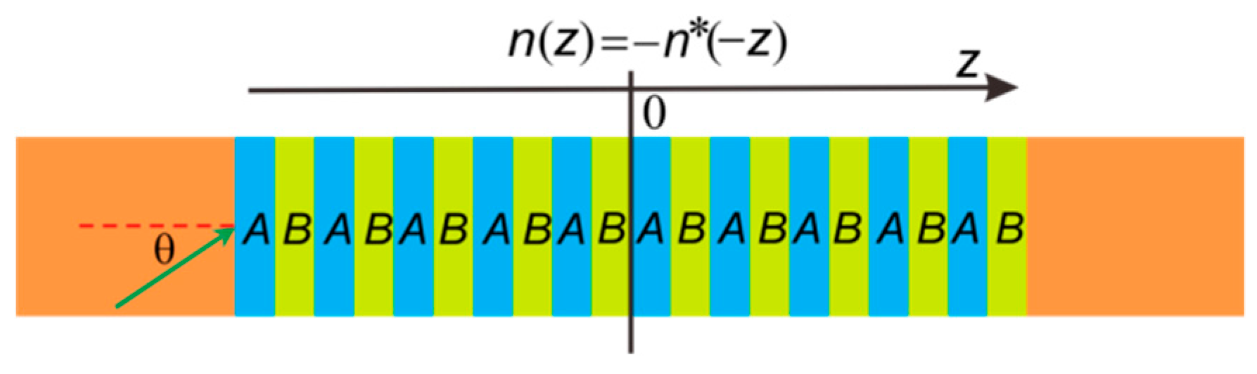
2. One-Dimensional Anti-PT-Symmetric PCs

Figure 1 shows the schematic of the one-dimensional anti-PT-symmetric PCs. The dielectrics A and B are arranged alternatively to form the periodic structure comprising periodic unit cells (thickness: 2d). The structure can also be viewed as a Bragg grating, denoted by (AB)N, where N is defined as the Bragg periodic number. The refraction index in each unit cell is real and given by n(z) = na as 0 < z < d and n(z) = nb as d < z < 2d. Using the transfer matrix method (TMM), we can relate the electromagnetic fields at the two interfaces of a homogeneous medium by [62]
( E l H l ) = ( cos φ l i η l sin φ l i η l sin φ l cos φ l ) ( E l + 1 H l + 1 ) ,
where φl = 2πdl(εl − sin2θ)1/2/λ, dl is the thickness of the lth layer transmission dielectric, θ is the incident angle, and El, Hl, El+1, and Hl+1 are the electromagnetic field intensity at two interfaces of homogeneous dielectric, respectively. For transverse electric (TE) waves, ηl = (ε00)1/2(εl − sin2θ)1/2, and for transverse magnetic (TM) waves, ηl = εl00)1/2/(εl − sin2θ)1/2. The structure’s total transfer matrix is M = ΠMl = [m11, m12, m21, m22], where Ml is the corresponding transfer matrix of the lth layer dielectric. Then, the transmission and reflection coefficients can be obtained by the transfer matrix elements
t = 2 η 1 m 11 η 1 + m 12 η 1 η 2 N + 1 + m 21 + m 22 η 1 ,
r = m 11 η 1 + m 12 η 1 η 2 N + 1 m 21 m 22 η 2 N + 1 m 11 η 1 + m 12 η 1 η 2 N + 1 + m 21 + m 22 η 2 N + 1 ,
where η2N+1 = η1 = η0 is the vacuum resistivity of light at the input and output ports, respectively. The transmittance T is identified as T = tt* = It/Ii, where It and Ii are the incident and transmitted intensities, respectively.

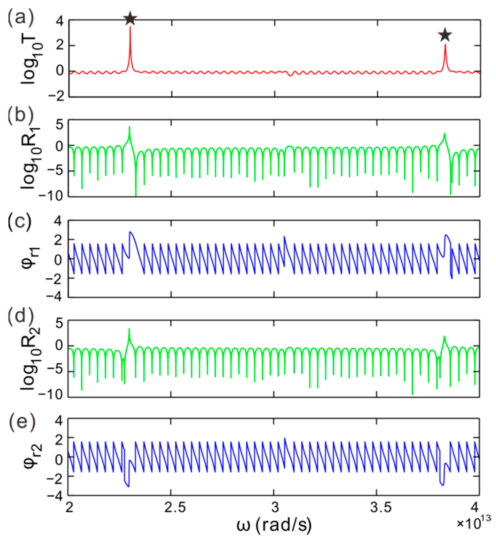
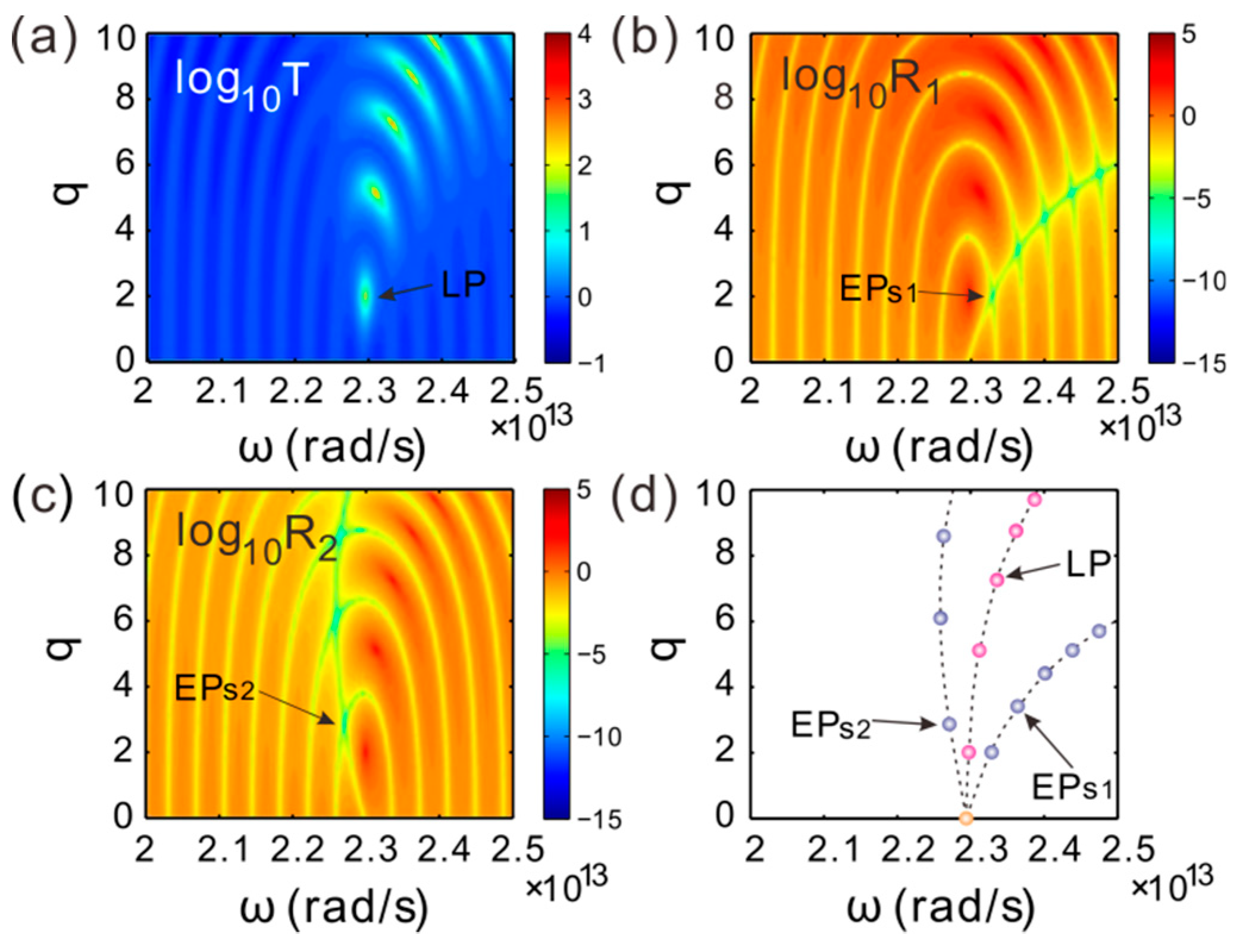
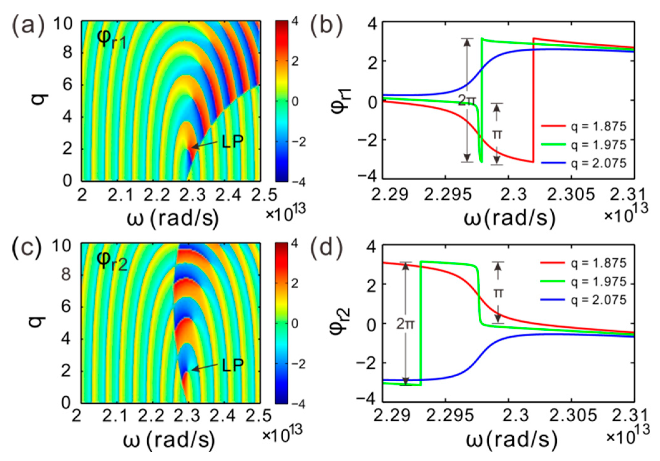
3. CPA-LPs and EPs Splitting

As an example, we consider a one-dimensional anti-PT-symmetric PC consisting of 20 periodic unit cells, viz. N = 20, embedded in a homogeneous background, such as in air, shown in Figure 1. The parameters are d = 125 μm, n = 1, ∆n = 0.5, θ = 5°. In our numerical model, we have neglected these material nonlinearity and dispersion as a simplification. Now, we calculate the transmission and reflection spectra as the TM wave obliquely impinges upon the anti-PT-symmetric PCs from the left and right sides. Figure 2a plots the transmittance spectrum, where we observe two resonant states associated with sharp transmission peaks T = 3.01 × 10³ and 1.27 × 10² in the curve marked by black stars, respectively locating at ω = 2.3 × 10¹³, and 3.8 × 10¹³ rad/s.
Figure 2b gives the reflectance spectrum for light incident from the left. It shows that there are also two maxima in the curve of R1. The positions of the peaks are identical in the transmittance and reflectance spectra. This phenomenon demonstrates that two CPA-laser states may exist around the two maxima. The values of the nadirs in R1 equal nearly to zero, considering the limit of calculation accuracy. The reflection coefficient is represented by r = |r|exp(iφ), where φ is the phase change of reflection beam. The phase of the reflection coefficient varies with the angular frequency as shown in Figure 2c. There are π jumps in phase at the nadirs of R1. When the reflectivity is zero, the phase uncertainty of the reflection coefficient is caused. It is notable that, around the peaks of the transmittance and reflectance, the reflection coefficient phase changes dramatically with the change of angular frequency. The dramatic change in phase may induce novel physical effects. For light incident from the right, Figure 2d gives the reflectance spectrum T2, which is not identical with the spectrum R1. Therefore, the reflection is anisotropic for light incident from the left and right sides. However, the corresponding frequencies of the two maxima in R2 are identical with the values in R1. The phase of the reflection coefficient is shown in Figure 2e. The two reflection coefficient phase curves do not seem to coincide superficially. However, these two curves are really the same if we subtract these π jumps in phase at the zero points in the curves of R1 and R2.
In the parameter space composed of the gain–loss factor and angular frequency, Figure 3a gives the transmittance of light as light incident from the left or right. We can see that there are some poles in the parameter space such as at CPA-LP1 (qLP1 = 1.975, ωLP1 = 2.3 × 10¹³ rad/s), and so on. The extreme values of the poles approve them to be CPA-laser states, so we call the poles in the parameter space CPA-LPs. The CPA-laser state is a defective mode or resonant state. The output energy of the laser state is provided by the gain in the dielectrics. Figure 3b plots the reflectance of light incident from the left. The maxima of reflectance coincide with the maxima of transmittance in the parameter space, which identifies that the poles of reflection and transmission correspond to the CPA-LPs as well. Otherwise, we find some discrete EPs denoted by EPs1 in parameter space. The zero point of reflection is confirmed to be EP based on the scattering matrix S = [t, r1; r2, t] [63]. The eigenvalues and eigenvectors of S-matrix are given by λ1,2 = t ± (r1r2)1/2, and (r11/2, ± r21/2), respectively. The two eigenvectors (λ1,2) coalesce at (r1r2)1/2 = 0 signifying the EPs of the eigenvalues—or, to be more precise, the EPs originate from r1 or r2 = 0.
As light impinges upon the structure from the right, Figure 3c provides the reflectance. One can see that there are also some CPA-LPs and EPs2 in the parameter space. The position of the CPA-LPs in parameter space does not change for light incident from the left or right. But the EPs are located at the left side of the CPA-LPs. To demonstrate the relation between the CPA-LPs and EPs, we give the phase transition shown in Figure 3d as the gain–loss factor increases. The EPs1 and EPs2 split, and the interval of splitting EPs increases with the increase of the gain-loss factor. The CPA-LPs, which are proved to be the defective modes, are sandwiched between the EPs1 and EPs2.
In the parameter space composed of angular frequency ω and gain–loss factor q, one of the CPA-LP emerge as the gain–loss factor approaches qLP1 = 1.975. To verify the CPA-LPs in the anti-PT-symmetric PCs, Figure 4a,b depicts the real part Re(λ1,2) and imaginary part Im(λ1,2) of the eigenvalues λ1,2 of S-matrix. It shows that the eigenvalues degenerate at the CPA-LPs as the angular frequency changes. It is the unique property of CPA-LPs usually utilized for confirming CPA-LP in non-Hermitian systems. In the vicinity of the CPA-LP, the curves of the imaginary part are crossing, while the curves of the real part are anti-crossing [52]. The CPA-LPs are connected with the surface mode localized at the gain–loss boundary. Figure 4c gives the electric field intensity distribution of the CPA-LP1 at (qLP1 = 1.975, ωLP1 = 2.3 × 10¹³ rad/s). It demonstrates that most of the light field power is located in the center layers and is strongly restrained at the interfaces of dielectrics. Along the z-axis, the field exponentially decays as it departs from the center.
As light is incident from the left, Figure 5a illustrates the reflection coefficient phase, φr1, in parametric space, where the angular frequency and gain–loss gain can be modified in the vicinity of the CPA-LP1. The phase dislocates around the CPA-LP1, which is unique for the CPA-LPs in non-Hermitian systems [64]. The singularity in phase indicates that the phase should abruptly change once the parameters undergo a little variation.
Figure 5b plots the coefficient phase, φr1, versus the angular frequency for several different gain–loss factors. The sampling gain–loss factors are q = 1.875, 1.975, and 2.075, which distribute around the qLP1, respectively. There is a hop point in the phase curve as q = 1.875, and the phase difference is −2π. Neglecting the meaningless phase difference at the hop point, the curve is actually continuous with a negative slope. The phase change can approximately reach π in a phase variation range around qLP1 as the gain–loss factor q < qLP1. The phase experiences a π abrupt jump at ωLP1 as q = qLP1. Comparably, the phase change can nearly reach −π around ωLP1 with a positive slope as q > qLP1.
For light incident from the right, as depicted in Figure 5c, there is also a phase dislocation in φr2 existing in the vicinity of the CPA-LP1. Contrary to φr1, the position of the phase hop points in the parametric space does not change. Figure 5d plots the reflection coefficient phase φr2, which varies with the angular frequency for several different gain–loss factors around the CPA-LP1. An abrupt phase change also occurs as q = qLP1. A π phase roughly falls off in a variation range of gain–loss factor about qLP1 as q < qLP1, but a π phase climbs as q > qLP1. The localization of light field and the bulk effect of gain/loss in material may induce the sharp change in phase of the reflection coefficient.

4. Large Spatial GH Shift Around CPA-LPs

GH shift is the lateral shift and angular deviation of the reflected beam, relative to the position predicted by geometrical optics [65]. How to design, and find, appropriate structures or materials to increase GH shift is the key problem to be considered at present. With reference to the lattice structure of solid crystals, people put forward the concept of PCs, which provide a new approach to solve the above problem. At the bandgap edge of the PCs, there is large GH shift [66], and the optical field localization of the defect PCs can also induce large GH shift [62].
The spatial GH shift relates to the phase of the reflection coefficient, and is proportional to the slope of reflection phase in accordance with Δ = –dφr1, r2/dky [65], where ky = ksinθ and k = λ/2π. For another example, the CPA-LPs are singular points in the phase of the reflection coefficient, which is to say that the phase dislocates at the CPA-LPs. Therefore, a large spatial GH shift may be induced around the CPA-LPs. Figure 6a plots the phase of the reflection coefficient in the parameter space. The focusing region is separated into two parts labeled I and II, respectively. The spatial GH shifts are negative in part I, while it is positive in part II. Except for the CPA-LP1, the spatial GH shifts approximate to zero along the dotted line. The negative and positive polarities of GH shift convert at the CPA-LP1, approving the singularity of the GH shift.
Figure 6b plots the spatial GH shift versus angular frequency for the gain–loss factor q = 1.875. One can see that the GH shift is positive, and a peak appears around the CPA-LP1. Figure 6c gives the GH shift for q = 1.975. It shows that there is also a maximum in the curve, but the peak becomes sharper and narrower when the gain–loss factor is closer to qLP1. However, as q = 2.075, the spatial GH shift is negative, and there is a valley in the curve shown in Figure 6d. For the three special gain–loss factors, the corresponding maxima of GH shift are 3.4 × 10³, 1.13 × 10⁵, and −3.25 × 10³ times of the incident wavelength around ωLP1. Here, we show that a large GH shift in a bulk multilayer structure and the imaginary part of refractive index play an important role in realizing CPA-LPs of the system. The spatial GH shift is highly sensitive to the refractive index of dielectric and angular frequency of incident light, as shown in Figure 6b–d around the CPA-LP. However, the applications in sense at the exceptional point appear to be rather challenging, such as the effect of fluctuations and noise [67,68,69].

5. Conclusions

In conclusion, we have studied the CPA-LPs in one-dimensional anti-PT-symmetric PCs. By varying the gain–loss factor and angular frequency, CPA-LPs and discrete EPs can be found in the parameter space. The CPA-LPs which are defective modes are located between the splitting EPs. The light field of the CPA-LPs are constrained at the interfaces of dielectrics, and mainly distributed at the center of structure. The localization of light field and gain/loss in material generate the singularity of reflection coefficient phase around the CPA-LPs, at which point the phase dislocates. Therefore, a large spatial GH shift is induced near the CPA-LPs, and the maximum GH shift approaches the magnitude of 105λ. The study paves the way for development in highly sensitive sensors.

Author Contributions

Software, H.W. and P.Z.; investigation, W.K.; writing—original draft preparation, W.K.; writing—review and editing, P.Z., and D.Z.; funding acquisition, Z.L. and D.Z. project administration, D.Z.

Funding

National Natural Science Foundation of China (NSFC) (61575148); Natural Science Foundation of Hubei Province (2015CFA040, 2016CFB515); Educational Commission of Hubei Province (D20172803); Humanities and Social Science Project of Hubei Education Department (18Q164); Colleges and Universities of National Innovation and Entrepreneurship Training Plan (201710927006Z, 201810927011).

Conflicts of Interest

The authors declare no conflicts of interest.

References

  1. Joannopoulos, J.D.; Villeneuve, P.R.; Fan, S. Photonic crystals: Putting a new twist on light. Nature 1997, 386, 143. [Google Scholar] [CrossRef]
  2. Zhao, D.; Ke, S.; Hu, Y.; Wang, B.; Lu, P. Optical bistability in parity-time-symmetric dielectric multilayers incorporated with graphene. J. Opt. Soc. Am. B 2019, 36, 1731–1737. [Google Scholar] [CrossRef]
  3. Zhao, D.; Liu, F.; Meng, P.; Wen, J.; Xu, S.; Li, Z.; Zhong, D. Reflection enhancement and giant lateral shift in defective photonic crystals with graphene. Appl. Sci. 2019, 9, 2141. [Google Scholar] [CrossRef]
  4. Yablonovitch, E. Photonic crystals: Semiconductors of light. Sci. Am. 2001, 285, 46–55. [Google Scholar] [CrossRef]
  5. Soukoulis, C.M. Photonic Crystals and Light Localization in the 21st Century; Springer Science and Business Media: Dordrecht, The Netherlands, 2012; Volume 563. [Google Scholar]
  6. Mingaleev, S.F.; Kivshar, Y.S. Nonlinear transmission and light localization in photonic-crystal waveguides. J. Opt. Soc. Am. B 2002, 19, 2241–2249. [Google Scholar] [CrossRef] [Green Version]
  7. Zhao, D.; Wang, Z.Q.; Long, H.; Wang, K.; Wang, B.; Lu, P.X. Optical bistability in defective photonic multilayers doped by graphene. Opt. Quant. Electron. 2017, 49, 163. [Google Scholar] [CrossRef]
  8. Zhao, D.; Zhong, D.; Hu, Y.; Ke, S.; Liu, W. Imaginary modulation inducing giant spatial Goos-Hänchen shifts in one-dimensional defective photonic lattices. Opt. Quant. Electron. 2019, 51, 113. [Google Scholar] [CrossRef]
  9. Cakmak, A.O.; Colak, E.; Serebryannikov, A.E.; Ozbay, E. Unidirectional transmission in photonic-crystal gratings at beam-type illumination. Opt. Express 2010, 18, 22283–22298. [Google Scholar] [CrossRef] [Green Version]
  10. Khanikaev, A.B.; Steel, M.J. Low-symmetry magnetic photonic crystals for nonreciprocal and unidirectional devices. Opt. Express 2009, 17, 5265–5272. [Google Scholar] [CrossRef]
  11. Vasić, B.; Gajić, R. Self-focusing media using graded photonic crystals: Focusing, Fourier transforming and imaging, directive emission, and directional cloaking. J. Appl. Phys. 2011, 110, 053103. [Google Scholar] [CrossRef]
  12. Xu, S.L.; Xue, L.; Belić, M.R.; He, J.R. Spatiotemporal soliton clusters in strongly nonlocal media with variable potential coefficients. Nonlinear Dyn. 2017, 87, 827–834. [Google Scholar] [CrossRef]
  13. Xu, S.L.; Petrovi, N.; Belić, M.R.; Deng, W. Exact solutions for the quintic nonlinear Schrödinger equation with time and space. Nonlinear Dyn. 2017, 84, 251–259. [Google Scholar] [CrossRef]
  14. Xu, S.L.; Petrović, N.; Belić, M.R. Exact solutions of the (2+1)-dimensional quintic nonlinear Schrödinger equation with variable coefficients. Nonlinear Dyn. 2015, 80, 583–589. [Google Scholar] [CrossRef]
  15. Meng, P.; Zhao, D.; Zhong, D.; Liu, W. Topological plasmonic modes in graphene-coated nanowire arrays. Opt. Quant. Electron. 2019, 51, 156. [Google Scholar] [CrossRef]
  16. Wang, Z.; Wang, B.; Long, H.; Wang, K.; Lu, P. Surface plasmonic lattice solitons in semi-infinite graphene sheet arrays. J. Lightwave Technol. 2017, 35, 2960–2965. [Google Scholar] [CrossRef]
  17. Ke, S.; Zhao, D.; Liu, Q.; Wu, S.; Wang, B.; Lu, P. Optical imaginary directional couplers. J. Lightwave Technol. 2018, 36, 2510–2515. [Google Scholar] [CrossRef]
  18. Li, Z.P.; Xu, Z.M.; Qu, X.P.; Wang, S.B.; Peng, J.; Mei, L.H. Fabrication of nanopore and nanoparticle arrays with high aspect ratio AAO masks. Nanotechnology 2017, 28, 095301. [Google Scholar] [CrossRef] [PubMed]
  19. Chen, S.; Guo, Q.; Xu, S.; Belic, M.R.; Zhao, Y.; Zhao, D.; He, J. Vortex Solitons in Bose-Einstein Condensates with Spin-Orbit Coupling and Gaussian Optical Lattices. Appl. Math. Lett. 2019, 92, 15–21. [Google Scholar] [CrossRef]
  20. Hu, Y.; Zhang, S.; Xie, M.; Zeng, H. GeSe monolayer semiconductor with tunable direct band gap and small carrier. Appl. Phys. Lett. 2015, 107, 122107. [Google Scholar] [CrossRef]
  21. Ni, H.; Li, M.; Hu, Y.; Mao, C.; Xue, L.; Zeng, H.; Yan, Z.; Wu, Y.; Zheng, C. Two-dimensional SnSe/GeSe van der Waals heterostructure with strain-tunable electronic and optical properties. J. Phys. Chem. Solids 2019, 131, 223–229. [Google Scholar] [CrossRef]
  22. Kinyua, D.M.; Long, H.; Xing, X.; Njoroge, S.; Wang, K.; Wang, B.; Lu, P. Gigahertz acoustic vibrations of Ga-doped ZnO nanoparticle array. Nanotechnology 2019, 30, 305201. [Google Scholar] [CrossRef] [PubMed]
  23. Li, Z.; Xu, Z.; Qu, X.; Wang, S.; Peng, J. Pattern transfer of hexagonal packed structure via ultrathin metal nanomesh masks for formation of Si nanopore arrays. J. Alloys Compd. 2017, 695, 458–461. [Google Scholar] [CrossRef]
  24. Li, Z.; Wang, G.; Li, Z.; Cheng, Z.; Zhou, G.; Li, S. Flexible transparent electrodes based on gold nanomeshes. Nanoscale Res. Lett. 2019, 14, 132. [Google Scholar] [CrossRef] [PubMed]
  25. Longhi, S. Quantum-optical analogies using photonic structures. Laser Photon. Rev. 2009, 3, 243–261. [Google Scholar] [CrossRef]
  26. Zhen, B.; Hsu, C.W.; Igarashi, Y.; Lu, L.; Kaminer, I.; Pick, A.; Chua, S.; Joannopoulos, J.D.; Soljačić, M. Spawning rings of exceptional points out of Dirac cones. Nature 2015, 525, 354–358. [Google Scholar] [CrossRef]
  27. Feng, L.; Zhu, X.; Yang, S.; Zhu, H.; Zhang, P.; Yin, X.; Wang, Y.; Zhang, X. Demonstration of a large-scale optical exceptional point structure. Opt. Express 2014, 22, 1760–1767. [Google Scholar] [CrossRef]
  28. Peng, B.; Ozdemir, S.K.; Rotter, S.; Yilmaz, H.; Liertzer, M.; Monifi, F.; Bender, C.M.; Nori, F.; Yang, L. Loss-induced suppression and revival of lasing. Science 2014, 346, 328–332. [Google Scholar] [CrossRef] [Green Version]
  29. Guo, A.; Salamo, G.J.; Duchesne, D.; Morandotti, R.; Christodoulides, D.N. Observation of PT-symmetry breaking in complex optical potentials. Phys. Rev. Lett. 2009, 103, 093902. [Google Scholar] [CrossRef]
  30. Zhu, X.F. Defect states and exceptional point splitting in the band gaps of one-dimensional parity-time lattices. Opt. Express 2015, 23, 22274–22284. [Google Scholar] [CrossRef]
  31. Bender, C.M.; Boettcher, S. Real spectra in non-Hermitian Hamiltonians having PT symmetry. Phys. Rev. Lett. 1998, 80, 5243–5246. [Google Scholar] [CrossRef]
  32. Hatano, N.; Nelson, D.R. Localization transitions in non-Hermitian quantum mechanics. Phys. Rev. Lett. 1996, 77, 570–573. [Google Scholar] [CrossRef] [PubMed]
  33. Lee, Y.C.; Hsieh, M.H.; Flammia, S.T.; Lee, R.K. Local PT symmetry violates the no-signaling principle. Phys. Rev. Lett. 2014, 112, 130404. [Google Scholar] [CrossRef] [PubMed]
  34. Cheng, J.X.; Xu, S.L.; Belić, M.R.; Li, H.; Zhao, Y.; Deng, W.W.; Sun, Y.Z. Multipole solitons in a cold atomic gas with a parity-time symmetric potential. Nonlinear Dyn. 2019, 95, 2325–2332. [Google Scholar] [CrossRef]
  35. Bender, C.M. PT symmetry in quantum physics: From a mathematical curiosity to optical experiments. Europhysics News 2016, 47, 17–20. [Google Scholar] [CrossRef]
  36. Zhao, D.; Liu, W.W.; Ke, S.L.; Liu, Q.J. Large lateral shift in complex dielectric multilayers with nearly parity–time symmetry. Opt. Quant. Electron. 2018, 50, 323. [Google Scholar] [CrossRef]
  37. Ke, S.; Liu, Q.; Zhao, D.; Liu, W. Spectral discrete diffraction with non-Hermitian coupling. J. Opt. Soc. Am. B 2018, 35, 2387–2393. [Google Scholar] [CrossRef]
  38. Ke, S.; Liu, J.; Liu, Q.; Zhao, D.; Liu, W. Strong absorption near exceptional points in plasmonic wave guide arrays. Opt. Quant. Electron. 2018, 50, 318. [Google Scholar] [CrossRef]
  39. Ke, S.; Zhao, D.; Liu, Q.; Liu, W. Adiabatic transfer of surface plasmons in non-Hermitian graphene waveguides. Opt. Quant. Electron. 2018, 50, 393. [Google Scholar] [CrossRef]
  40. Xu, S.L.; Zhao, Y.; Petrović, N.Z.; Belić, M.R. Spatiotemporal soliton supported by parity-time symmetric potential with competing nonlinearities. EPL 2016, 115, 14006. [Google Scholar] [CrossRef]
  41. Xu, S.L.; Petrović, N.; Belić, M.R.; Hu, Z.L. Light bullet supported by parity-time symmetric potential with power-law nonlinearity. Nonlinear Dyn. 2016, 84, 1877–1882. [Google Scholar] [CrossRef]
  42. Longhi, S. Parity-time symmetry meets photonics: A new twist in non-Hermitian optics. EPL 2018, 120, 64001. [Google Scholar] [CrossRef]
  43. Ruschhaupt, A.; Delgado, F.; Muga, J.G. Physical realization of PT-symmetric potential scattering in a planar slab waveguide. J. Phys. Math. Gen. 2005, 38, L171–L176. [Google Scholar] [CrossRef]
  44. Ruschhaupt, A.; Dowdall, T.; Simón, M.A.; Muga, J.G. Asymmetric scattering by non-Hermitian potentials. EPL 2018, 120, 20001. [Google Scholar] [CrossRef]
  45. Rüter, C.E.; Makris, K.G.; El-Ganainy, R.; Christodoulides, D.N.; Segev, M.; Kip, D. Observation of parity–time symmetry in optics. Nat. Phys. 2010, 6, 192–195. [Google Scholar] [CrossRef]
  46. Feng, L.; Xu, Y.L.; Fegadolli, W.S.; Lu, M.; Oliveira, J.E.B.; Almeida, V.R.; Chen, Y.; Scherer, A. Experimental demonstration of a unidirectional refectionless parity-time metamaterial at optical frequencies. Nat. Mater. 2013, 12, 108–113. [Google Scholar] [CrossRef] [PubMed]
  47. Regensburger, A.; Bersch, C.; Miri, M.A.; Onishchukov, G.; Christodoulides, D.N.; Peschel, U. Parity-time synthetic photonic lattices. Nature 2012, 488, 167–171. [Google Scholar] [CrossRef] [PubMed]
  48. Feng, L.; El-Ganainy, R.; Ge, L. Non-Hermitian photonics based on parity–time symmetry. Nat. Photon. 2017, 11, 752–762. [Google Scholar] [CrossRef]
  49. Ge, L.; Türeci, H.E. Antisymmetric PT-photonic structures with balanced positive- and negative-index materials. Phys. Rev. A 2013, 88, 053810. [Google Scholar] [CrossRef]
  50. Yang, F.; Liu, Y.; You, L. Anti-PT symmetry in dissipatively coupled optical systems. Phys. Rev. A 2017, 96, 053845. [Google Scholar] [CrossRef]
  51. Ke, S.; Zhao, D.; Liu, J.; Liu, Q.; Liao, Q.; Wang, B.; Lu, P. Topological bound modes in anti-PT-symmetric optical waveguide arrays. Opt. Express 2019, 27, 13858. [Google Scholar] [CrossRef]
  52. Zhang, X.; Jiang, T.; Sun, H.; Chan, C.T. Dynamically encircling an exceptional point in anti-PT-symmetric systems: asymmetric mode switching for symmetry-broken states. arXiv 2018, arXiv:1806.07649. [Google Scholar]
  53. Malzard, S.; Poli, C.; Schomerus, H. Topologically protected defect states in open photonic systems with non-Hermitian charge-conjugation and Parity-Time symmetry. Phys. Rev. Lett. 2015, 115, 200402. [Google Scholar] [CrossRef] [PubMed]
  54. Ge, L. Symmetry-protected zero-mode laser with a tunable spatial profile. Phys. Rev. A 2017, 95, 023812. [Google Scholar] [CrossRef] [Green Version]
  55. Kunst, F.K.; Edvardsson, E.; Budich, J.C.; Bergholtz, E.J. Biorthogonal bulk-boundary correspondence in non-Hermitian systems. Phys. Rev. Lett. 2018, 121, 026808. [Google Scholar] [CrossRef] [PubMed]
  56. Poli, C.; Bellec, M.; Kuhl, U.; Mortessagne, F.; Schomerus, H. Selective enhancement of topologically induced interface states in a dielectric resonator chain. Nat. Commun. 2015, 6, 6710. [Google Scholar] [CrossRef] [PubMed]
  57. Parto, M.; Wittek, S.; Hodaei, H.; Harari, G.; Bandres, M.A.; Ren, J.; Rechtsman, M.C.; Segev, M.; Christodoulides, D.N.; Khajavikhan, M. Edge-mode lasing in 1D topological active arrays. Phys. Rev. Lett. 2018, 120, 113901. [Google Scholar] [CrossRef]
  58. Harari, G.; Bandres, M.A.; Lumer, Y.; Rechtsman, M.C.; Chong, Y.D.; Khajavikhan, M.; Christodoulides, D.N.; Segev, M. Topological insulator laser: Theory. Science 2018, 359, eaar4003. [Google Scholar] [CrossRef] [Green Version]
  59. Bandres, M.A.; Wittek, S.; Harari, G.; Parto, M.; Ren, J.; Segev, M.; Christodoulides, D.N.; Khajavikhan, M. Topological insulator laser: Experiments. Science 2018, 359, eaar4005. [Google Scholar] [CrossRef] [Green Version]
  60. Savoia, S.; Castaldi, G.; Galdi, V.; Alú, A.; Engheta, N. Tunneling of obliquely incident waves through PT-symmetric epsilon-near-zero bilayers. Phys. Rev. B 2014, 89, 085105. [Google Scholar] [CrossRef]
  61. Shramkova, O.V.; Tsironis, G.P. Scattering properties of PT-symmetric layered periodic structures. J. Opt. 2016, 18, 105101. [Google Scholar] [CrossRef]
  62. Zhao, D.; Ke, S.; Liu, Q.; Wang, B.; Lu, P. Giant Goos-Hänchen shifts in non-Hermitian dielectric multilayers incorporated with graphene. Opt. Express 2018, 26, 2817–2828. [Google Scholar] [CrossRef] [PubMed]
  63. Liu, Q.; Wang, B.; Ke, S.; Long, H.; Wang, K.; Lu, P. Exceptional points in Fano-resonant graphene metamaterials. Opt. Express 2017, 25, 7203–7212. [Google Scholar] [CrossRef] [PubMed]
  64. Ke, S.; Wang, B.; Qin, C.; Long, H.; Wang, K.; Lu, P. Exceptional points and asymmetric mode switching in plasmonic waveguides. J. Lightwave Technol. 2016, 34, 5258–5262. [Google Scholar] [CrossRef]
  65. Merano, M. Optical beam shifts in graphene and single-layer boron-nitride. Opt. Lett. 2016, 41, 5780–5783. [Google Scholar] [CrossRef] [PubMed] [Green Version]
  66. Wang, L.G.; Zhu, S.Y. Giant lateral shift of a light beam at the defect mode in one-dimensional photonic crystals. Opt. Lett. 2006, 31, 101–103. [Google Scholar] [CrossRef] [PubMed]
  67. Mortensen, N.A.; Gonçalves, P.A.D.; Khajavikhan, M.; Christodoulides, D.N.; Tserkezis, C.; Wolff, C. Fluctuations and noise-limited sensing near the exceptional point of parity-time-symmetric resonator systems. Optica 2018, 5, 1342–1346. [Google Scholar] [CrossRef] [Green Version]
  68. Wolff, C.; Tserkezis, C.; Mortensen, N.A. On the time evolution at a fluctuating exceptional point. arXiv 2018, arXiv:1810.08390. [Google Scholar] [CrossRef]
  69. Hayenga, W.E.; Ren, J.; Parto, M.; Wu, F.; Hokmabadi, M.P.; Wolff, C.; Khajavikhan, M. Direct generation of tunable orbital angular momentum beams in microring lasers with broadband exceptional points. arXiv 2019, arXiv:1903.10108. [Google Scholar]
Figure 1. Schematic of the one-dimensional anti-parity–time (PT)-symmetric photonic crystals (PCs), where the complex refractive indices are distributed in n(z) = n(−z). For the primitive unit cell layers A and B, the thickness is d = 125 μm and the complex refractive indices are n + ∆n + 0.01qi, and n∆n + 0.01qi, respectively. The imaginary part is positive for gain material and negative for loss material.
Applsci 09 02738 g001
Figure 2. The calculated spectra for the anti-PT-symmetric PCs. The transmission spectrum T (a), the reflection spectrum R1 (b), and the phase of reflection coefficient (c) for light incident from the left, respectively. The reflection spectrum R2 (d), and the phase of reflection coefficient (e) for light incident from the right, respectively. The gain-loss factor q = 2.
Applsci 09 02738 g002
Figure 3. (ac) The transmittance and reflectance varying with the gain–loss factor and angular frequency for light incident from the left and right, respectively. (d) Phase transition as the strength of gain–loss modulation increases from zero. Discrete splitting EPs are located at the blue dots. CPA-LPs are located at the purple dots.
Applsci 09 02738 g003
Figure 4. (a,b) The real part and imaginary part of eigenvalues for scattering matrix varying with the angular frequency around the LP for q = qLP. (c) The electric field intensity (|Ez|2) distribution at the CPA-LP.
Applsci 09 02738 g004
Figure 5. (a,c) The phase of reflection coefficient varying with the gain–loss factor and angular frequency for light incident from the left and right, respectively. (b,d) The phase curves versus the angular frequency for several specific refractive indices around the CPA-LP1 for light incident from the left and right, respectively.
Applsci 09 02738 g005
Figure 6. (a) The spatial Goos–Hänchen (GH) shift in the vicinity of CPA-LP1. The GH shift is negative in part I, while it is positive in part II. It has rescaled the result by taking logarithm log10|∆/λ| for clarity. (bd) The spatial GH shift varying with the angular frequency for several given gain–loss factor q = 1.875, 1.975, and 2.075, respectively.
Applsci 09 02738 g006

