1. Introduction
Conductivity, as a parameter of ferromagnetic materials, can serve as an index to sort different materials, and evaluate heat treatment condition or measure the stress of mechanical parts [
1,
2,
3]. Due to the advances in electromagnetic nondestructive evaluation, pulsed eddy current (PEC) testing has become a feasible and preferred technique for measuring conductivity of materials in recent years [
4,
5]. However, for ferromagnetic samples, the measurement of conductivity is affected by the inhomogeneity of tested samples and the confounding cross-sensitivity to conductivity and permeability, which is undesirable in precision PEC testing [
6,
7]. Especially, the influence of permeability is complex and irregular. On the other hand, correspondingly, the permeability of ferromagnetic material will change when the environmental magnetic field changes. Therefore, reducing the permeability effect or the influence of environmental magnetic field in the measurement of electrical conductivity of ferromagnetic samples is an important problem to be solved in PEC testing. It is important and meaningful to improve the detection accuracy of conductivity of ferromagnetic samples.
In PEC testing, the measurements of conductivity and permeability have been studied by many scholars in recent years. Adewale et al. [
8] decoupled the influence of permeability and conductivity in PEC measurements and the contributions of the electromagnetic properties (permeability and conductivity) were analyzed with a view to isolate the influence of these two properties. It was found that the conductivity effects are prominent in the rising edge of the transient response and the permeability effects are prominent in the stable phase of the transient response. Chen et al. [
4] studied the electrical conductivity measurement of ferromagnetic metallic materials using the PEC technique. In the measurement of conductivity, an inverse problem method based on a PEC analytical model was proposed to determine the conductivity and permeability of ferromagnetic plates. Dziczkowski et al. [
9] described the method of determining the equivalent parameters of the coil, a scaling method for a conductivity meter based on the elimination of liftoff on conductivity results, and a proposition for an effective method to measure the conductivity of rough elements. Lu et al. [
1,
10] found a conductivity lift-off invariance phenomenon and proposed an inverse problem method to determinate the conductivity and permeability of ferrite metallic plates. Wang et al. [
2] proposed an eddy current measurement method to determinate electrical conductivity of samples, which indicated that the logarithm of phase signature of impedance change basically varies linearly with electrical conductivity. Yu et al. [
11] observed a conductivity invariance phenomenon of eddy current non-destructive testing (NDT), and used it to estimate the magnetic permeability of metals without the influence of its conductivity. Ye et al. [
12] proposed a novel approach based on decay time (DT) using PEC and a highly sensitive magnetoresistive (MR) sensor in conductivity measurement of materials. The results indicate that the DT parameter is linearly correlated with material conductivity allowing it to be used for estimating the conductivity from the PEC measurement. According to the above studies, it is found that the conductivity measurements of ferromagnetic samples with a permeability effect are rarely studied by using PEC testing when permeability changes. These works also revealed that the change of PEC signals caused by conductivity and permeability is indistinguishable in the measurement of ferromagnetic samples. In other words, when the conductivity is measured, the influence of permeability can not be reduced or eliminated in PEC signals. Thus, it is important and significant to reduce the influence of permeability on PEC signals, and accurately measure the conductivity of ferromagnetic samples when permeability changes.
It is known that liftoff point of intersection (LOI), as a desirable signal feature, is independent of liftoff distance [
13]. The LOI is a common intersection point of PEC signals when liftoff distance changes. For the permeability effect on PEC signals, a similar method can be considered in the conductivity measurement to reduce the influence of permeability. Thus, similarly, a common intersection invariance point feature is needed in PEC signals of ferromagnetic samples for reducing the permeability effect when sample permeability changes or the environmental magnetic field changes. Therefore, in the measurement of conductivity, it is important and significant to propose a method to obtain a permeability invariance (PI) feature for reducing permeability effect or environmental magnetic field influence.
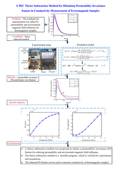
The main contribution of this paper is that a thrice subtraction method is proposed to obtain a PI point feature in PEC signals of ferromagnetic samples for reducing the permeability effect or environmental magnetic field influence. Correspondingly, the availability of the thrice subtraction method and the obtained PI feature is analyzed and discussed. The rest of this paper is organized as follows: in
Section 2 the PEC analytical model is formulated from a harmonic eddy current model, the thrice subtraction method is introduced in
Section 3, the simulation results are analyzed in
Section 4, in
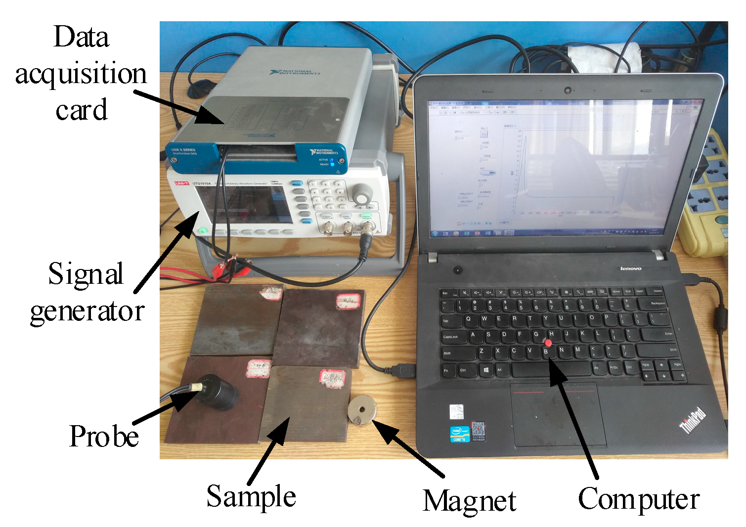
Section 5 the experiments are performed for verifying the simulation results and finally,
Section 6 presents the concluding remarks.
2. Formulation of the PEC Analytical Model
The PEC analytical model, as an effective tool, has been used to analyze the change of PEC signals caused by thickness, conductivity and permeability [
4,
14]. According to previous studies, it can be found that it is very difficult to directly construct a PEC analytical model. However, on the other hand, it is simpler to construct a PEC analytical model based on the harmonic eddy current analytical model. It is known that a periodic pulse signal can be expressed as a Fourier series of trigonometric functions. Therefore, in this paper, the PEC analytical model is reconstructed through using the harmonic eddy current analytical model. The main process is shown in
Figure 1.
In the process of constructing the PEC analytical model, a pulse voltage signal
serves as an excitation signal of the coil sensor. The difference PEC signal
is the voltage change of the coil sensor when a plate is tested. The harmonic eddy current responses
and
in the frequency domain are the basis of the PEC model construction, which have been built in previous studies [
15,
16]. The case for the coil sensor above a conductive plate was considered, as illustrated in
Figure 2. The PEC probe was an air-core cylindrical coil. The plate under research was assumed to be linear, homogeneous and isotropic. The electrical conductivity, permeability and thickness of the measured metallic plate are denoted as
,
and
, respectively, where
(
μ0 is the permeability of the vacuum,
is the relative permeability of the metallic plate). An artificial magnetic insulation boundary was placed at
.
Based on the harmonic eddy current response and spectral pulse signals, the difference PEC response can be formulated by performing Kirchhoff’s Law in the frequency domain. It signifies that the algebraic sum of the voltages of the coil sensor is always equal to zero in a closed loop, which can be expressed as
. Correspondingly, the difference PEC response in the frequency domain can be obtained. Where
and
are the voltage and impedance signal of coil sensor when a plate is tested,
and
are the voltage and impedance signal of the coil sensor when the coil sensor is in air, the voltage signal
and the impedance signal
serve as a reference signal,
is the difference PEC response between the detection signal
Uplate and reference signal
,
is the current of coil sensor,
is the impedance change response when a plate is tested. Correspondingly, the difference PEC response in the frequency domain can be expressed as
where
denotes the Fourier transform of pulse voltage signal
,
,
.
By using inverse Fourier transform (IFT), the difference PEC signal in the time domain can be expressed as
Based on the results, a numerical calculation program can be written in MATLAB software (MTLAB R2014a, Math Works, Inc, Natick, Massachusetts, United States, 2014). Correspondingly, some scientific explanations can be verified by numerical method.
In Equation (1), when the air-core coil is excited by harmonic excitation [
15], the impedance change of air-core coil can be written as
On the other hand, for the case of the air-core coil in air [
15], the impedance can be expressed as
In Equation (3), the
can be expressed as
where
,
denotes the number of the coil turns,
,
are the outer and inner radius of the coil,
denotes the height of the coil,
is the
positive root of the Bessel function
,
is the
order Bessel function of the first kind,
is a constant related to the conductivity, permeability and thickness of measured metallic plates,
.
In order to obtain the difference PEC response for simulating transient induced voltage, the periodic pulse signal is applied. Combined with the superposition principle and inverse Fourier transform, the PEC transient response can be reconstructed from the harmonic eddy current response [
17,
18]. For the
T-periodic pulse, the formula can be expressed as
where,
is the time constant,
is the step function,
is the amplitude value of excitation current,
is the excitation time,
is the excitation period.
3. Thrice Subtraction Method
By analyzing previous research ideas [
13,
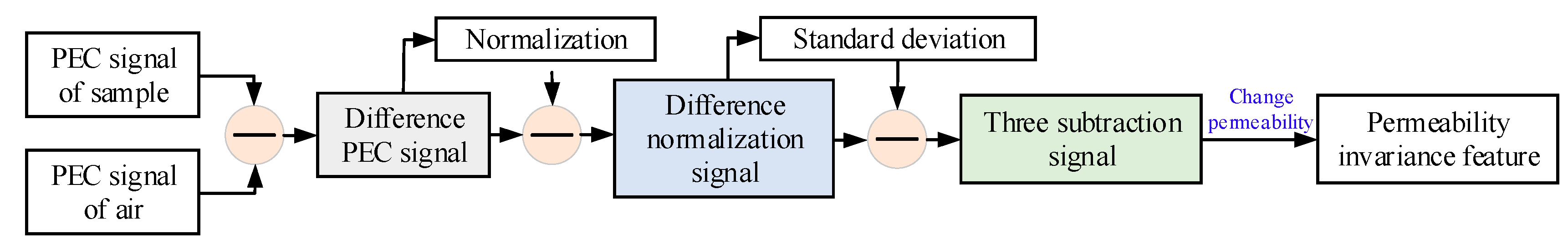
19], a thrice subtraction method was proposed to obtain a PI feature for reducing the effect of permeability change. The thrice subtraction method included three subtraction steps and the operating process is shown in
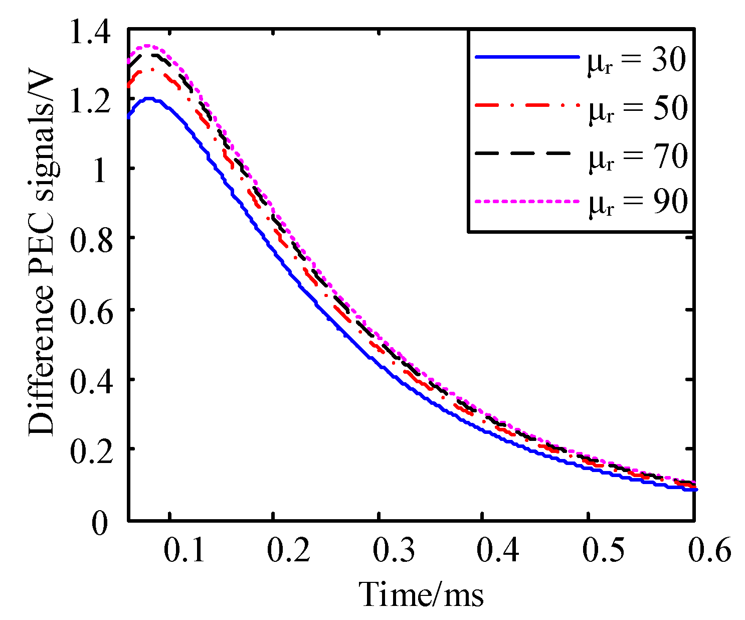
Figure 3. The first subtraction was implemented to eliminate the effect of PEC signal from air. A difference PEC signal was obtained after the subtraction process. Then, the normalization signal of the difference PEC signal was obtained and the second subtraction was performed between the difference PEC signal and its normalization signal, which was used to amplify the variation of the difference PEC signal. Next, the standard deviation of the difference normalization signal was calculated and the third subtraction was implemented, which was used to reduce the effect of permeability. Finally, the PI feature could be extracted from thrice subtraction signals when permeability changed. The detailed steps are described below.
First, the subtraction between PEC signals of sample and air is implemented to obtain the difference PEC signal. The subtraction process can be shown as
where,
is the PEC signal of sample,
is the PEC signal of air.
Second, the subtraction between the difference PEC signal and its normalization signal is performed to obtain the difference normalization signal. The difference normalization signal can be formulated as
where,
denotes the normalization signal of the difference PEC signal,
denotes the maximum value of the difference PEC signal.
Then, the third subtraction between the difference normalization signal and its standard deviation is calculated to obtain the thrice subtraction signal. The thrice subtraction signal can be expressed as
where,
denotes the standard deviation of the difference normalization signal.
By changing the permeability of samples, the different thrice subtraction signals can be obtained and the PI feature can be extracted by mutual subtraction between them as
Finally, by solving Equation (10), the amplitude and time of the PI feature can be obtained. It is easy to think that the common point of both different signals, called the PI feature point, is unaffected by the change in permeability. In other words, the PI feature is immune to the permeability effect.


