Article

Efficient Transmit Delay Calculation in Ultrasound Coherent Plane-Wave Compound Imaging for Curved Array Transducers

1
Department of Electronic Engineering, Sogang University, Seoul 04107, Korea
2
Department of Biomedical Engineering, Sogang University, Seoul 04107, Korea
*
Author to whom correspondence should be addressed.
Appl. Sci. 2019, 9(13), 2752; https://doi.org/10.3390/app9132752
Submission received: 11 March 2019 / Revised: 21 June 2019 / Accepted: 4 July 2019 / Published: 8 July 2019
(This article belongs to the Special Issue Advanced Ultrasound Technology for Medical Application)

Abstract

:

Featured Application

Monitoring of microvasculature in abdomen applications (e.g., kidney and liver).

Abstract

The recently introduced plane-wave compounding method based on multiple plane-wave excitation has enabled several new applications due to its high frame rate (>1000 Hz). In this paper, a new efficient transmit delay calculation method in plane-wave compound imaging for a curved array transducer is presented. In the proposed method, the transmit delay is only calculated for a steering angle of 0° and is shifted along the element of the transducer to obtain other transmit delays for different steering angles. To evaluate the performance of the proposed method, the computational complexity was measured for various transmission conditions. For the number of elements and plane-wave excitations of 128 and 65, respectively, the number of operations was substantially decreased in the proposed method compared with the conventional method (256 vs. 8320). The benefits of the proposed method were demonstrated with phantom and in vivo experiments, where coherent plane-wave compounding with 65 excitations provided larger CR and CNR values compared to nine excitations (−22.5 dB and 2.7 vs. −11.3 dB and 1.9, respectively). These results indicate the proposed method can effectively reduce the computational complexity for plane-wave compound imaging in curved array transducers.

1. Introduction

In conventional medical ultrasound imaging, numerous focused ultrasound beams are utilized to scan a region of interest (ROI) [1]. Since only a single or few image scanlines are formed in each beam transmission, approximately one-hundred insonifications are generally required to reconstruct an entire image frame. Considering the speed of sound in body tissue is approximately 1540 m/s [2], the maximum frame rate is fundamentally limited (e.g., 40 frames per second when scanning a depth of 15 cm with 128 beam transmissions). In other words, the total number of ultrasound beams per frame must be reduced in order to increase the frame rate.
For high-frame-rate imaging, various beam profiles and transmission schemes have been presented, such as broad-beam [3], multiline [4], and plane [5,6,7] or diverging beam [8] transmissions. The plane-wave imaging technique shown in Figure 1, which utilizes an unfocused wave to interrogate the entire ROI in a single transmission, has especially revealed the potential for very high-frame-rate imaging. In addition, by coherently compounding multiple frames of images acquired using several plane-waves with various steering angles, the spatial resolution, contrast, and signal-to-noise ratio (SNR) of plane-wave imaging can be enhanced while attaining a high enough frame rate for the applications [9]. As a result, a number of new applications have been enabled. For example, tissue elasticity mapping by monitoring a shear wave propagating through the medium using a very high frame rate [10,11,12], very sensitive color or power Doppler imaging using a very large number of data samples obtained within a short acquisition time [13,14,15,16], stable or very fast monitoring of contrast agents [17,18], and super-resolution imaging based on the localization of contrast bubbles [19] were all made possible by the plane-wave compounding technique.
Although plane-wave compound imaging has mainly been utilized in linear array imaging, it can be applied to curved array imaging (e.g., curvilinear, endocavitary, and microconvex) for high-resolution abdominal ultrasonography [20]. However, curved array imaging generally requires a larger number of plane-waves to obtain the wider ROI compared to linear array imaging since the region inside of the compounded plane waves (i.e., the area that is fully synthesized) is narrow [6]. Moreover, in terms of transmit delay calculation for curved array imaging, a nonlinear delay for each element of the curved array (e.g., 128-elements) should be individually calculated due to the structurally curved shape (the elements are aligned along the radius of the transducer), whereas a linear delay can be simply calculated by adding up the increment in a linear array transducer. Therefore, as the number of transmissions per frame increases, more computations are required to calculate the transmit delays of the plane beams and reconstruct the images in curved array imaging. These increments in terms of computational complexity can be considered a challenge for real-time imaging. In addition, various plane-wave imaging applications, such as shear wave elastography and microvascular imaging, commonly utilize an ROI map to visualize biological function in the finite range of interest regions [5]. By changing the position and size of the ROI map along the axial and lateral directions, the transmit delays corresponding to the number of plane-wave transmissions and the degree of steering angles must be adjusted to provide uniform image quality and field of view [9]. These transmit delays can be pre-calculated and stored in the look-up table (LUT). However, since the number of transmission cases varies depending on the target application, it is advantageous to recalculate the transmit delays in real time. Moreover, for the fast image reconstruction in the real-time system, a parallel beamformer architecture based on graphics processing units (GPUs) can be adopted [21] and the operations required for calculating transmit delays should be considered as well. Therefore, an efficient transmit delay calculation method is necessary to overcome these challenges.
In this paper, a new efficient transmit delay calculation method, in which the number of operations does not increase proportionally to the number of plane-wave transmissions, is proposed. By applying the proposed method, the total number of operations for a transmit delay calculation can be substantially reduced. The proposed method was evaluated using the total number of delay calculations and the corresponding computation time in various conditions, i.e., a different number of transmit elements or number of plane-waves.

2. Materials and Methods

2.1. Plane-Wave Compound Imaging

Unlike the conventional method of ultrasound imaging where a line-by-line scanning method utilizing a number of focused ultrasound beams is applied, several tilted plane-waves are used in plane-wave compound imaging. The frames acquired using plane-waves of various steering angles are summed to achieve synthetic transmit focusing as shown in Figure 2.
Using this technique, a very high frame rate can be achieved due to the reduced number of transmissions per frame. In addition, uniform resolution can be achieved throughout the ROI as shown in Figure 3.
Although plane-waves can be easily generated using a linear array transducer due to the straight arrangement of the elements, since a linear shape is not suitable for scanning wide and deep areas, a curved array transducer should be chosen for a broader application of plane-wave imaging. To generate a plane beam from a curved array, the time delay for each array element must be calculated properly by considering the shape of the array, which is an arc.

2.2. Conventional Transmit Delay Calcuation

Figure 4 is a geometrical model of the transmit delay calculation. To excite a plane-wave from a curved array transducer, the transmit time delay for each array element can be calculated by the following:
τ T X ( θ P W , n ) = R · cos ( θ P W θ e l e , n ) / c   ( n = 1 , 2 , , N e l e )
where R is the radius of the transducer, θ P W is the steering angle of the plane-wave, θ e l e , n is the angle between the direction vector of the nth element and the z-axis, N e l e is the number of array elements, and c is the speed of sound [20].
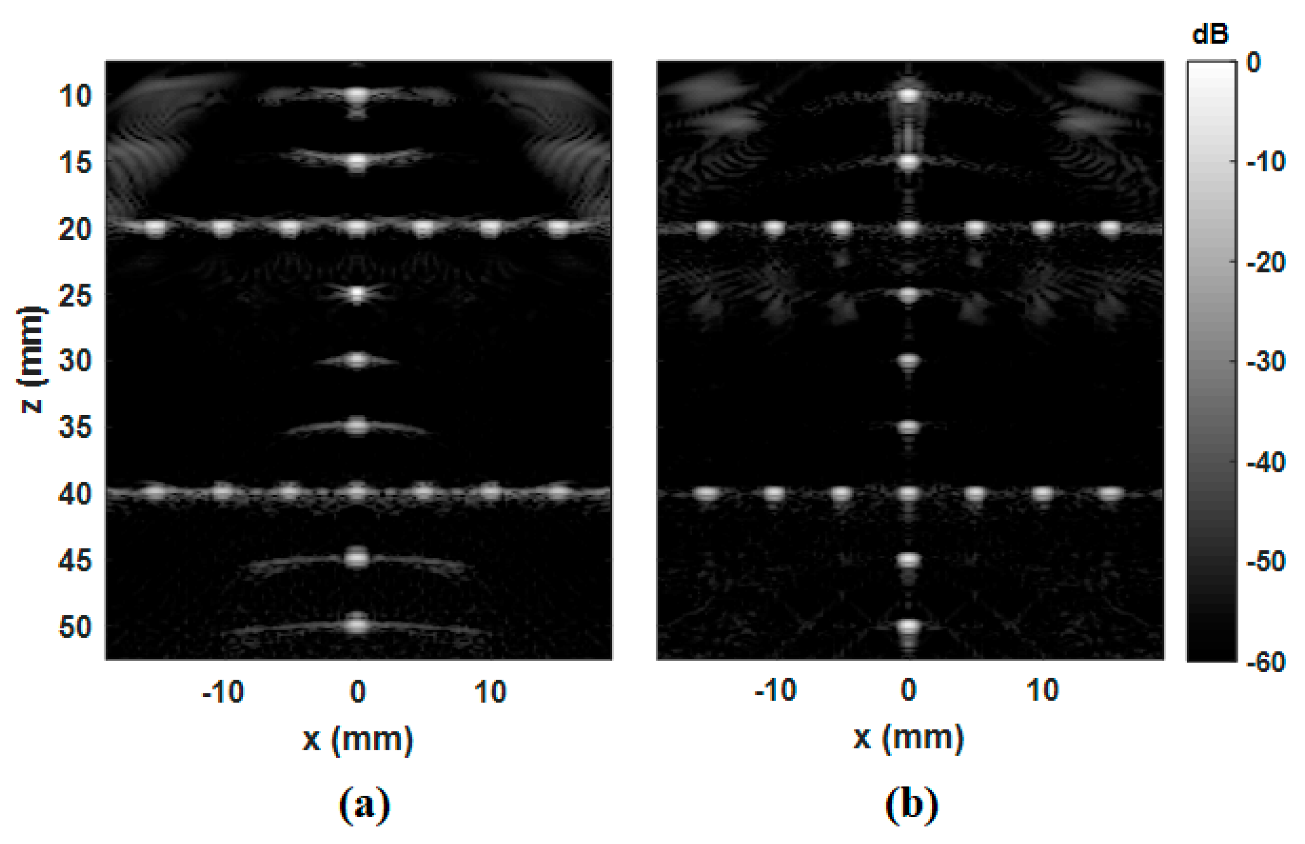
As indicated in Equation (1), the number of cosine operations is proportional to the number of elements and the number of steering angles. In addition, since curved array imaging has a larger ROI than linear array imaging, a wider range of steering angles is required to interrogate the entire sector-shaped ROI. Therefore, more plane-waves are required to suppress artifacts resulting from grating lobes or side lobes, leading to an increase in the number of calculations, as shown in Figure 5.
Figure 5a,b show the difference in the number of artifacts between two images acquired using nine plane-waves and 65 plane-waves, respectively, when the scan angle of the ROI is 75.54 degrees.

2.3. Efficient Transmit Delay Calculation

To reduce the total number of computations for transmit delay calculation, we propose reusing the delay values calculated earlier. This method can be applied when the steering angle θ P W is an integer multiple of the angle between the direction vectors of two adjacent elements. Under this condition, Equation (1) can be developed as follows:
τ T X ( θ P W , n ) = τ T X ( k · d θ , n ) = R · cos ( k · d θ θ e l e , n ) / c = R · cos ( k · d θ ( ( n 1 ) · d θ + θ e l e , 1 ) ) / c = R · cos ( 0 ( ( n k 1 ) · d θ + θ e l e , 1 ) ) / c = τ T X ( 0 , n k )   ( k = k m i n , k m i n + 1 , , k m a x )
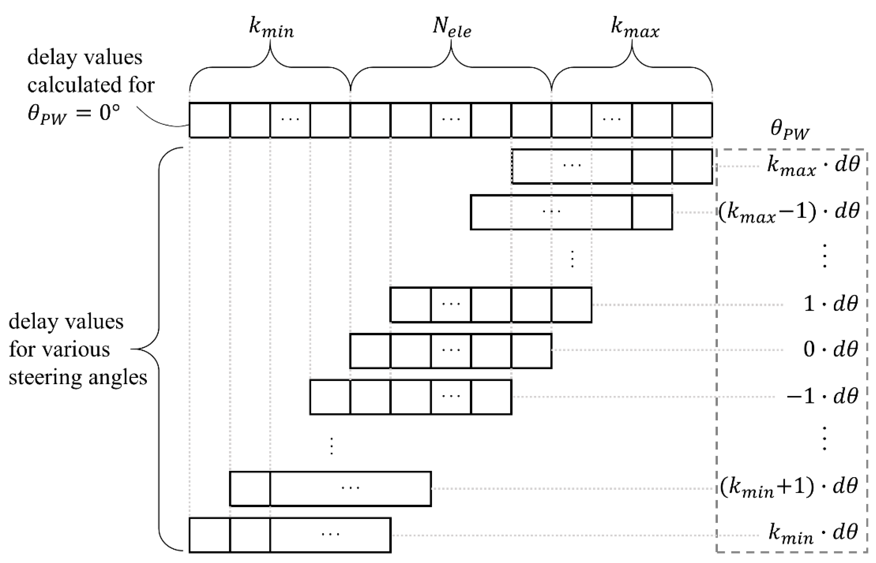
where d θ is the angle between the direction vectors of two adjacent elements, namely, d θ = θ e l e , n + 1 θ e l e , n , and k m i n and k m a x are the minimum and the maximum values of an integer k ( k m i n < 0 < k m a x ). As a result of the equality in Equation (2), the transmit delay of the nth-element for θ P W = k · d θ is equal to the delay of the (n-k)th-element for θ P W = 0. By applying the equality to the delay calculation, the delays for θ P W = k · d θ can be obtained from the delays for θ P W = 0 as shown in Figure 6. In addition, the steering angles of plane-waves are selected with symmetry [11] so that k m i n = k m a x for simplicity.

3. Results and Discussion

In the proposed method, the total number of operations is not affected by the number of transmit plane-waves but is related to the maximum value of k because additional delays to be shifted must also be calculated. Therefore, the total number is ( N e l e + 2 · k m ) in the proposed method while the total number is ( N e l e × N P W ) in the conventional method, where N P W is the number of transmit plane-waves with different steering angles, and k m is related to θ P W and d θ as follows:
θ P W = k · d θ k m = θ P W m a x
where θ P W m a x is the maximum steering angle.
Since k m is not related to N e l e and N P W , the computational complexity of the proposed method can be determined by the variable k m irrespective of N P W . To assess the efficiency of the proposed method, the total number of computations for the conventional method and the proposed method were calculated for various conditions and summarized in Table 1.
As listed in Table 1, the proposed method has a substantially lower total number of computations than the conventional method (e.g., 256 vs. 8320, respectively, with k m = 64 when the number of elements and transmit plane-waves are 128 and 65, respectively; these are the same conditions shown in Figure 5b). Although the optimal value of k m is 64 in the condition, the value can be set higher to facilitate a larger range of steering angles, increasing the lateral resolution at the outer part of the image.
Moreover, in the case of k m > N e l e to increase steering angles, θ P W m a x can be exceeded for the maximum scan angle of the ROI; it does not allow for improved image quality due to the defined scanning area and the inherent element directivity function [20]. Therefore, the proposed method will be at least N p w / 3 times more efficient than the conventional method when k m is lower than N e l e (i.e., the total number of computation is N e l e + 2 · k m 3 × N e l e ).
To evaluate the real-time performance of the proposed method, the transmit delay calculation was implemented on a NVIDIA Computer Unified Device Architecture (CUDA) platform (GTX 660 Ti, NVIDIA, Santa Clara, CA, USA) for every case listed in Table 1 and the computational time was measured as summarized in Table 2.
As listed in Table 2, for N e l e of 128, N P W of 65, and k m of 64, the proposed method yielded 8.4 ± 0.7 μs compared to the conventional method, 78.6 ± 0.5 μs. The computational efficiency of the proposed method was significantly improved in a larger number of transmit beams. Therefore, the efficient transmit delay calculation method in curved arrays will improve the performance of real-time implementation for ultrafast curved array applications. For example, a shear wave elastography technique based on plane-wave transmission has already been commercialized and it is widely used in a clinical setting (e.g., liver fibrosis evaluation) [11,23]. In shear wave elastography, the position and size of the ROI map visualizing tissue elasticity are changed according to the position and size of the interest area (i.e., lesion) [24,25]. In that case, e.g., the number of plane-waves and the degree of steering angles, can be adjusted for providing comparable image quality and field-of-view [9]. Therefore, transmit delays need to be recalculated while the transmission parameters are adjusted, and the proposed method can improve the computational efficiency. Moreover, it is useful for supporting emerging applications where high image quality is necessary by increasing the number of plane-wave transmission.
To demonstrate the feasibility of the proposed method in terms of image quality enhancement, a tissue-mimicking phantom (040GSE, CIRS Inc., Norfolk, VA, USA) was scanned using a C5-2 curved array transducer and a programmable ultrasound research platform (Vantage 128, Verasonics Inc., Redmond, WA, USA) with 9 or 65 plane-wave insonifications. In addition, in vivo abdominal data were obtained from a healthy volunteer under Institutional Review Board (IRB) approval. The contrast ratio (CR) and contrast-to-noise ratio (CNR) [26] were also measured in the phantom study as the following:
CR = 20 log 10 ( μ c y s t μ b k g d )
CNR = | μ c y s t μ b k g d | σ c y s t 2 + σ b k g d 2
where μ c y s t and μ b k g d are the mean intensities of the image in the cyst and the background regions, respectively, and σ c y s t and σ b k g d are the corresponding standard deviations of the intensities in the regions.
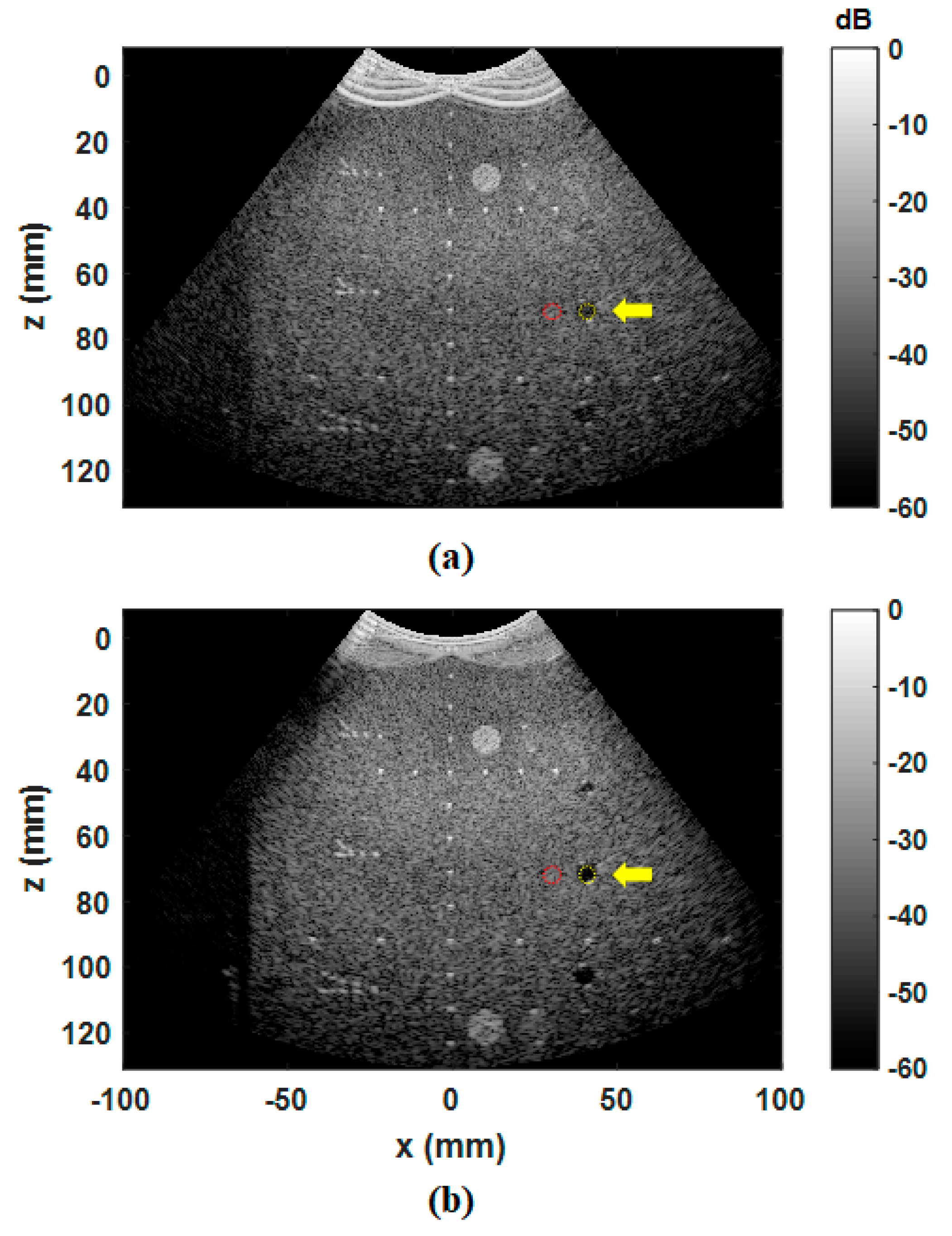
Figure 7 represents the B-mode images of the tissue mimicking phantom by using nine or 65 plane-waves. As shown in Figure 7, the image based on 65 plane-waves has clearer cyst regions (i.e., yellow dotted circle) than the image based on nine plane-waves. Quantitatively, the measured CRs are −11.3 dB and −22.5 dB for the 9-plane-wave image and the 65-plane-wave image, respectively. Additionally, the CNRs of the 9-plane-wave image and the 65-plane-wave image are 1.9 and 2.7, respectively. These results show the 65-plane-wave image has much higher contrast resolution.
Moreover, Figure 8a shows the result of B-mode image for the in vivo liver data acquired using only nine plane-waves, which suffers from very low contrast resolution. On the other hand, Figure 8b, which shows an image acquired using 65 plane-waves, can provide a clear depiction of a hepatic vessel (yellow arrows) due to increased contrast.

4. Conclusions

In this paper, an efficient transmit delay calculation method based on the reuse of time delay values of a 0° steering angle for a convex array probe in ultrasound coherent plane-wave compound imaging is presented. From the simulation study, the proposed method showed a substantial decrease in computational complexity while not affecting the image quality in plane-wave compounding imaging for a convex array transducer. As a consequence, better image quality can be achieved without additional computations for transmit delay calculations.

Author Contributions

Conceptualization, D.G. and J.K.; investigation, D.G., J.K., and I.S.; writing-original draft preparation, D.G. and J.K.; writing-review and editing, J.K. and Y.Y.; project administration, Y.Y.; funding acquisition, Y.Y.

Funding

This work was supported by the National Research Foundation of Korea (NRF) grant funded by the Korea government (MSIT) (2017R1A2B2003283) and (2017M3A9F1028497).

Conflicts of Interest

The authors declare no conflict of interest. The funders had no role in the design of the study; in the collection, analyses, or interpretation of data; in the writing of the manuscript, or in the decision to publish the results.

References

  1. Szabo, T. Diagnostic Ultrasound Imaging: Inside Out; Elsevier Academic Press: New York, NY, USA, 2004. [Google Scholar]
  2. Hoskins, P.; Martin, K.; Thrush, A. Diagnostic Ultrasound: Physics and Equipment; Cambridge University Press: Cambridge, UK, 2010. [Google Scholar]
  3. Shattuck, D.P.; Weinshenker, M.D.; Smith, S.W.; von Ramm, O.T. Explososcan: A parallel processing technique for high speed ultrasound imaging with linear phased arrays. J. Acoust. Soc. Am. 1984, 75, 1273–1282. [Google Scholar] [CrossRef] [PubMed]
  4. Tong, L.; Ramalli, A.; Jasaityte, R.; Tortoli, P.; D’hooge, J. Multi-transmit beam forming for fast cardiac imaging—Experimental validation and in vivo application. IEEE Trans. Med. Imaging 2014, 33, 1205–1219. [Google Scholar] [CrossRef] [PubMed]
  5. Tanter, M.; Fink, M. Ultrafast imaging in biomedical ultrasound. IEEE Trans. Ultrason. Ferroelectr. Freq. Control 2014, 61, 102–119. [Google Scholar] [CrossRef] [PubMed]
  6. Bae, S.; Kim, P.; Song, T.K. Ultrasonic sector imaging using plane wave synthetic focusing with a convex array transducer. J. Acoust. Soc. Am. 2018, 144, 2627–2644. [Google Scholar] [CrossRef] [PubMed]
  7. Bae, S.; Song, T.K. Methods for grating lobe suppression in ultrasound plane wave imaging. Appl. Sci. 2018, 8, 1881. [Google Scholar] [CrossRef]
  8. Hasegawa, H.; Kanai, H. High-frame-rate echocardiography using diverging transmit beams and parallel receive beamforming. J. Med. Ultrason. 2011, 38, 129–140. [Google Scholar] [CrossRef] [PubMed]
  9. Montaldo, G.; Tanter, M.; Bercoff, J.; Benech, N.; Fink, M. Coherent plane-wave compounding for very high frame rate ultrasonography and transient elastography. IEEE Trans. Ultrason. Ferroelectr. Freq. Control 2009, 56, 489–506. [Google Scholar] [CrossRef]
  10. Tanter, M.; Bercoff, J.; Sandrin, L.; Fink, M. Ultrafast compound imaging for 2-D motion vector estimation: Application to transient elastography. IEEE Trans. Ultrason. Ferroelectr. Freq. Control 2002, 49, 1363–1374. [Google Scholar] [CrossRef]
  11. Bercoff, J.; Tanter, M.; Fink, M. Supersonic shear imaging: A new technique for soft tissue elasticity mapping. IEEE Trans. Ultrason. Ferroelectr. Freq. Control 2004, 51, 396–409. [Google Scholar] [CrossRef]
  12. Sandrin, L.; Tanter, M.; Catheline, S.; Fink, M. Shear modulus imaging using 2D transient elastography. IEEE Trans. Ultrason. Ferroelectr. Freq. Control 2002, 49, 426–435. [Google Scholar] [CrossRef]
  13. Bercoff, J.; Montaldo, G.; Loupas, T.; Savery, D.; Mézière, F.; Fink, M.; Tanter, M. Ultrafast compound Doppler imaging: Providing full blood flow characterization. IEEE Trans. Ultrason. Ferroelectr. Freq. Control 2011, 58, 134–147. [Google Scholar] [CrossRef] [PubMed]
  14. Kang, J.; Jang, W.S.; Yoo, Y. High PRF ultrafast sliding compound Doppler imaging: Fully qualitative and quantitative analysis of blood flow. Phys. Med. Biol. 2018, 63, 045004. [Google Scholar] [CrossRef] [PubMed]
  15. Demené, C.; Deffieux, T.; Pernot, M.; Osmanski, B.F.; Biran, V.; Gennisson, J.L.; Sieu, L.A.; Bergel, A.; Franqui, S.; Correas, J.M.; et al. Spatiotemporal clutter filtering of ultrafast ultrasound data highly increases Doppler and fUltrasound sensitivity. IEEE Trans. Med. Imaging 2015, 34, 2271–2285. [Google Scholar] [CrossRef] [PubMed]
  16. Song, P.; Manduca, A.; Trzasko, J.D.; Chen, S. Ultrasound small vessel imaging with block-wise adaptive local clutter filtering. IEEE Trans. Med. Imaging 2017, 36, 251–262. [Google Scholar] [CrossRef] [PubMed]
  17. Couture, O.; Fink, M.; Tanter, M. Ultrasound contrast plane wave imaging. IEEE Trans. Ultrason. Ferroelectr. Freq. Control 2012, 59, 2676–2683. [Google Scholar] [CrossRef] [PubMed]
  18. Couture, O.; Bannouf, S.; Montaldo, M.; Aubry, J.F.; Fink, M.; Tanter, M. Ultrafast imaging of ultrasound contrast agents. Ultrasound Med. Biol. 2009, 35, 1908–1916. [Google Scholar] [CrossRef] [PubMed]
  19. Errico, C.; Pierre, J.; Pezet, S.; Desailly, Y.; Lenkei, Z.; Couture, O.; Tanter, M. Ultrafast ultrasound localization microscopy for deep super-resolution vascular imaging. Nature 2015, 527, 499–502. [Google Scholar] [CrossRef]
  20. Bae, S.; Kim, P.; Kang, J.; Song, T.K. An optimized plane wave synthetic focusing imaging for high-resolution convex array imaging. In Proceedings of the IEEE International Ultrasonics Symposium (IUS), Taipei, Taiwan, 21–24 October 2015. [Google Scholar]
  21. Yiu, B.Y.S.; Tsang, I.K.H.; Yu, A.C.H. GPU-based beamformer: Fast realization of plane wave compounding and synthetic aperture imaging. IEEE Trans. Ultrason. Ferroelectr. Freq. Control 2011, 58, 1698–1705. [Google Scholar] [CrossRef] [Green Version]
  22. Jensen, J.A. Field: A program for simulating ultrasound systems. Med. Biol. Eng. Comput. 1996, 34 (Suppl. 1), 351–353. [Google Scholar]
  23. Bavu, E.; Gennisson, J.-L.; Couade, M.; Bercoff, J.; Mallet, V.; Fink, M.; Badel, A.; Vallet-Pichard, A.; Nalpas, B.; Tanter, M.; et al. Noninvasive in vivo liver fibrosis evaluation using supersonic shear imaging: A clinical study on 113 hepatitis c virus patients. Ultrasound. Med. Biol. 2011, 37, 1361–1373. [Google Scholar] [CrossRef]
  24. Moon, J.H.; Hwang, J.Y.; Park, J.S.; Koh, S.H.; Park, S.Y. Impact of region of interest (ROI) size on the diagnostic performance of shear wave elastography in differentiating solid breast lesions. Acta. Radiol. 2018, 59, 657–663. [Google Scholar] [CrossRef] [PubMed]
  25. Youk, J.H.; Son, E.J.; Han, K.; Gweon, H.M.; Kim, J.A. Performance of shear-wave elastography for breast masses using different region-of-interest (ROI) settings. Acta. Radiol. 2018, 59, 789–797. [Google Scholar] [CrossRef] [PubMed]
  26. Lediju, M.A.; Trahey, G.E.; Byram, B.C.; Dahl, J.J. Short-lag spatial coherence of backscattered echoes: Imaging characteristics. IEEE Trans. Ultrason. Ferroelectr. Freq. Control 2011, 58, 1377–1388. [Google Scholar] [CrossRef] [PubMed]
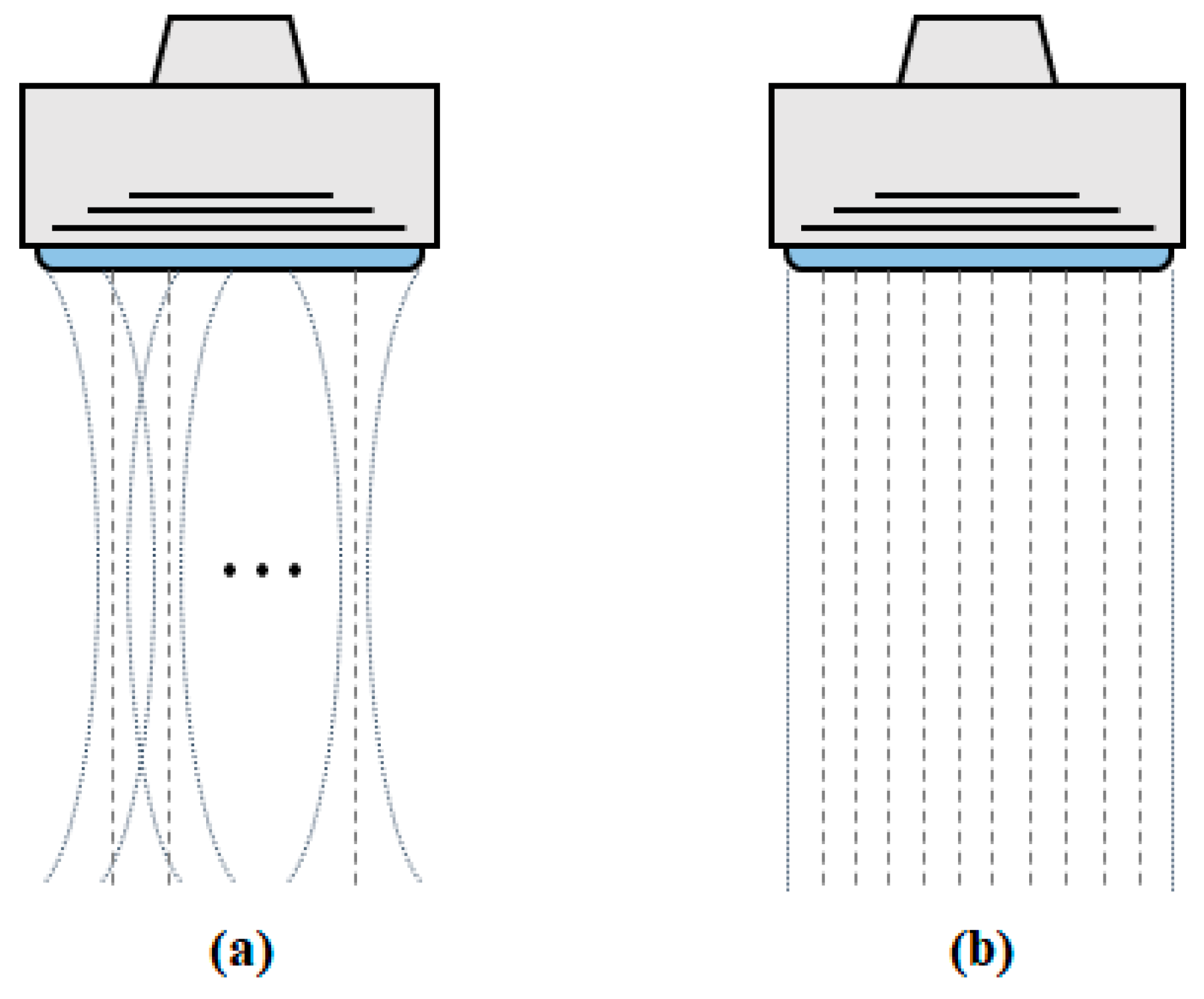
Figure 1. Beam shapes (dotted lines) and the corresponding image scanlines to be reconstructed (dashed lines) in (a) conventional focused ultrasound imaging and (b) plane-wave imaging techniques.
Applsci 09 02752 g001
Figure 2. Synthetic focusing based on the plane-wave compounding method with three plane-wave angles.
Applsci 09 02752 g002
Figure 3. Simulated B-mode images reconstructed using (a) 128 focused beams (focal depth of 25 mm) and (b) 16 plane beams (steering angles of ± 9 ° ) with L7-4 linear array (a 128-element transducer with a pitch of 298 μm and a center frequency of 5.2 MHz). The simulation was conducted using a Field II ultrasound simulator [22].
Applsci 09 02752 g003
Figure 4. Geometrical model of delay calculation for plane-wave transmission in a curved array transducer, where R is the radius of the transducer, θ P W is the steering angle of the plane-wave, and θ e l e , n is the angle between the direction vector of the nth element and the z-axis.
Applsci 09 02752 g004
Figure 5. Simulated B-mode images of point targets acquired using (a) 9 plane-waves and (b) 65 plane-waves with θ P W = ± 37.7 ° . The simulation was conducted by a Field II ultrasound simulation program [22] with a C5-2 curved array transducer (a 128-element transducer with a pitch of 425 μm, a center frequency of 3.1 MHz, and a convex angle of 75.54 degree).
Applsci 09 02752 g005
Figure 6. Delay values for various steering angles (i.e., k m i n · d θ to k m a x · d θ ) acquired from delay values for a steering angle of 0 degree.
Applsci 09 02752 g006
Figure 7. B-mode images of a tissue-mimicking phantom acquired using (a) nine plane-waves and (b) 65 plane-waves. The yellow dotted and red circles in each image indicates the cyst and background regions, respectively, which are used for calculating the contrast ratio (CR) and contrast-to-noise ratio (CNR).
Applsci 09 02752 g007
Figure 8. B-mode results of the in vivo human liver acquired using (a) nine plane-waves and (b) 65 plane-waves. The yellow arrows indicate a hepatic vessel.
Applsci 09 02752 g008
Table 1. Total number of computations of Equation (1) for the conventional method and proposed method.
VariablesConventionalProposed
N e l e N P W k m Number of computationsNumber of computations
64932576128
64576192
65324160128
644160192
1289641152256
1281152384
65648320256
1288320384
1929961728384
1921728576
659612,480384
19212,480576
Table 2. Total computation times of Equation (1) for the conventional method and proposed method.
VariablesConventionalProposed
N e l e N P W k m Computation Time (μs)Computation Time (μs)
12896419.6 ± 0.78.4 ± 0.7
12819.4 ± 0.78.9 ± 0.8
656478.6 ± 0.58.4 ± 0.7
12878.8 ± 0.88.4 ± 0.2
19299632.6 ± 0.68.5 ± 0.2
19232.8 ± 0.79.1 ± 0.2
6596148.2 ± 2.48.8 ± 0.8
192149.0 ± 0.79.3 ± 0.4