Effective Assessment of Inelastic Torsional Deformation of Plan-Asymmetric Shear Wall Systems


Abstract
:1. Introduction
2. Current Code Provisions on Torsional Design of Plan-Asymmetric Structures
3. Inelastic Torsional Response of Plan-Asymmetric Structures
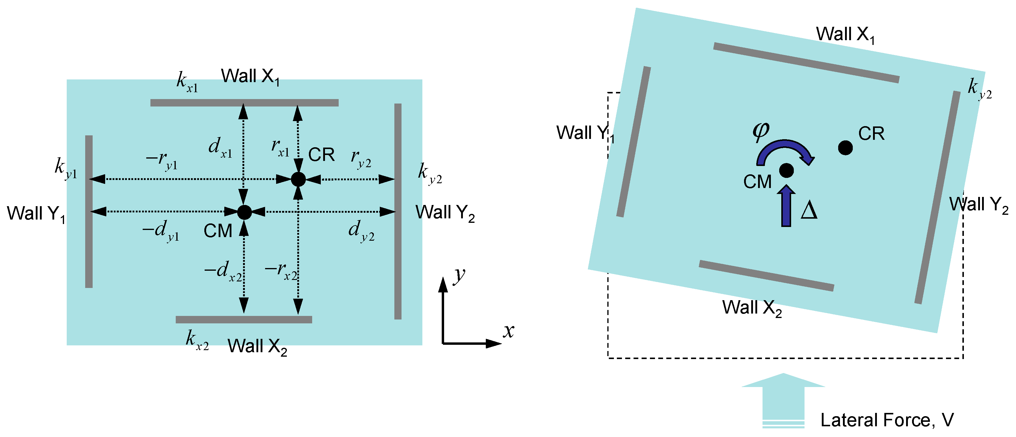
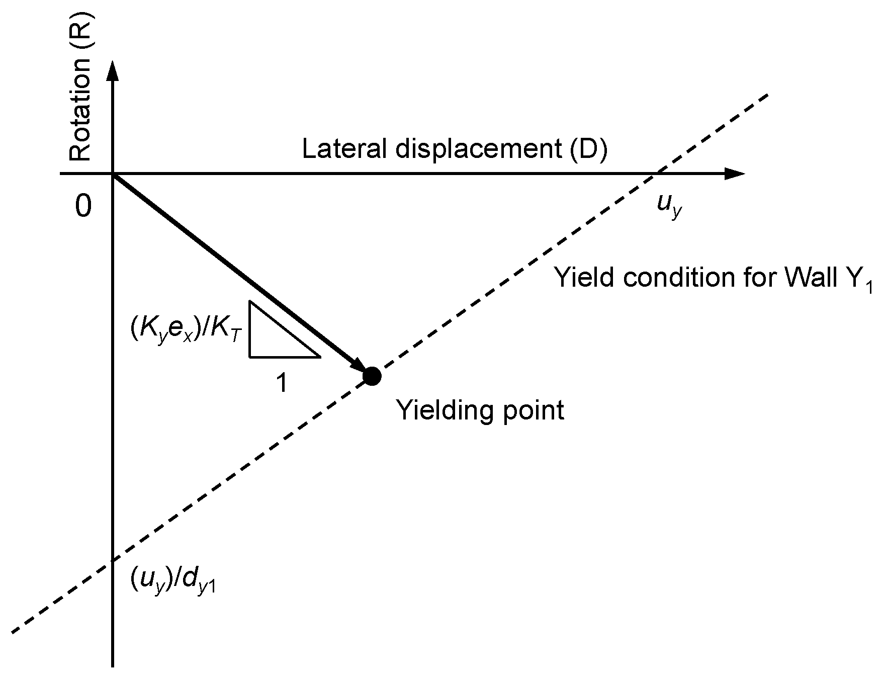
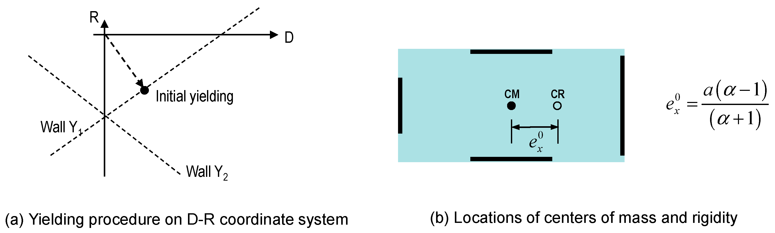
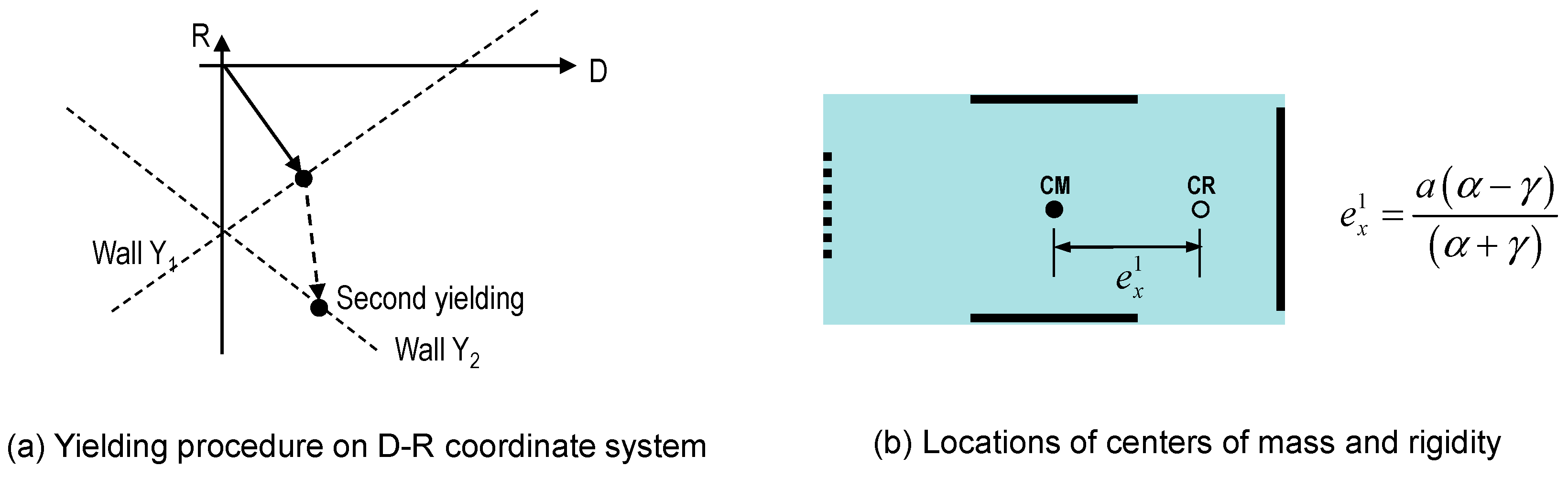
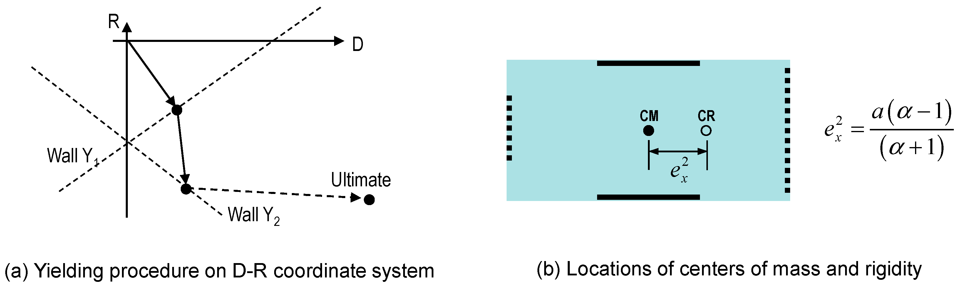
3.1. Torsional Response of Asymmetric Structures in the D-R Coordinate System
3.2. Inelastic Torsional Response Assessment Procedure
3.3. Effect of Transverse Wall Stiffness on Yielding Procedure
4. Comparison between Predictions by the Proposed Method and Time History Analysis Results
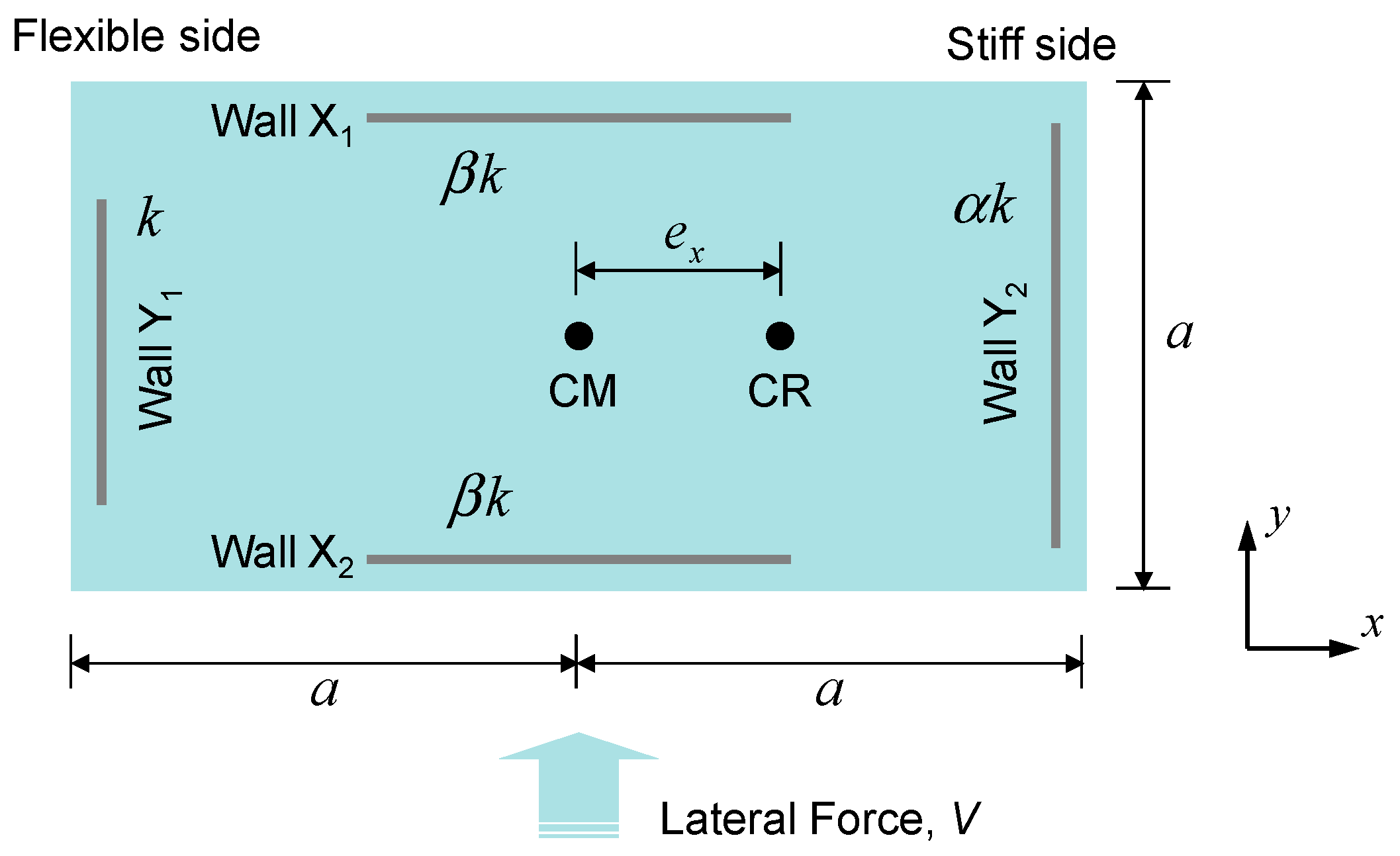
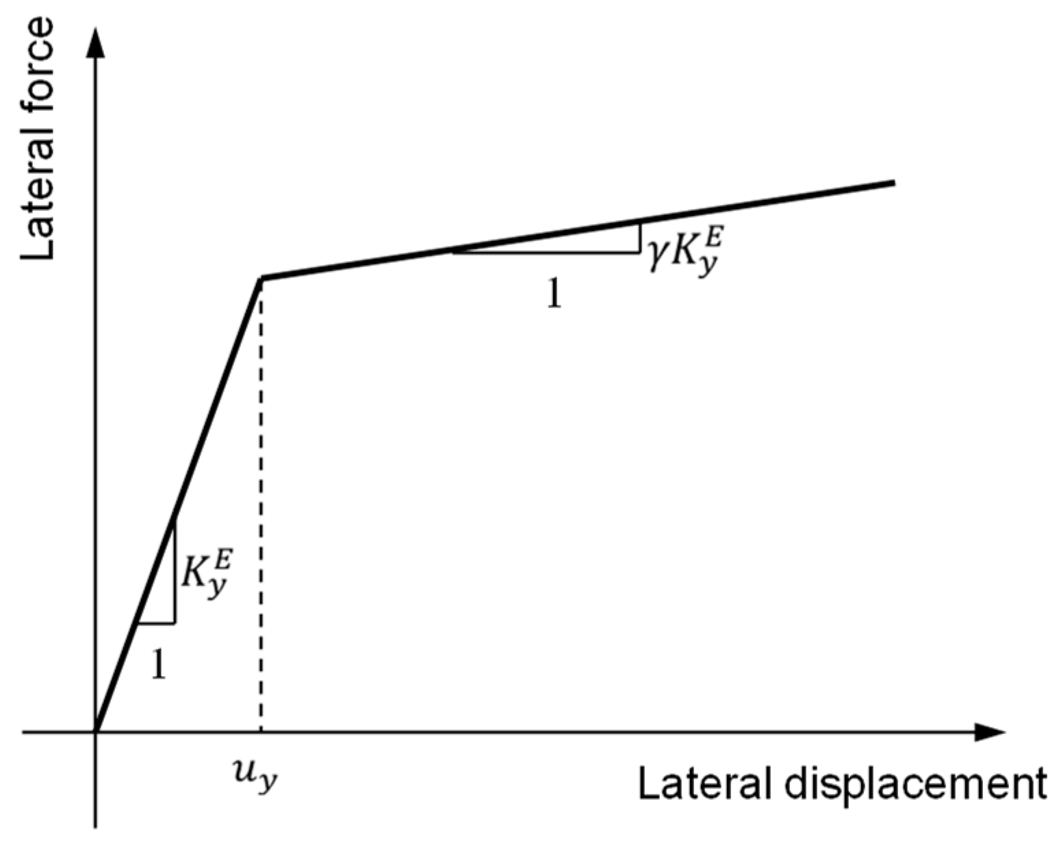
4.1. Model Problem and Analysis Method
4.2. Analysis Parameters
4.3. Analysis Results and Interpretation
5. Conclusions
- Most of the current seismic design codes such as IBC, NZS, NBCC and Eurocode are based on the force-based design approach and introduce the concept of the design eccentricity consisting of static and accidental eccentricities. They do not properly consider the inelastic deformation and actual failure mechanism of plan-asymmetric structures. As a result, they may require excessive strength and stiffness for lateral force resisting components.
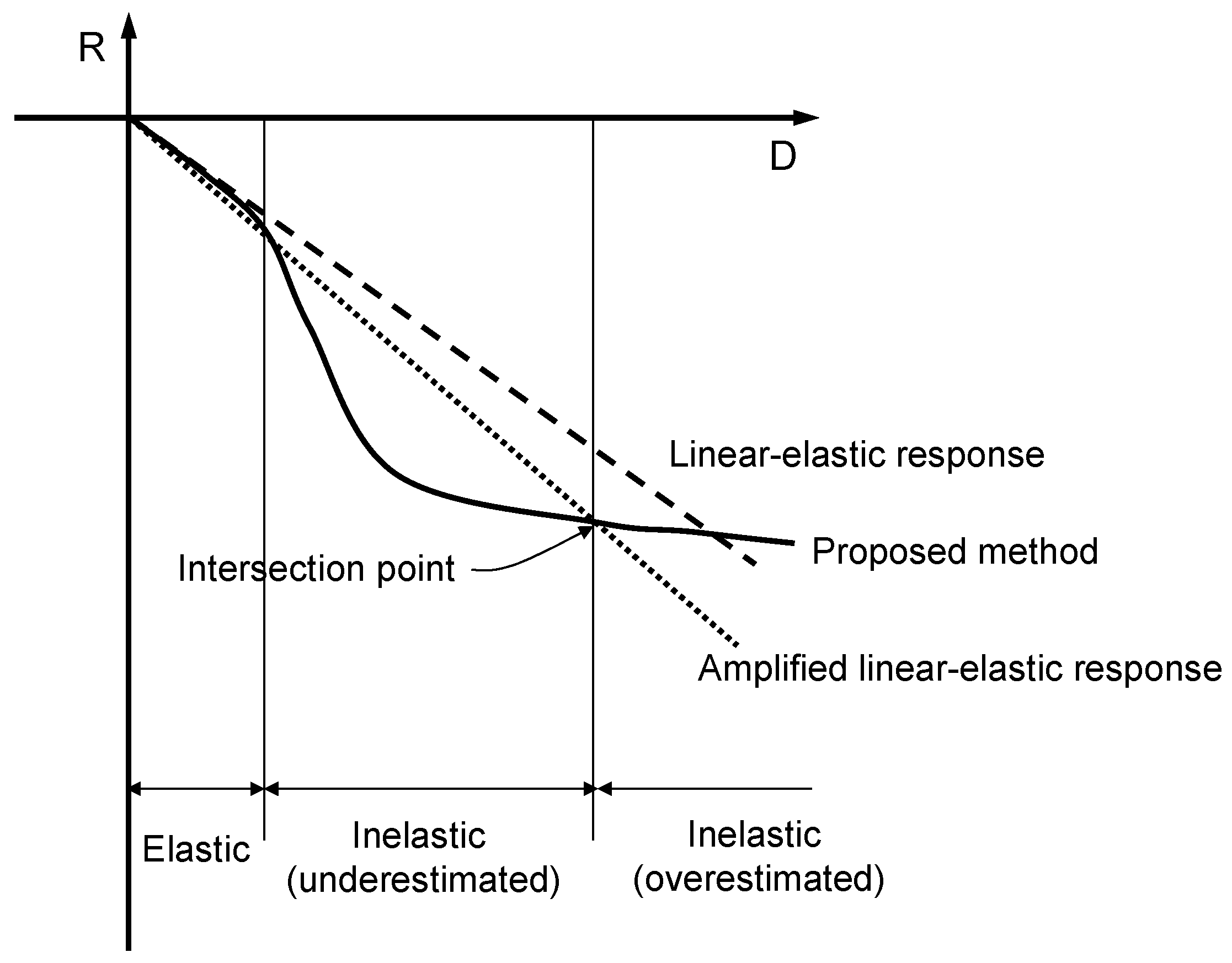
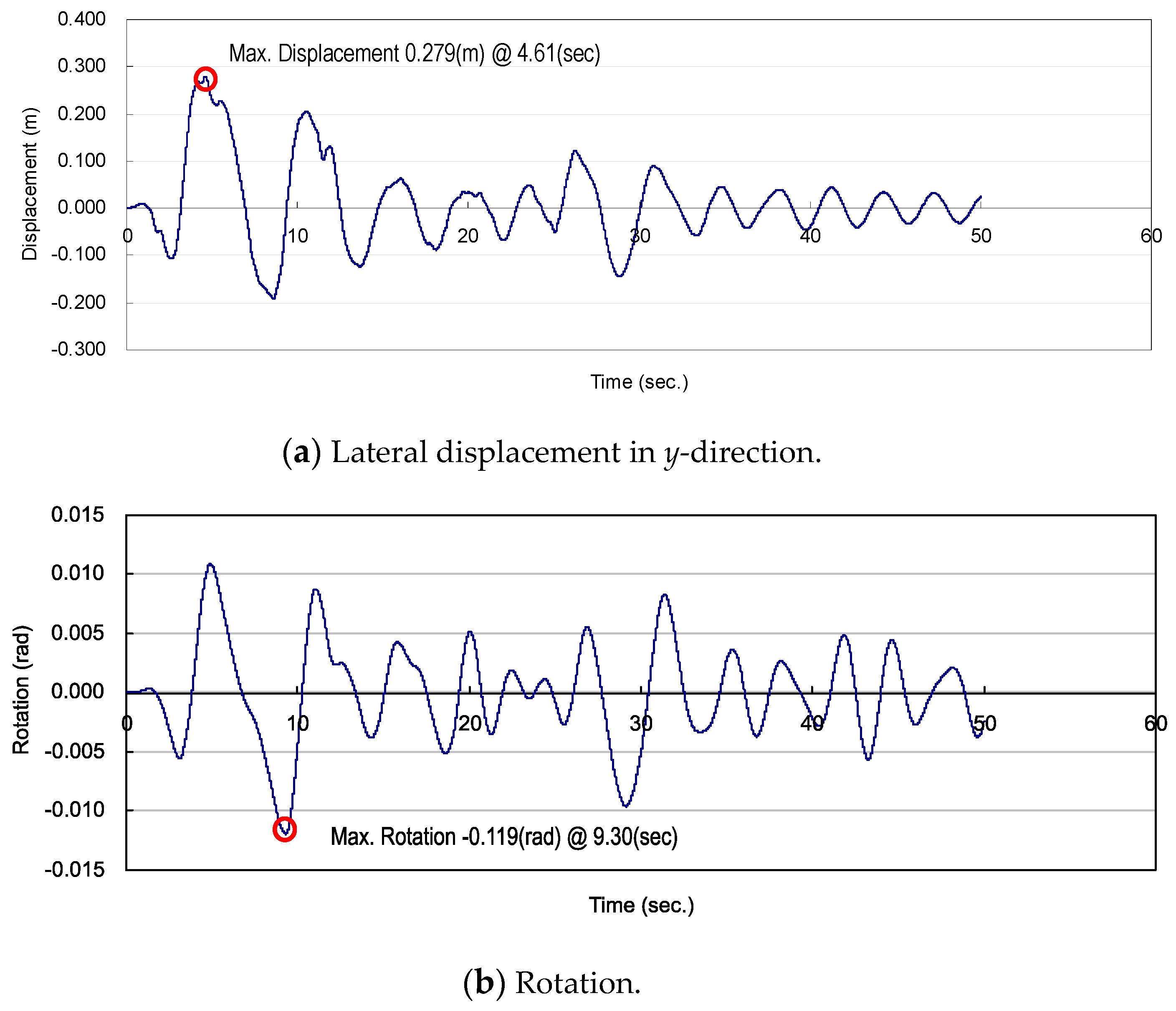
- The inelastic torsional response assessment procedure proposed in this paper shows that the linear elastic approach may both underestimate the torsional rotation at the initial yielding stage and overestimate it at the post yielding stage, resulting in inaccurate estimation of the torsional response over the entire inelastic range.
- The stiffness of the transverse wall may affect the overall yielding procedure of asymmetric structures. As a result, first yielding may occur even in the stiff side wall if the transverse wall stiffness and yield displacement are determined mainly by its length. This effect is not considered by any of the current code provisions such as IBC and Eurocode, while the procedure proposed in this study can handle it properly.
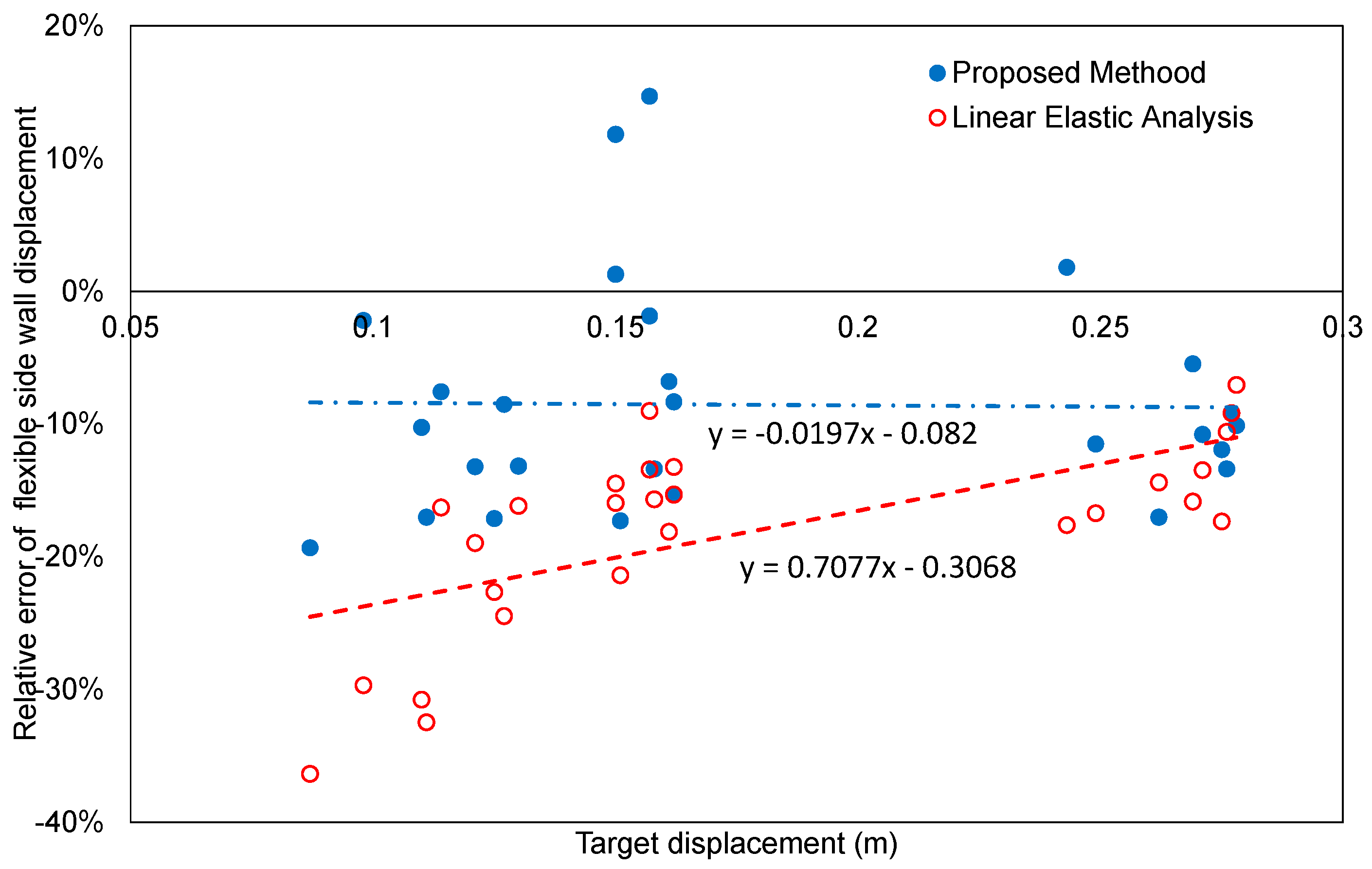
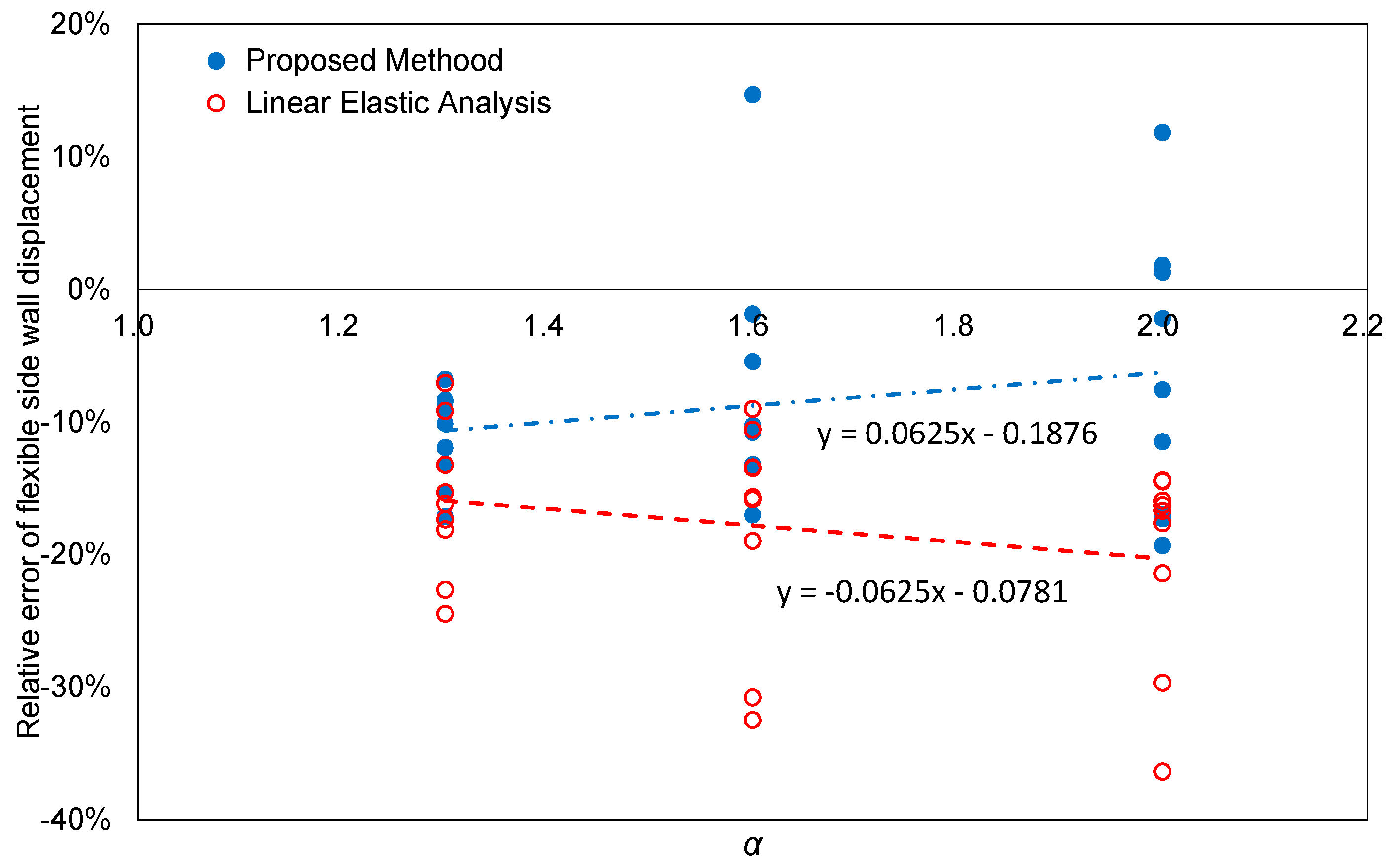
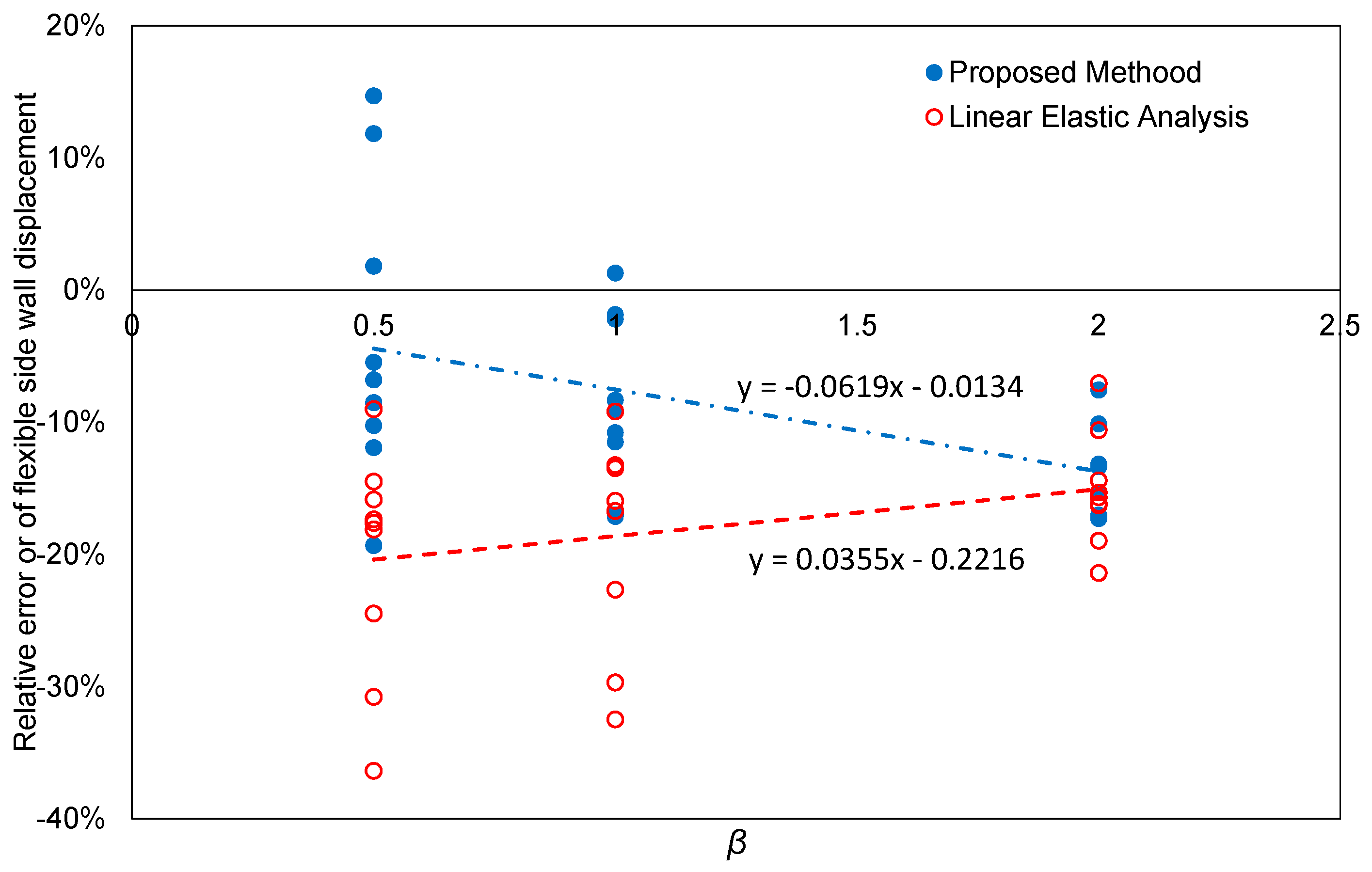
- A comparison between the results of the time history analysis and the predictions of the proposed method for the model problem under three different seismic excitations (El Centro, Kobe and Northridge) shows that the relative error averages of the proposed method range approximately from 10.0% to 13.7% and are considerably smaller than those of the linear elastic response. It also indicates that the proposed method is able to provide more accurate solutions if the level of plan-asymmetry is higher.
- In general, the proposed method underestimates the flexible side wall displacement as it is based on simple static analytical procedure and has some limitations in accurately capturing the effect of complex dynamic behavior. Therefore, some safety margin needs to be introduced, if it is applied to the design of an actual plan-asymmetric structure.
Author Contributions
Funding
Acknowledgments
Conflicts of Interest
References
- Mitchell, D.; Adams, J.; Devall, R.H.; Lo, R.C.; Weichert, D. Lessons from the 1985 Mexican Earthquake. Can. J. Civ. Eng. 1986, 13, 535–557. [Google Scholar] [CrossRef]
- Wood, S.L.; Stark, R.; Greer, S.A. Collapse of Eight-Story RC Building during 1985 Chile Earthquake. ASCE J. Struct. Eng. 1991, 117, 600–619. [Google Scholar] [CrossRef]
- Mitchell, D.; Tinawi, R.; Redwood, R.G. Damage to Buildings Due to the 1989 Loma-Prieta Earthquake—A Canadian Code Perspective. Can. J. Civ. Eng. 1990, 17, 813–834. [Google Scholar] [CrossRef]
- Mitchell, D.; DeVall, R.H.; Kobayashi, K.; Tinawi, R.; Tso, W.K. Damage to concrete structures due to the January 17, 1995, Hyogo-ken Nanbu (Kobe) earthquake. Can. J. Civ. Eng. 1996, 23, 757–770. [Google Scholar] [CrossRef]
- International Code Council. 2015 International Building Code; International Code Council: Country Club Hills, IL, USA, 2014. [Google Scholar]
- Standards New Zealand. Structural Design Actions. Part 5, Earthquake Actions: New Zealand; NZS 1170; Standards New Zealand: Wellington, New Zealand, 2004. [Google Scholar]
- National Research Council Canada and Canadian Commission on Building and Fire Codes. National Building Code of Canada, 2015; Canadian Commission on Building and Fire Codes, National Research Council of Canada: Ottawa, ON, Canada, 2015. [Google Scholar]
- British Standards Institution and European Committee for Standardization. Eurocode 8, Design of Structures for Earthquake Resistance Part 1, General Rules, Seismic Actions and Rules for Buildings; British Standards Institution: London, UK, 2004. [Google Scholar]
- Goel, R.K.; Chopra, A.K. Dual-Level Approach for Seismic Design of Asymmetric-Plan Buildings. ASCE J. Struct. Eng. 1994, 120, 161–179. [Google Scholar] [CrossRef]
- Duan, X.N.; Chandler, A.M. An optimized procedure for seismic design of torsionally unbalanced structures. Earthq. Eng. Struct. Dyn. 1997, 26, 737–757. [Google Scholar] [CrossRef]
- Humar, J.L.; Kumar, P. Effect of orthogonal inplane structural elements on inelastic torsional response. Earthq. Eng. Struct. Dyn. 1999, 28, 1071–1097. [Google Scholar] [CrossRef]
- Paulay, T. Displacement-based design approach to earthquake-induced torsion in ductile buildings. Eng. Struct. 1997, 19, 699–707. [Google Scholar] [CrossRef]
- Paulay, T. Torsional mechanisms in ductile building systems. Earthq. Eng. Struct. Dyn. 1998, 27, 1101–1121. [Google Scholar] [CrossRef]
- De Stefano, M.; Faella, G.; Ramasco, R. Inelastic seismic response of one-way plan-asymmetric systems under bi-directional ground motions. Earthq. Eng. Struct. Dyn. 1998, 27, 363–376. [Google Scholar] [CrossRef]
- De la Llera, J.C.; Chopra, A.K. Inelastic behavior of asymmetric multistory buildings. ASCE J. Struct. Eng. 1996, 122, 597–606. [Google Scholar] [CrossRef]
- Lin, J.L.; Tsai, K.C. Simplified seismic analysis of asymmetric building systems. Earthq. Eng. Struct. Dyn. 2007, 36, 459–479. [Google Scholar] [CrossRef]
- Panagiotou, M.; Restrepo, J.I.; Schoettler, M.; Kim, G. Nonlinear cyclic truss model for reinforced concrete walls. ACI Struct. J. 2012, 109, 205–214. [Google Scholar]
- Lu, Y.; Panagiotou, M. Three-dimensional cyclic beam-truss model for nonplanar reinforced concrete walls. ASCE J. Struct. Eng. 2014, 140, 04013071. [Google Scholar] [CrossRef]
- Cho, B.H.; Hong, S.G.; Ha, T.H.; Kim, D.J. Seismic evaluation of asymmetric wall systems using a modified three-dimensional capacity spectrum method. J. Vibroengineering 2015, 17, 4366–4376. [Google Scholar]
- Bento, R.; Bhatt, C.; Pinho, R. Using nonlinear static procedures for seismic assessment of the 3D irregular SPEAR building. Earthq. Struct. 2010, 1, 177–195. [Google Scholar] [CrossRef]
- Kreslin, M.; Fajfar, P. Seismic evaluation of an existing complex RC building. Bull. Earthq. Eng. 2010, 8, 363–385. [Google Scholar] [CrossRef]
- Ferraioli, M. Case study of seismic performance assessment of irregular RC buildings: Hospital structure of Avezzano (L’Aquila, Italy). Earthq. Eng. Eng. Vib. 2015, 14, 141–156. [Google Scholar] [CrossRef]
- Anagnostopoulos, S.A.; Kyrkos, M.T.; Stathopoulos, K.G. Earthquake induced torsion in buildings: Critical review and state of the art. Earthq. Struct. 2015, 8, 305–377. [Google Scholar] [CrossRef]
- Wallace, J.W. A Methodology for Seismic Design of RC Shear Walls. ASCE J. Struct. Eng. 1994, 120, 863–884. [Google Scholar] [CrossRef]
- Paulay, T. An estimation of displacement limits for ductile systems. Earthq. Eng. Struct. Dyn. 2002, 31, 583–599. [Google Scholar] [CrossRef]
- MATLAB 2014a; The MathWorks, Inc.: Natick, MA, USA, 2014.
- Mazzoni, S.; McKenna, F.; Scott, M.H.; Fenves, G.L. Open System for Earthquake Engineering Simulation: User Command, Language Manual; PEER Center, UC: Berkeley, CA, USA, 2009. [Google Scholar]
- Priestley, M.J.N.; Grant, D.N. Viscous damping in seismic design and analysis. J. Earthq. Eng. 2005, 9, 229–255. [Google Scholar] [CrossRef]
- Kunnath, S.K.; Reinhorn, A.M.; Park, Y.J. Analytical modeling of inelastic seismic response of R/C structures. ASCE J. Struct. Eng. 1990, 116, 996–1017. [Google Scholar] [CrossRef]
- Pacific Earthquake Engineering Research Center. PEER Ground Motion Database. Available online: https://ngawest2.berkeley.edu/ (accessed on 7 January 2017).
- Kaatsız, K.; Sucuolu, H. Generalized force vectors for multi-mode pushover analysis of torsionally coupled systems. Earthq. Eng. Struct. Dyn. 2014, 43, 2015–2033. [Google Scholar] [CrossRef]
- Ferraioli, M. Multi-mode pushover procedure for deformation demand estimates of steel moment-resisting frames. Int. J. Steel Struct. 2017, 17, 653–676. [Google Scholar] [CrossRef]
- Ferraioli, M.; Lavino, A.; Mandara, A. An adaptive capacity spectrum method for estimating seismic response of steel moment-resisting frames. Ing. Sismica Int. J. Earthq. Eng. 2016, 1–2, 47–60. [Google Scholar]
- Colajanni, P.; Cacciola, P.; Potenzone, B.; Spinella, N.; Testa, G. Nonlinear and linearized combination coefficients for modal pushover analysis. Ing. Sismica Int. J. Earthq. Eng. 2017, 3–4, 93–112. [Google Scholar]


| Design Code | γ | η | Note |
|---|---|---|---|
| IBC | 1.0 | ±0.05 | A torsional amplification factor Ax is considered if the diaphragm is not rigid. |
| NZS | 1.0 | ±0.1 | - |
| NBCC | 1.0 ± 0.5 | ±0.1 | - |
| Eurocode | 1.0 | 0.05 | Dynamic effect is considered by introducing an additional eccentricity value. |
| α | β | Excitation Data |
|---|---|---|
| 1.3 | 0.5 (torsionally unrestrained) | El Centro, Kobe, Northridge, Chichi, Loma Prieta, Parkfield, Turkey |
| 1.6 | 1.0 | |
| 2.0 | 2.0 (torsionally restrained) |
| Ground Acceleration Recordings [30] | |||||
|---|---|---|---|---|---|
| Earthquake | PGA (g) | PGV (m/s) | PGD (m) | DT (s) | Duration (s) |
| El Centro (May 19 1940) | 0.215 | 0.302 | 0.239 | 0.010 | 40.00 |
| Kobe (Jan. 16 1995) | 0.212 | 0.279 | 0.076 | 0.010 | 40.96 |
| Northridge (Jan. 17 1994) | 0.344 | 0.406 | 0.150 | 0.020 | 40.00 |
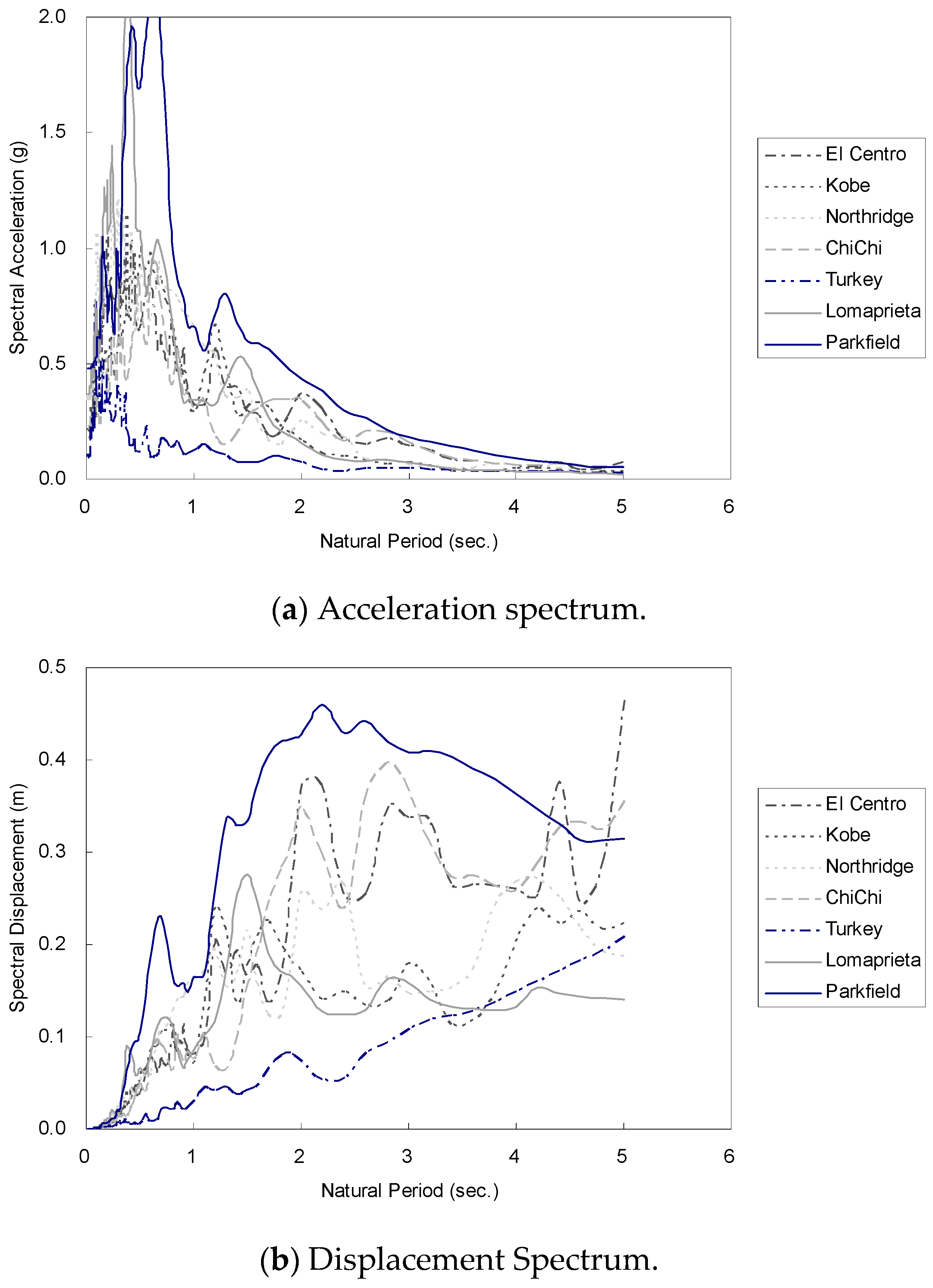
| Chi-Chi, Taiwan (Sep. 20 1999) | 0.364 | 0.554 | 0.256 | 0.004 | 150.00 |
| Kocaeli, Turkey (Aug. 17 1999) | 0.376 | 0.795 | 0.705 | 0.010 | 60.00 |
| Loma Prieta (Oct. 18 1989) | 0.367 | 0.329 | 0.072 | 0.005 | 39.95 |
| Parkfield (Jun. 28 1966) | 0.476 | 0.751 | 0.225 | 0.010 | 43.69 |
| α | β | Time History Analysis | Proposed Method | Linear Elastic Response | ||||||
|---|---|---|---|---|---|---|---|---|---|---|
| Δcen_TH (m) | ϕcen_TH (rad) | Δflex_TH (m) | ϕcen_pro (rad) | Δflex_pro (m) | Relative Error (%) | ϕcen_elas (rad) | Δflex_elas (m) | Relative Error (%) | ||
| 1.30 | 0.50 | 0.275 | −0.019 | 0.369 | −0.010 | 0.324 | −12.13 | −0.007 | 0.308 | −16.57 |
| 1.00 | 0.277 | −0.012 | 0.338 | −0.006 | 0.307 | −9.17 | −0.006 | 0.307 | −9.14 | |
| 2.00 | 0.278 | −0.010 | 0.326 | −0.003 | 0.295 | −9.56 | −0.005 | 0.304 | −6.88 | |
| 1.60 | 0.50 | 0.269 | −0.023 | 0.385 | −0.019 | 0.363 | −5.72 | −0.012 | 0.329 | −14.67 |
| 1.00 | 0.271 | −0.020 | 0.371 | −0.012 | 0.329 | −11.24 | −0.011 | 0.326 | −12.16 | |
| 2.00 | 0.276 | −0.017 | 0.359 | −0.007 | 0.309 | −13.85 | −0.010 | 0.324 | −9.79 | |
| 2.00 | 0.50 | 0.243 | −0.028 | 0.386 | −0.029 | 0.388 | 0.45 | −0.017 | 0.326 | −15.46 |
| 1.00 | 0.249 | −0.027 | 0.383 | −0.018 | 0.341 | −10.87 | −0.016 | 0.328 | −14.46 | |
| 2.00 | 0.262 | −0.024 | 0.382 | −0.011 | 0.316 | −17.26 | −0.014 | 0.333 | −12.71 | |
| Average of absolute relative errors | - | 10.03 | - | 12.43 | ||||||
| α | β | Time History Analysis | Proposed Method | Linear Elastic Response | ||||||
|---|---|---|---|---|---|---|---|---|---|---|
| Δcen_TH (m) | ϕcen_TH (rad) | Δflex_TH (m) | ϕcen_pro (rad) | Δflex_pro (m) | Relative Error (%) | ϕcen_elas (rad) | Δflex_elas (m) | Relative Error (%) | ||
| 1.30 | 0.50 | 0.127 | −0.012 | 0.188 | −0.008 | 0.169 | −9.94 | −0.003 | 0.142 | −24.38 |
| 1.00 | 0.125 | −0.011 | 0.181 | −0.005 | 0.151 | −16.74 | −0.003 | 0.139 | −23.43 | |
| 2.00 | 0.130 | −0.007 | 0.167 | −0.003 | 0.144 | −13.48 | −0.002 | 0.142 | −14.99 | |
| 1.60 | 0.50 | 0.110 | −0.017 | 0.195 | −0.013 | 0.175 | −10.39 | −0.005 | 0.134 | −31.11 |
| 1.00 | 0.111 | −0.016 | 0.194 | −0.010 | 0.160 | −17.31 | −0.004 | 0.133 | −31.19 | |
| 2.00 | 0.121 | −0.011 | 0.174 | −0.006 | 0.149 | −14.12 | −0.004 | 0.142 | −18.41 | |
| 2.00 | 0.50 | 0.087 | −0.018 | 0.176 | −0.011 | 0.142 | −19.57 | −0.006 | 0.117 | −33.62 |
| 1.00 | 0.098 | −0.017 | 0.182 | −0.011 | 0.155 | −14.58 | −0.006 | 0.129 | −29.15 | |
| 2.00 | 0.114 | −0.012 | 0.172 | −0.009 | 0.160 | −6.75 | −0.006 | 0.145 | −15.64 | |
| Average of absolute relative errors | - | 13.65 | - | 24.66 | ||||||
| α | β | Time History Analysis | Proposed Method | Linear Elastic Analysis | ||||||
|---|---|---|---|---|---|---|---|---|---|---|
| Δcen_TH (m) | ϕcen_TH (rad) | Δflex_TH (m) | ϕcen_pro (rad) | Δflex_pro (m) | Relative Error (%) | ϕcen_elas (rad) | Δflex_elas (m) | Relative Error (%) | ||
| 1.30 | 0.50 | 0.161 | −0.012 | 0.221 | −0.009 | 0.205 | −7.28 | −0.004 | 0.180 | −18.45 |
| 1.00 | 0.162 | −0.008 | 0.204 | −0.005 | 0.189 | −7.48 | −0.004 | 0.180 | −11.96 | |
| 2.00 | 0.162 | −0.009 | 0.209 | −0.003 | 0.177 | −15.31 | −0.003 | 0.177 | −15.36 | |
| 1.60 | 0.50 | 0.157 | −0.011 | 0.211 | −0.017 | 0.241 | 14.13 | −0.007 | 0.192 | −9.13 |
| 1.00 | 0.157 | −0.012 | 0.216 | −0.010 | 0.209 | −3.25 | −0.006 | 0.189 | −12.59 | |
| 2.00 | 0.158 | −0.012 | 0.217 | −0.006 | 0.188 | −13.56 | −0.005 | 0.185 | −14.57 | |
| 2.00 | 0.50 | 0.150 | −0.016 | 0.228 | −0.021 | 0.257 | 12.93 | −0.010 | 0.201 | −11.65 |
| 1.00 | 0.150 | −0.016 | 0.232 | −0.017 | 0.233 | 0.59 | −0.009 | 0.197 | −14.93 | |
| 2.00 | 0.151 | −0.018 | 0.243 | −0.010 | 0.199 | −17.98 | −0.008 | 0.192 | −20.91 | |
| Average of absolute relative errors | - | 10.28 | - | 14.39 | ||||||
© 2019 by the authors. Licensee MDPI, Basel, Switzerland. This article is an open access article distributed under the terms and conditions of the Creative Commons Attribution (CC BY) license (http://creativecommons.org/licenses/by/4.0/).
Share and Cite
Ha, T.; Hong, S.-G.; Cho, B.-H.; Kim, D.-J. Effective Assessment of Inelastic Torsional Deformation of Plan-Asymmetric Shear Wall Systems. Appl. Sci. 2019, 9, 2814. https://doi.org/10.3390/app9142814
Ha T, Hong S-G, Cho B-H, Kim D-J. Effective Assessment of Inelastic Torsional Deformation of Plan-Asymmetric Shear Wall Systems. Applied Sciences. 2019; 9(14):2814. https://doi.org/10.3390/app9142814
Chicago/Turabian StyleHa, Taehyu, Sung-Gul Hong, Bong-Ho Cho, and Dae-Jin Kim. 2019. "Effective Assessment of Inelastic Torsional Deformation of Plan-Asymmetric Shear Wall Systems" Applied Sciences 9, no. 14: 2814. https://doi.org/10.3390/app9142814
APA StyleHa, T., Hong, S.-G., Cho, B.-H., & Kim, D.-J. (2019). Effective Assessment of Inelastic Torsional Deformation of Plan-Asymmetric Shear Wall Systems. Applied Sciences, 9(14), 2814. https://doi.org/10.3390/app9142814