Abstract
Optical tweezers are widely used for noninvasive and precise micromanipulation of living cells to understand biological processes. By focusing laser beams on cells, direct cell manipulation with optical tweezers can achieve high precision and flexibility. However, direct exposure to the laser beam can lead to negative effects on the cells. These phenomena are also known as photobleaching and photodamage. In this study, we proposed a new indirect cell micromanipulation approach combined with a robot-aided holographic optical tweezer system and 3D nano-printed microtool. The microtool was designed with a V-shaped head and an optical handle part. The V-shaped head can push and trap different sizes of cells as the microtool moves forward by optical trapping of the handle part. In this way, cell exposure to the laser beam can be effectively reduced. The microtool was fabricated with a laser direct writing system by two-photon photopolymerization. A control strategy combined with an imaging processing algorithm was introduced for automated manipulation of the microtool and cells. Experiments were performed to verify the effectiveness of our approach. First, automated microtool transportation and rotation were demonstrated with high precision. Second, indirect optical transportations of cells, with and without an obstacle, were performed to demonstrate the effectiveness of the proposed approach. Third, experiments of fluorescent cell manipulation were performed to confirm that, indicated by the photobleaching effect, indirect manipulation with the microtool could induce less laser exposure compared with direct optical manipulation. The proposed method could be useful in complex biomedical applications where precise cell manipulation and less laser exposure are required.
1. Introduction
The invention of optical tweezers has allowed scientists to develop an unprecedented manipulative ability at the single-cell level [1,2,3]. Focused laser beams, which can trap biological cells, cell organelles, and DNA bundles in a confined space [4,5,6], are opening up unexplored research areas that focus on single cells. In many biological and biomedical experiments, such as cell-to-cell interaction [7], cell sorting [8], and cell mechanical stiffness characterization [9], single-cell analysis has become feasible due to the customization of optical traps via light field waveform modulators [10,11]. Cell transportation has attracted increased attention due to the fact that cell positioning is usually a basic and vital technique that is required in single-cell analysis [12,13,14,15,16,17,18,19].
Techniques for cell transportation with optical tweezers can be classified into two, namely, direct and indirect manipulation. Direct optical manipulation techniques induce a trapping force by directly focusing the laser on the cell [20,21,22], in which laser beams act as special end-effectors. Using the direct technique, a large number of cells can be manipulated individually or simultaneously in a series or parallel manner with high precision and high efficiency [23,24]. However, direct manipulation by the high focused laser beams may cause photobleaching and photodamage to the cells. The photobleaching makes it difficult to precisely visualize the spatio-temporal distribution of interesting proteins in the cells by combining fluorescent probes and optical tweezers. The photodamage may result in an impaired functionality or even the death of the cells [25,26,27,28]. To address these problems, indirect optical manipulation approaches are proposed.
Indirect techniques employ intermediate micro-objects as end-effectors of optical tweezers to manipulate cells. Instead of focusing on the cells, laser beams are focused on the non-biological and biocompatible micro-objects, thereby driving the micro-objects to interact with the biological cells [29,30]. Cell manipulation is achieved under the reaction force of the micro-objects. Microbeads are ideal examples for optical trapping due to their spherical shape and manufacturing uniformity. Arai et al. used two microbeads to push a yeast cell [31]; Koss et al. proposed an optical gripper with an ensemble of optically trapped beads to reduce the laser exposure of gripped cells [32]. Although the use of microbeads for indirect manipulation in combination with automated control strategies is well-established [33,34,35], their transport with microbeads is frequently unstable, and laser fields remain close to trapped cells.
With the advancement of the direct laser writing technique, designable microscale mechanisms with 3D nano features were printed using the two-photon photopolymerization (2PP) method and trapped as microtools for indirect optical manipulation [36]. Various microhands, as the end-effector of optical tweezers, were proposed, and their manipulability by optical tweezers was verified [29,37]. The optical manipulation of highly task-specific micromechanisms, such as an articulated microrobot and microsyringe, as fabricated by the 2PP method, was further investigated [38,39,40]. Aekbote et al. conducted a meaningful and innovative study to enable indirect optical cell manipulation [41]. In their study, however, meticulous functionalization of SU-8 microstructure and cells were needed to form a microstructure–cell attachment and prevent the cell from escaping from the structure during manipulation. These studies have contributed to the manipulation of the fabricated microtool. However, there are only a few examples of automated cell manipulation using microtools [42,43]. Because often more than three spherical trap points in each microtool need to be manipulated simultaneously to transport a cell, manual manipulation is often difficult and tedious in its application.
In this study, we propose a new approach for precise and safe transportation of biological cells with a robot-aided holographic optical tweezer (HOT) manipulation system. A microtool is designed and fabricated through the 2PP method with nano-scale resolution. A control strategy combined with imaging processing algorithms is developed for automated cell transportation. The surface functionalization of the microtool is saved and the cells can be stably transported with high precision using the proposed approach. Furthermore, experiments on yeast cells, which were stained with a fluorescent dye, demonstrate that indirect optical manipulation with the proposed microtool can effectively reduce the photobleaching effect. This finding implies that laser exposure on the cells is reduced. The proposed microtool is expected to be used in complex biomedical applications, where precise cell manipulation and less laser exposure are required, such as single-cell-based drug screening and cell microsurgery.
The remainder of this paper is organized as follows. Section 2 presents the design and fabrication of the proposed microtool. Section 3 introduces the indirect optical cell transportation strategy using the robot-aided HOT system. Section 4 reports the experimental results to illustrate the performance of the proposed approach and concludes.
2. Materials and Methods
2.1. Design and Fabrication of Microtool
2.1.1. Microtool Concept
Figure 1 shows a microtool that is designed to push cells. The microtool consists of two parts, namely, a V-shaped head and handle for manipulation of cells and for interaction with optical tweezers, respectively (Figure 1a). The V-shaped head has a 2 µm-wide flattened bottom and two 6 µm-length sides at 135°. The V-shaped head has a height of 6 µm. Further, the handle part is an equilateral triangle with a 4 µm microsphere at each vertex and 17 µm-length square bar at each side. The square bar has a thickness of 1 µm. Figure 1c shows detailed dimensions of the microtool. In addition, the microtool size and shape can be readily adapted to be larger or smaller depending on the target cells due to the simple fabrication process.
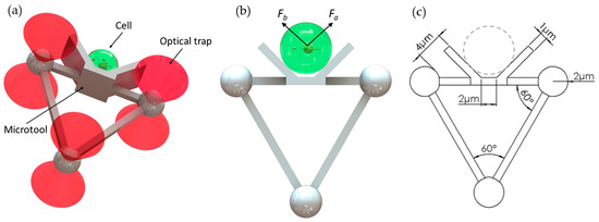
Figure 1.
Designed microtool. (a) Schematics of the proposed microtool. (b) Two push force, namely, Fa and Fb, are generated by the baffles on the left and right sides of the V-shaped head of the microtool. (c) Dimensions of the microtool.
The design has the following advantages. First, the V-shaped head is applicable to the manipulation of different sizes of cells. As the microtool moves forward, the V-shaped head will generate forces (see Fa and Fb in Figure 1b) to trap the cell at the center bottom of the V-shaped head. Therefore, the microtool allows stable manipulation without cells adhering to the microtool. The cells, regardless of their sizes, will be minimally exposed to the laser beams. Second, the microtool is optimized for optical manipulation. The pose of the microtool can be manipulated by controlling the positions of the three handling microspheres with three optical traps. The formation of three microspheres in an equilateral triangle will be of benefit to the visual servo control method due to the simplified image processing process. The diameter of each optical handling microsphere is set to 4 µm by the experiment. The diameter is much larger than the 1064 nm wavelength of the optical tweezer, and thus conventional ray-optics theory can be used to analyze the trapping actions of the optical traps on the microspheres. Moreover, to prevent the optical handling spheres from escaping the traps and achieve high-precision manipulation, a control constraint [22] could be introduced in the control strategy. During optical manipulation, the deviations of the trap center from the center of the microsphere will be smaller than 1.4 µm, which is seven-tenths of the microsphere radius. Therefore, utilizing optical traps that have the same parameters as those in our previous work [22] and considering cells with radii ranging from 2 µm to 10 µm, the minimum distance between the trap center and cell edge is twice that of the sphere radius (i.e., 4 µm, as shown in Figure 1c). The change of the laser beam as it overlaps with cells is further decreased. Hence, cell exposure to the laser beam can be effectively reduced.
2.1.2. Fabrication of Microtool
The microtools were fabricated using a commercial 3D direct laser writing setup (Nanoscribe GmbH, Germany) via 2PP. The system employs a femtosecond fiber laser with a wavelength of 780 nm and a pulse length of 100 fs. The microtool is fabricated by solidifying the photoresist through a laser directly that scans along a predetermined path. With the advantage of 2PP, this method can achieve a high resolution of 100 nm, which is beneficial for the fabrication of precision microstructures.
The material for fabricating the microtool should at least satisfy the following conditions: (1) high-precision fabrication can be achieved; (2) biocompatibility is assured; (3) the refractive index is appropriate, such that the optical trapping efficiency and stiffness of the material in cell culture medium are efficiently high; (4) the density is suitable such that the microtool is basically at the same horizontal plane with the cells and can be manipulated well by optical traps. Therefore, photoresist IP-L 780 (Nanoscribe GmbH) was selected for experimental use in our study. The procedures for the fabrication of the microtool are described as follows. First, the photoresist is prepared over a clean glass substrate by simple drop-casting. Second, the photoresist-coated substrate was mounted on the laser direct writing machine with a 63× oil immersion objective (N.A. = 1.4, Zeiss). The microtools were fabricated by laser focus point bottom-up scanning, in which layer by layer solidification is driven by galvanometric mirrors in the x–y directions and by a piezo motor in the z-direction (Figure 2a). The laser power was set to 40 mW with the printing parameters of 0.3 µm slicing distance and hatching distance. In our study, polymerizing one microtool takes approximately 5 s. Third, the polymerized substrate was finally developed in baths of propylene glycol methyl acetate and isopropyl alcohol for 2 and 5 min, respectively. Figure 2b shows a picture of the fabricated microtool, which was coated with a 5 nm-thick gold layer for enhanced image contrast and imaged under an environmental scanning electron microscope (ESEM, Quanta 250, FEI). The fabricated microtools, without any coating, were removed from the glass substrate and transferred to culture dishes with a micropipette tip before the cell experiments.
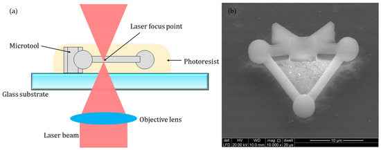
Figure 2.
Fabrication of the microtool. (a) Schematics of the 3D printing process. (b) Micrograph of the microtool coated with a 5 nm-thick gold layer under an environmental scanning electron microscope (ESEM).
2.2. Cell Transportation Strategy
2.2.1. Experimental Setup
The experiments were conducted on a robot-aided HOT cell manipulation system as previously described [22]. This system, as shown in Figure 3, contained three functional modules, namely, executive, sensory, and control. The executive module mainly consisted of a motorized stage and a HOT device (Arryx, Bioryx 200). The HOT device employed a spatial light modulator to split a single laser beam (V-I06C-3000 OEM J-series, Spectra Physics) into several separate optical traps, each of which could be controlled individually by software programming. An infrared laser source with a wavelength of 1064 nm was used. The sensory module consisted of an inverted microscope (Ti-U, Nikon Corporation, Tokyo, Japan) and a CCD camera (FO124SC, Foculus, Finning, Germany), with a resolut ion of 640 × 480 pixels and a maximum frame rate of 86 fps. Images of microtools and cells in the field of view were allowed to pass into the camera through a diachronic mirror that reflects laser light into the inverted objective (Plan Apo 60× /1.20 WI, Nikon Corporation, Tokyo, Japan). The poses of the microtool and positions of the cells in the field of view were obtained through real-time image processing. The control module, mainly composed of a motion controller and a computer, would process the visual feedback information and generate the control outputs. All components were installed on an anti-vibration table in a dustless environment. A control software with a user-friendly graphic user interface (GUI) was developed to perform the experiments using C++ language.
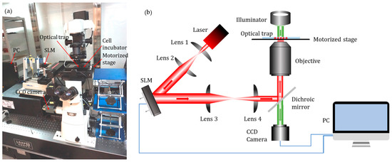
Figure 3.
Robot-aided holographic optical tweezer (HOT) cell manipulation system. (a) Experimental setup. (b) Schematic illustration.
2.2.2. Control Strategy
Figure 4 illustrates the control sequences of the indirect transportation of biological cells with our HOT system. First, an operator would determine a target cell, which has the phenotypes of interest, then set the transport requirements through the GUI. Afterward, visual servo control was performed to transport the cell by manipulating the microtool with optical traps. In our study, the microtool must move toward a consistent direction while pushing the cell, because the cells were manipulated in a non-prehensile manner. Otherwise, the cell may slip away from the microtool. Therefore, this study focuses only on translational and rotational movements of the microtool. Specifically, a translational movement is used to push the cell to move along a straight path, and a rotational movement is used to adjust the microtool’s direction when the actual direction does not coincide with the desired direction.
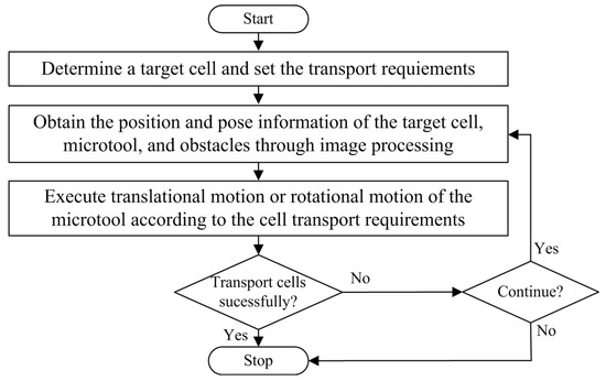
Figure 4.
Control sequences of indirect transport of biological cells with the robot-aided HOT system by manipulating the microtool.
A geometry-based calibration method was introduced to set up the mapping relationship between the world and microtool coordinate systems. Figure 5 shows the kinematic diagram of the microtool, where [Xw, Yw] denotes the world coordinate system; [XR, YR] is the microtool coordinate system, which is located at the microtool center (OR); D pertains to the central point of the rod that connects the two optical handling spheres A and B of the microtool; is the robot head direction, which is coincident with that of the XR axis θ is the rotational angle between the world and the microtool coordinate systems; and (a, b) is the coordinate value of OR in the world coordinate system. The mapping relationship between the world and microtool coordinate systems can be derived from the geometry of the microtool and expressed as follows:
where (xR, yR) is the coordinate value of a certain point in the microtool coordinate system, and (xW, yW) is its corresponding value in the world coordinate system.
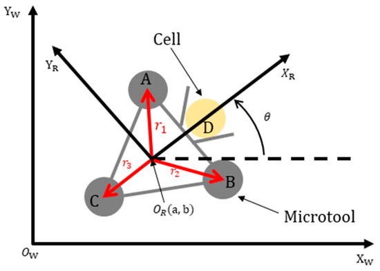
Figure 5.
Kinematic diagram of the microtool.
The kinematic diagram of the microtool shows that the microtool can act similarly to an omnidirectional microrobot [44], whose translational and rotational movements can be controlled independently and simultaneously. Specifically, the microtool pose can be controlled by manipulating the three handling spheres (see A, B, and C in Figure 5) with three optical traps. In this paper, we assumed that the movement velocities of the handling spheres were the same as those of the optical traps. This observation can be justified by experimentally setting the appropriate movement velocities of the optical traps. The effect of the inertia force of the cells is negligible due to the low Reynolds number in the liquid environments [45], such that the cells were supposed to be stably pushed with the microtool.
2.2.3. Image Processing
Cell positions were detected using a method that is similar to that presented in detail in other studies [22,43]. In this study, only the image processing algorithms for the microtool posture recognition are introduced. As a representative demonstration, Figure 6 shows the procedures of image processing to recognize the microtool from the mixture of a microtool and two cells. First, the original color image (Figure 6a) was transformed into a grayscale image and the Gaussian filter was utilized to smoothen the noise in the image (Figure 6b). Then, Otsu’s method was introduced to obtain a threshold value and separate the cells and microtool from the background. The global optimal threshold value was selected by maximizing between-class variance. After the image was binarized (Figure 6c), the Sobel operator was used to recognize the edges of the objects (Figure 6d). The three handling spheres of the microtool and two cells were subsequently located with the Hough transform (Figure 6e) [46]. Finally, the poses of the microtool, such as position and direction, can be calculated on the basis of the sizes of the identified contours and geometric position relationship of the located microspheres (Figure 6f).
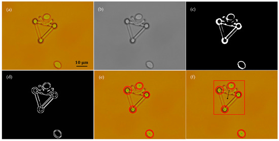
Figure 6.
Recognition of the microtool poses from a mixture of two cells and the microtool through image processing. (a) Original color image. (b) Filtered grayscale image. (c) Binary image. (d) Edges of the microtool the cells. (e) Location of three handling spheres of microtool and two cells. (f) Poses of microtool.
3. Results
Experiments were performed to verify the effectiveness of our approach. The output laser power from the laser source was set to 0.3 W for each optical trap. Each pixel in the captured images had a size of 0.12 µm. To demonstrate the robustness of our approach, we set different illumination intensities in the experiments. The sampling frequency of the visual servo control system was 15 Hz. All the experiments were performed at room temperature.
3.1. Manipulability of Microtool
Experiments were first conducted to demonstrate the manipulation performance of the fabricated microtool.
3.1.1. Movement of Microtool in Optical Traps and Fluid Flows
In the first experiment, a viscous drag force method was introduced to test the movement of the microtool in optical traps and fluid flows. Figure 7 illustrates the geometry of this experiment. First, a microtool was trapped and immobilized in the suspending medium. To avoid friction and collision between the microtool and culture dish, the microtool was lifted 1 µm from the bottom of the culture dish. At this moment, the positions of the traps, i.e., Trap1, Trap2, and Trap3 in Figure 7, coincided with those of the microtool handling spheres, i.e., A, B, and C in Figure 7, respectively. Then, the motorized stage was moved in a defined velocity and applied to the fluid flow passing the microtool. The microtool handling spheres would deviate from the traps and be immobilized in new balanced positions under the dragging force of the fluid flow and trapping force of the traps. By recording the positions of the microsphere before and after moving the motorized stage, we could obtain the deviations of the optical handling spheres from the optical traps. Figure 8 shows the deviations of A, B and C from optical trap centers as functions of fluid flow velocities when the laser power of each optical trap was set to 0.3 W. We observed that the deviations of A, B, and C are nearly identical, thereby demonstrating positive stability and balance of the microtool under optical traps and fluid flows. Furthermore, we observed that the deviations are no larger than seven-tenths of the sphere radius until the velocity of the fluid flows increases to 30 µm/s, which exhibits high trapping efficiency and stiffness. The experimental results lay the groundwork for the subsequent translational and rotational manipulation of the microtool.
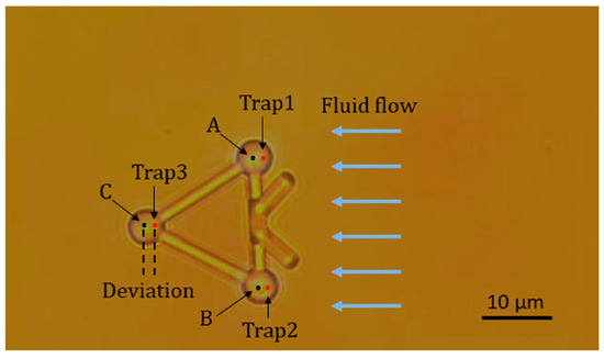
Figure 7.
Microtool in three optical traps and fluid flows.
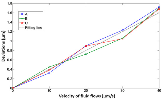
Figure 8.
Deviations of optical handling spheres, namely, A, B, and C, of the microtool as functions of fluid flow velocities when the laser power of each optical trap is 0.3 W.
3.1.2. Translation of Microtool
In the second experiment, we demonstrated the translational movement of the microtool as manipulated by optical tweezers. Three optical traps were created to trap the three handling spheres of the microtool, i.e., A, B, and C in Figure 9. The microtool was transported forward along a straight path at a velocity of 3.5 µm/s. Figure 9a and b depict the initial and desired positions of the microtool, respectively. In addition, Figure 9c illustrates the desired and actual transport paths of the microtool, where the black dotted line denotes the desired path of the microtool center OR, and the red line indicates the actual path of OR. Notably, the microtool was successfully transported forward with the optical traps. Figure 9d shows the absolute position errors of the microtool center OR in transport, which is less than 2 µm.
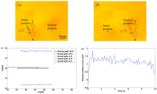
Figure 9.
Experiments of translation movement of microtool. (a) Initial position. (b) Desired position. (c) Desired and actual transport paths. The black dotted line denotes the desired path of the microtool center OR, and the red line indicates the actual path of OR (d) Absolute position errors of the microtool center OR transport.
3.1.3. Rotation of Microtool
In the third experiment, we demonstrated the rotational movement of the microtool under the operation of optical tweezers. Three optical traps were created to trap the three handling spheres of the microtool, namely, A, B, and C in Figure 10. The microtool was rotated clockwise about its central point OR at an angular velocity of 0.12 rad/s. Figure 10a and b depict the initial and desired directions of the microtool, and Figure 10c illustrates the desired and actual poses of the microtool, where the black dot denotes the desired position of OR and the red dot indicates the actual path of OR. Notably, the microtool was stably rotated clockwise with the optical traps. Figure 10d shows the absolute angular errors of the microtool in transport, which is less than 0.1 rad.
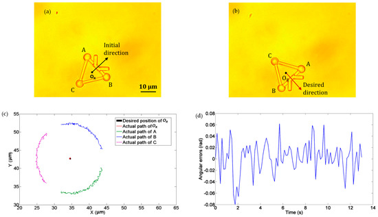
Figure 10.
Experiments of rotation movement of the microtool. (a) Initial direction. (b) Desired direction. (c) Desired and actual movement paths. The black dot denotes the desired position of OR and the red dot indicates the actual path of OR. (d) Absolute directional errors.
3.2. Transport of Cells
Experiments were performed to demonstrate the effectiveness of our approach to transporting cells. Yeast cells with diameters ranging from 4 to 6 µm were used.
3.2.1. Transport of Cells Without Obstacles
Figure 11a–d show the transportation of one yeast cell under the manipulation of the microtool operated by optical tweezers. In this experiment, no obstacle was situated in the workspace, and the desired position was marked by a star. The target cell was pushed along a straight path to the desired position at a velocity of 2.5 µm/s. During transportation, the cell remained inside the V-shaped head. Figure 11e shows the absolute cell position errors during the manipulation, the maximum of which is less than 2.5 µm.
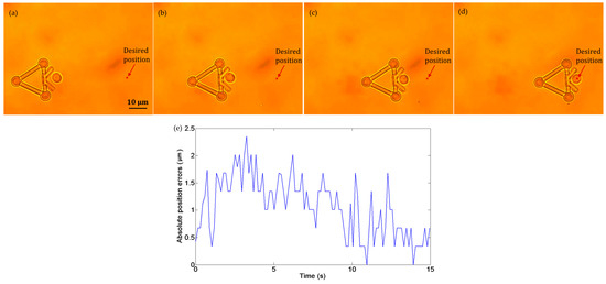
Figure 11.
Experiments of cell transport without obstacles in the workspace. (a) t = 0 s: the cell in the initial position. (b) t = 5 s: the cell in transport. (c) t = 10 s: the cell in transport. (d) t = 15 s: the cell was successfully transported to the desired position. (e) Absolute position errors of the cell in transport.
3.2.2. Transport of Cells with an Obstacle
We performed cell transportation with an obstacle in the workspace. To avoid colliding with the obstacle, the target cell was transported along a collision-free path as shown in Figure 12a–d. When the cell reached the waypoint in the path, the microtool rotated around the cell center to adjust its direction. After turning to the new direction, the microtool continued to move forward. Figure 12e illustrates absolute cell position errors, which are less than 2.5 µm. Notably, although the microtool rotated around the cell center and no push forces were exerted on the cell from 8 to 17 s, dynamic position errors still occurred. This phenomenon is mainly induced by the Brownian motion of the cell and fluctuation of the fluid around it.
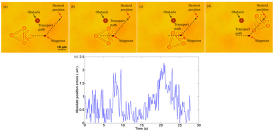
Figure 12.
Experiments of cell transport with an obstacle in the workspace. (a) t = 0 s: the cell in the initial position. (b) t = 8 s: the cell reached the waypoint in the path. (c) t = 17 s: the microtool was turned to the new direction. (d) t = 28 s: the cell was successfully transported to the desired position. (e) Absolute position errors of the cell in transport.
3.2.3. Reduced Photobleaching
Combining optical tweezers with fluorescence microscopy offers a powerful technique for studying the biochemical and biophysical properties of single cells, as well as single proteins and molecules [47,48]. By incorporating a fluorescent label, we obtained direct information with regard to the spatial and temporal distribution and evolution of particles within cells. However, such integrated technology has remained elusive due to the dramatic photobleaching on common fluorescent dyes under exposure to optical trapping and fluorescence excitation beams [49,50,51]. Therefore, establishing combined optical manipulation and fluorescence microscopy with minimal photobleaching to cells is crucial.
In this study, experiments were performed to further demonstrate that the source of photobleaching can be reduced by indirect manipulation with the proposed microtool. The mitoTracker Red probe (M7512, Invitrogen, Thermo Fisher, Waltham, MA, USA) stained yeast cells were indirectly manipulated with the microtool and directly manipulated with optical tweezers for 10 min. The output laser power from the laser source was set to 0.9 W. Fluorescence microscopy was employed to measure the fluorescence. The red dye was excited with a fluorescence illuminator (120PC Q, X-cite) and imaged with a Nikon TRITC filter cube. For each cell, the fluorescence images at different time points were captured with the same exposure setting.
For indirect manipulation, a yeast cell was trapped between the V-shaped heads of two microtools, as shown in Figure 13a. In this manner, the cells are stably captured between the two microtools and its fluorescent images could be expediently taken. Figure 13c shows that although the imaged cell shape slightly changed due to the Brownian motion, the size of the red area displayed no obvious reduction during the indirect manipulation. Additionally, the average fluorescence intensity, measured by ImageJ [52], at 10 min only dropped to 96% ± 2% (mean ± SEM) compared with that at 0 min. For direct manipulation, Figure 13d shows a series of the fluorescence images of a yeast cell that was directly trapped by optical tweezers. During the direct trapping, the posture of the cell remained unchanged. However, the size of the red area was considerably reduced. Moreover, the fluorescence intensity of the cell under direct optical manipulation dropped to 86% ± 1% (mean ± SEM) compared with that at 0 min. Figure 13b shows the time-dependent change of fluorescence intensity under direct and indirect optical manipulation. The results suggest that during the long-time trapping, indirect optical manipulation with the proposed microtool induces considerably less photobleaching to cells compared with direct optical manipulation. This finding also indicates that laser exposure to the cells is effectively reduced.
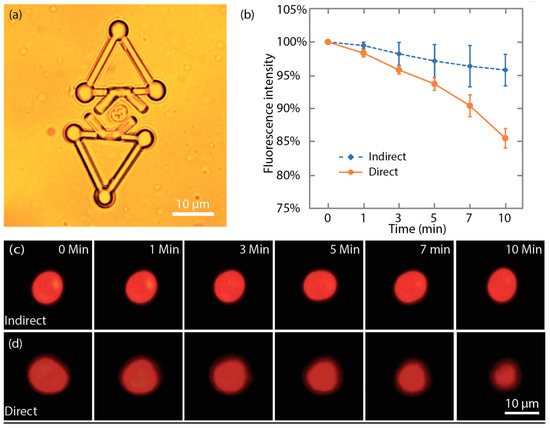
Figure 13.
Indirect optical manipulation induced less photobleaching. (a) One cell was trapped by two microtools for fluorescence imaging. (b) Plot of time-dependent change of the fluorescence intensity under direct and indirect optical manipulation. (c) Fluorescent images of the mitoTracker Red probe stained cell during the indirect optical manipulation. (d) Fluorescent images of the mitoTracker Red probe stained cell during the direct optical manipulation.
4. Conclusions and Discussion
We proposed a new approach for precise and safe cell transportation with a robot-aided HOT system and a microtool fabricated with 2PP nano printing. A control strategy combined with the imaging processing algorithm was developed for automated cell transportation. Three optical traps were employed to push cells through transporting and rotating the microtool with the control strategy and real-time visual feedback. Experiments with the yeast cells were performed to demonstrate the effectiveness of the proposed approach. Under the manipulation of the optical tweezers and microtool, the yeast cell was pushed to the desired positions by following straight paths with high precision. Experiments with fluorescence microscopy verified that indirect manipulation could induce less exposure to the cell compared with direct optical manipulation.
A limitation of the microtool-based method is that the microtool is relatively large compared with the precious workspace of the HOT. This limitation may cause the following problems: (1) The microtool is difficult to directly apply in crowded cell manipulation environments. Particularly, when a larger microtool is used to transport mammalian cells, the microtool and cell will occupy a large part of the workspace of the HOT, and the transportation space is squeezed. (2) The large size results in difficult manipulation of non-spherical cells by controlling multiple microtools cooperatively. Our future work will address the optimization of the shape and size of the microtool and the development of additional intelligent control and path planning algorithms for transportation and rotation of more cell types. In addition, specific biological applications of our approach will be studied.
Author Contributions
S.H. and H.X. contributed equally to this work. Conceptualization, S.H., H.X., S.C., and D.S.; methodology, S.H., H.X., and T.W.; software, S.H. and H.X.; validation, S.H., H.X., T.W., S.C., and D.S.; formal analysis, S.C. and D.S.; investigation, S.H. and H.X.; resources, S.H. and D.S.; data curation, S.H. and H.X.; writing—original draft preparation, S.H., H.X., and S.C.; writing—review and editing, S.H. and S.C.; visualization, S.C.; supervision, D.S.; project administration, S.H.; funding acquisition, S.H. and D.S.
Funding
This research was funded by the National Natural Science Foundation of China, grant number 61803270; Science Fund for Creative Research Groups of National Natural Science Foundation of China, grant number 51821093; Research Grants Council of the Hong Kong Special Administrative Region, China, grant number CityU 11209917.
Conflicts of Interest
The authors declare no conflict of interest.
References
- Wakamoto, Y.; Dhar, N.; Chait, R.; Schneider, K.; Signorino-Gelo, F.; Leibler, S.; McKinney, J.D. Dynamic persistence of antibiotic-stressed mycobacteria. Science 2013, 339, 91–95. [Google Scholar] [CrossRef]
- Pagliara, S.; Franze, K.; McClain, C.R.; Wylde, G.; Fisher, C.L.; Franklin, R.J.M.; Kabla, A.J.; Keyser, U.F.; Chalut, K.J. Transition from pluripotency in embryonic stem cells distinguished by an auxetic nucleus. Nat. Mater. 2014, 13, 638–644. [Google Scholar] [CrossRef] [PubMed]
- Wang, Z.; Feng, C.; Ang, W.T.; Tan, S.Y.M.; Latt, W.T. Autofocusing and polar body detection in automated cell manipulation. IEEE Trans. Biomed. Eng. 2017, 64, 1099–1105. [Google Scholar] [CrossRef] [PubMed]
- Zhang, H.; Liu, K.-K. Optical tweezers for single cells. J. R. Soc. Interface 2008, 5, 671–690. [Google Scholar] [CrossRef]
- Ashkin, A.; Schütze, K.; Dziedzic, J.M.; Euteneuer, U.; Schliwa, M. Force generation of organelle transport measured in vivo by an infrared laser trap. Nature 1990, 348, 346–348. [Google Scholar] [CrossRef]
- Wang, M.D.; Yin, H.; Landick, R.; Gelles, J.; Block, S.M. Stretching DNA with optical tweezers. Biophys. J. 1997, 72, 1335–1346. [Google Scholar] [CrossRef]
- Hu, S.; Gou, X.; Han, H.; Leung, A.Y.H.; Sun, D. Manipulating cell adhesions with optical tweezers for study of cell-to-cell interactions. J. Biomed. Nanotechnol. 2013, 9, 281–285. [Google Scholar] [CrossRef] [PubMed]
- Wang, X.; Chen, S.; Kong, M.; Wang, Z.; Costa, K.D.; Li, R.A.; Sun, D. Enhanced cell sorting and manipulation with combined optical tweezer and microfluidic chip technologies. Lab Chip 2011, 11, 3656–3662. [Google Scholar] [CrossRef] [PubMed]
- Tan, Y.; Sun, D.; Wang, J.; Huang, W. Mechanical characterization of human red blood cells under different osmotic conditions by robotic manipulation with optical tweezers. IEEE Trans. Biomed. Eng. 2010, 57, 1816–1825. [Google Scholar] [CrossRef] [PubMed]
- Schonbrun, E.; Piestun, R.; Jordan, P.; Cooper, J.; Wulff, K.D.; Courtial, J.; Padgett, M. 3D interferometric optical tweezers using a single spatial light modulator. Opt. Express 2005, 13, 3777–3786. [Google Scholar] [CrossRef] [PubMed]
- Curtis, J.E.; Koss, B.A.; Grier, D.G. Dynamic holographic optical tweezers. Opt. Commun. 2002, 207, 169–175. [Google Scholar] [CrossRef]
- Miled, M.A.; Massicotte, G.; Sawan, M. Dielectrophoresis-based integrated lab-on-chip for nano and micro-particles manipulation and capacitive detection. IEEE Trans. Biomed. Circuits Syst. 2012, 6, 120–132. [Google Scholar] [CrossRef]
- Yu, M.; Chen, Z.; Xiang, C.; Liu, B.; Xie, H.; Qin, K. Microfluidic-based single cell trapping using a combination of stagnation point flow and physical barrier. Acta Mech. Sin. 2016, 32, 422–429. [Google Scholar] [CrossRef]
- Pawashe, C.; Floyd, S.; Diller, E.; Sitti, M. Two-dimensional autonomous microparticle manipulation strategies for magnetic microrobots in fluidic environments. IEEE Tran. Robot. 2012, 28, 467–477. [Google Scholar] [CrossRef]
- Zhang, X.; Leung, C.; Lu, Z.; Esfandiari, N.; Casper, R.F.; Sun, Y. Controlled aspiration and positioning of biological cells in a micropipette. IEEE Trans. Biomed. Eng. 2012, 59, 1032–1040. [Google Scholar] [CrossRef]
- Ding, X.; Lin, S.C.; Kiraly, B.; Yue, H.; Li, S.; Chiang, I.K.; Shi, J.; Benkovic, S.J.; Huang, T.J. On-chip manipulation of single microparticles, cells, and organisms using surface acoustic waves. Proc. Natl. Acad. Sci. USA 2012, 109, 11105–11109. [Google Scholar] [CrossRef]
- Wong, C.Y.; Mills, J.K. Automation and optimization of multipulse laser zona drilling of mouse embryos during embryo biopsy. IEEE Trans. Biomed. Eng. 2017, 64, 629–636. [Google Scholar]
- Li, X.; Cheah, C.C. A simple trapping and manipulation method of biological cell using robot-assisted optical tweezers: Singular perturbation approach. IEEE Trans. Ind. Electron. 2017, 64, 1656–1663. [Google Scholar] [CrossRef]
- Kwon, J.-S.; Oh, J.H. Microfluidic technology for cell manipulation. Appl. Sci. 2018, 8, 992. [Google Scholar] [CrossRef]
- Zhong, M.-C.; Wei, X.-B.; Zhou, J.-H.; Wang, Z.-Q.; Li, Y.-M. Trapping red blood cells in living animals using optical tweezers. Nat. Commun. 2013, 4, 1768. [Google Scholar] [CrossRef]
- Xie, M.; Mills, J.K.; Wang, Y.; Mahmoodi, M.; Sun, D. Automated translational and rotational control of biological cells with a robot-aided optical tweezers manipulation system. IEEE Trans. Autom. Sci. Eng. 2016, 13, 543–551. [Google Scholar] [CrossRef]
- Hu, S.; Chen, S.; Chen, S.; Xu, G.; Sun, D. Automated transportation of multiple cell types using a robot-aided cell manipulation system with holographic optical tweezers. IEEE/ASME Trans. Mechatron. 2017, 22, 804–814. [Google Scholar] [CrossRef]
- Grier, D.G. A revolution in optical manipulation. Nature 2003, 424, 810. [Google Scholar] [CrossRef]
- Rajasekaran, K.; Samani, E.; Bollavaram, M.; Stewart, J.; Banerjee, A.G. An accurate perception method for low contrast bright field microscopy in heterogeneous microenvironments. Appl. Sci. 2017, 7, 1327. [Google Scholar] [CrossRef]
- Rasmussen, M.B.; Oddershede, L.B.; Siegumfeldt, H. Optical tweezers cause physiological damage to Escherichia coli and Listeria bacteria. Appl. Environ. Microbiol. 2008, 74, 2441–2446. [Google Scholar] [CrossRef]
- Pilát, Z.; Ježek, J.; Šerý, M.; Trtílek, M.; Nedbal, L.; Zemánek, P. Optical trapping of microalgate at 735–1064 nm: Photodamage assessment. J. Photochem. Photobiol. B-Biol. 2013, 121, 27–31. [Google Scholar] [CrossRef]
- Neuman, K.C.; Liou, G.F.; Block, S.M.; Bergman, K. Characterization of photodamage induced by optical tweezers. In Technical Digest. Summaries of Papers Presented at the Conference on Lasers and Electro-Optics, San Francisco, CA, USA, 3–8 May 1998; Conference Edition; 1998 Technical Digest Series; IEEE: Piscataway, NJ, USA, 1998; Volume 6, (IEEE Cat. No.98CH36178); pp. 203–204. [Google Scholar]
- Peterman, E.J.G.; Gittes, F.; Schmidt, C.F. Laser-induced heating in optical traps. Biophys. J. 2003, 84, 1308–1316. [Google Scholar] [CrossRef]
- Avci, E.; Yang, G. Development of a microhand using direct laser writing for indirect optical manipulation. In Proceedings of the 2016 IEEE/RSJ International Conference on Intelligent Robots and Systems, Daejeon, Korea, 9–14 October 2016. [Google Scholar]
- Thakur, A.; Chowdhury, S.; Švec, P.; Wang, C.; Losert, W.; Gupta, S.K. Indirect pushing based automated micromanipulation of biological cells using optical tweezers. Int. J. Robot. Res. 2014, 33, 1098–1111. [Google Scholar] [CrossRef]
- Arai, F.; Maruyama, H.; Sakami, T.; Ichikawa, A.; Fukuda, T. Pinpoint injection of microtools for minimaly invasive micromanipulation of microbe by laser trap. IEEE/ASME Trans. Mechatron. 2003, 8, 3–9. [Google Scholar] [CrossRef]
- Koss, B.; Chowdhury, S.; Aabo, T.; Gupta, S.K.; Losert, W. Indirect optical gripping with triplet traps. J. Opt. Soc. Am. B. 2011, 28, 982–985. [Google Scholar] [CrossRef]
- Whyte, G.; Gibson, G.; Leach, J.; Padgett, M.; Robert, D.; Miles, M. An optical trapped microhand for manipulating micron-sized objects. Opt. Express 2006, 14, 12497–12502. [Google Scholar] [CrossRef]
- Chowdhury, S.; Thakur, A.; Svec, P.; Wang, C.; Losert, W.; Gupta, S.K. Automated manipulation of biological cells using gripper formations controlled by optical tweezers. IEEE Trans. Autom. Sci. Eng. 2014, 11, 338–347. [Google Scholar] [CrossRef]
- Ta, Q.M.; Cheah, C.C. Stochastic control for orientation and transportation of microscopic objects using multiple optically driven robotic fingertips. IEEE Trans. Robot. 2019, 1–12. [Google Scholar] [CrossRef]
- Phillips, D.B.; Padgett, M.J.; Rarity, J.G.; Miles, M.J.; Simpson, S.H. Fabricating microscopic tools: Towards optically actuated micro-robotics. In Proceedings of the Advanced Fabrication Technologies for Micro/Nano Optics and Photonics VIII, San Francisco, CA, USA, 8–11 February 2015. [Google Scholar]
- Avci, E.; Yang, G. Development of micromechanisms for handling of biomaterials under laser light. In Proceedings of the 2016 12th IEEE/ASME International Conference on Mechatronic and Embedded Systems and Applications, Auckland, New Zealand, 29–31 August 2016. [Google Scholar]
- Avci, E.; Grammatikopoulou, M.; Yang, G. Laser-printing and 3D optical-control of untethered microrobots. Adv. Opt. Mater. 2017, 5, 1700031. [Google Scholar] [CrossRef]
- Gerena, E.; Régnier, S.; Haliyo, S. High-bandwidth 3-D multitrap actuation technique for 6-DoF real-time control of optical robots. IEEE Robot. Autom. Lett. 2019, 4, 647–654. [Google Scholar] [CrossRef]
- Villangca, M.J.; Palima, D.; Bañas, A.R.; Glückstad, J. Light-driven micro-tool equipped with a syringe function. Light-Sci. Appl. 2016, 5, e16148. [Google Scholar] [CrossRef]
- Aekbote, B.L.; Fekete, T.; Jacak, J.; Vizsnyiczai, G.; Ormos, P.; Kelemen, L. Surface-modified complex SU-8 microstructures for indirect optical manipulation of single cells. Biomed. Opt. Express 2016, 7, 45–56. [Google Scholar] [CrossRef]
- Hayakawa, T.; Fukada, S.; Arai, F. Fabrication of an on-chip nanorobot integrating functional nanomaterials for single-cell punctures. IEEE Trans. Robot. 2014, 30, 59–67. [Google Scholar] [CrossRef]
- Hu, S.; Hu, R.; Dong, X.; Wei, T.; Chen, S.; Sun, D. Translational and rotational manipulation of filamentous cells using optically driven microrobots. Opt. Express 2019, 27, 16475–16482. [Google Scholar] [CrossRef]
- Li, X.; Zell, A. Path following control for a mobile robot pushing a ball. IFAC Proc. Vol. 2006, 39, 49–54. [Google Scholar] [CrossRef]
- Frutiger, D.R.; Vollmers, K.; Kratochvil, B.E.; Nelson, B.J. Small, fast, and under control: Wireless resonant magnetic micro-agents. Int. J. Robot. Res. 2012, 29, 613–636. [Google Scholar] [CrossRef]
- D’Orazio, T.; Guaragnella, C.; Leo, M.; Distante, A. A new algorithm for ball recognition using circle Hough transform and neural classifier. Pattern Recognit. 2004, 37, 393–408. [Google Scholar] [CrossRef]
- Gou, X.; Han, H.C.; Hu, S.; Leung, A.Y.H.; Sun, D. Applying combined optical tweezers and fluorescence microscopy technologies to manipulate cell adhesions for cell-to-cell interaction study. IEEE Trans. Biomed. Eng. 2013, 60, 2308–2351. [Google Scholar]
- Walker, L.M.; Holm, Å.; Cooling, L.; Maxwell, L.; Öberg, Å.; Sundqvist, T.; El Haj, J.A. Mechanical manipulation of bone and cartilage cells with ‘optical tweezers’. FEBS Lett. 1999, 459, 39–42. [Google Scholar] [CrossRef]
- Jeffries, G.D.M.; Edgar, J.S.; Yiqiong, Z.; Shelby, J.P.; Christine, F.; Chiu, D.T. Using polarization-shaped optical vortex traps for single-cell nanosurgery. Nano Lett. 2007, 7, 415–420. [Google Scholar] [CrossRef]
- van Dijk, M.A.; Kapitein, L.C.; van Mameren, J.; Schmidt, C.F.; Peterman, E.J.G.; Van Dijk, M.A.; Van Mameren, J. Combining optical trapping and single-molecule fluorescence spectroscopy: Enhanced photobleaching of fluorophores. J. Phys. Chem. B 2004, 108, 6479–6484. [Google Scholar] [CrossRef]
- Brau, R.R.; Tarsa, P.B.; Ferrer, J.M.; Lee, P.; Lang, M.J. Interlaced optical force-fluorescence measurements for single molecule biophysics. Biophys. J. 2006, 91, 1069–1077. [Google Scholar] [CrossRef]
- Schindelin, J.; Arganda-Carreras, I.; Frise, E.; Kaynig, V.; Longair, M.; Pietzsch, T.; Preibisch, S.; Rueden, C.; Saalfeld, S.; Schmid, B.; et al. Fiji: An open source platform for biological image analysis. Nat. Methods 2012, 9, 676–682. [Google Scholar] [CrossRef]


© 2019 by the authors. Licensee MDPI, Basel, Switzerland. This article is an open access article distributed under the terms and conditions of the Creative Commons Attribution (CC BY) license (http://creativecommons.org/licenses/by/4.0/).