Article

Effects of Channel Outlet Configuration and Dimple/Protrusion Arrangement on the Blade Trailing Edge Cooling Performance

1
MOE Key Laboratory of Thermo-Fluid Science and Engineering, School of Energy and Power Engineering, Xi’an Jiaotong University, Xi’an 710049, China
2
School of Energy and Power Engineering, Xi’an Jiaotong University, Xi’an 710049, China
*
Author to whom correspondence should be addressed.
Appl. Sci. 2019, 9(14), 2900; https://doi.org/10.3390/app9142900
Submission received: 24 May 2019 / Revised: 17 July 2019 / Accepted: 17 July 2019 / Published: 19 July 2019
(This article belongs to the Section Energy Science and Technology)

Abstract

:
The trailing edge regions of high-temperature gas turbine blades are subjected to extremely high thermal loads and are affected by the external wake flow during operation, thus creating great challenges in internal cooling design. With the development of cooling technology, the dimple and protrusion have attracted wide attention for its excellent performance in heat transfer enhancement and flow resistance reduction. Based on the typical internal cooling structure of the turbine blade trailing edge, trapezoidal cooling channels with lateral extraction slots are modeled in this paper. Five channel outlet configurations, i.e., no second passage (OC1), radially inward flow second passage (OC2), radially outward flow second passage (OC3), top region outflow (OC4), both sides extractions (OC5), and three dimple/protrusion arrangements (all dimple, all protrusion, dimple–protrusion staggered arrangement) are considered. Numerical investigations are carried out, within the Re range of 10,000–100,000, to analyze the flow structures, heat transfer distributions, average heat transfer and friction characteristics and overall thermal performances in detail. The results show that the OC4 and OC5 cases have high heat transfer levels in general, while the heat transfer deterioration occurs in the OC1, OC2, and OC3 cases. For different dimple/protrusion arrangements, the protrusion case produces the best overall thermal performance. In conclusion, for the design of trailing edge cooling structures with lateral slots, the outlet configurations of top region outflow and both sides extractions, and the all protrusion arrangement, are recommended.

1. Introduction

The improvement in the power and efficiency of gas turbines is largely dependent on the continuous increase of turbine inlet temperature. As a result, the turbine blades are subjected to high thermal load during operation, and are prone to ablation accidents. Although the performance of materials is constantly improving, it is still far from meeting the development need of gas turbines, thus effective thermal protection technologies must be adopted. In addition to the use of thermal battier coatings [1], coolant-based efficient cooling methods are essential for releasing the blade thermal load to reduce its temperature, and further ensuring the safe operation of gas turbines [2]. Blade cooling technology mainly includes internal cooling and film cooling [3]. In internal cooling, various heat transfer augmentation methods, including jet impingement [4], U shaped turning bend [5], and rough structures [6] are usually applied, and recently the closed cycle-based steam cooling technology [7] has been developed, greatly promoting the improvement of cooling performance. Han [8] of Texas A&M University systematically summarized the researches of their laboratory in turbine blade cooling for more than 20 years, covering experiment design and testing technologies, internal composite cooling technologies, tip cooling and other aspects, and pointed out the research priorities as well as development directions.
The trailing edge is a special area in the blade and is a major consideration in the cooling design. Cunha and Chyu [9] pointed out that the heat transfer mechanism at the trailing edge was complicated and achieving efficient cooling was a challenging task. They explored the heat transfer characteristics of four typical trailing edge channels, and discussed the effects of channel configuration, rough structure, and cutback, which laid the foundation for further extensive study of trailing edge cooling performance. Cutback is an important cooling structure in the trailing edge, whose flow and heat transfer characteristics have been widely investigated. Martini et al. [10] experimentally investigated the film cooling performance of trailing edge cutback with pin fins and ribs, and obtained the heat transfer coefficient and film cooling effectiveness within the blowing ratio range of 0.2–1.25. It was concluded that the internal turbulators had important influences on the film cooling performance. Joo et al. [11] carried out numerical studies on the cutback cooling performance and analyzed the flow structures and evolution of vortices. Effendy et al. [12] discussed the effects of lip thickness on the cutback cooling performance using the DES (Detached-Eddy Simulation) method, and found that thicker lips enhanced the mixing of hot and cold fluids. Murata et al. [13] arranged teardrop dimples at the trailing edge cutback, and tested the distributions of heat transfer coefficient and film cooling effectiveness by infrared thermal imaging technology. The PIV system was also applied to obtain the flow characteristics inside dimple cavity. Accordingly, the influence of flow structure on the heat transfer was explained.
In the internal cooling of the trailing edge, various factors including channel types, lateral extraction, rotation effect, etc., should be considered to comprehensively evaluate the cooling performance. Pascotto et al. [14] constructed trailing edge internal cooling channels with lateral slots, and numerically investigated the flow structures under rotating states using the SST (Shear Stress Transfer) turbulence model. The effects of rotation number and channel orientation were involved. The results showed that the rotating state significantly changed the flow structures. Liu et al. [15] conducted experiment studies on the heat transfer characteristics of a trapezoidal trailing edge, and also considered the effect of lateral extraction. It was found that the adoption of lateral slots greatly affected the heat transfer distribution, and the heat transfer levels near the lateral slots were improved. Park et al. [16] investigated the heat transfer performance of trailing edge channels with inclined pin fin arrays. The effects of fin diameter, inclination angle and rotation number were discussed based on the distributions of heat transfer coefficient. Yang et al. [17] experimentally investigated the thermal performance of triple flow passages in the typical blade, and found that the Coriolis force had the reverse effect on the radially inward flow and outward flow. The decrease of channel orientation weakened the heat transfer level. Moreover, a heat transfer correlation was also proposed.
Arranging rough structures or turbulators is an important and effective means of heat transfer enhancement, and has been widely applied in the heat exchangers, refrigeration, electronic component cooling, etc. Therefore, in trailing edge cooling, a large number of researches have focused on the arrangement of turbulators in the internal channels to obtain better heat transfer performance. Chyu et al. [18] summarized the rough structures used in the trailing edge cooling channels, including various ribs, fins, dimples, and composite structures, and whose features and differences in the heat transfer were analyzed in detail. Wright et al. [19] compared the cooling performance of rectangular and trapezoidal channels, taking into account the effects of lateral extraction and V shaped ribs. The results showed that the heat transfer coefficient around the lateral slots was significantly improved. Armellini et al. [20] investigated the flow and heat transfer characteristics in the trailing edge channels with two kinds of fin arrangements using liquid crystal thermal imaging technology. It was suggested that arranging ribs in the main channel was more effective than in the outlet area. Rehman et al. [21] focused on the U shape cooling channels with trapezoidal cross-sections, and carried out CFD (Computational Fluid Dynamics) calculations. They found that the introduction of guide ribs changed the local flow structures and enhanced heat transfer by 40%. Zhang et al. [22] proposed a rectangular cooling channel with longitudinal crossed ribs, and numerically investigated the thermal performance within the Re range of 10,000–30,000. It was concluded that the heat transfer improvement benefited from the secondary flow generated by the rib intersection. Siddique et al. [23] arranged dimple structures on the endwalls of two-pass trailing edge channels, and discussed the effects of dimple arrangement on the heat transfer. In order to further improve the cooling performance in the trailing edge, composite cooling technologies based on various cooling methods have become a research hotspot. Taslim et al. [24] experimentally and numerically investigated the impingement cooling performance in the trailing edge channels with ribs, and analyzed the effects of jet angle and Re. Luo et al. [25] constructed cooling channels with fin–dimple/protrusion composite structures, and concluded that, after numerical investigations, the increase in the dimple/protrusion depth was helpful to improve the heat transfer enhancement. Furthermore, Ye et al. [26] numerically investigated the cooling performance of perforated blockages with inclined holes, and found that the cooling technology greatly improved heat transfer while producing high flow resistance.
According to the above literature review, a large number of researches on the trailing edge cooling performance have been conducted, and have covered various aspects, effectively promoting the development of blade cooling technology. In the actual operation of blade trialing edge, the channel outlet configuration is flexible and variable, which has a great influence on the flow and heat transfer characteristics, while this has been rarely investigated. In addition, the dimple and protrusion have been widely used in the mid-chord regions, but whose applications in the trailing edge have rarely been studied. Taken together, the investigation of dimple–protrusion composite structure and its coupling effect with channel outlet configuration in the trailing edge has not been reported in open literature. Based on the above research status, the numerical simulation model of trapezoidal cooling channels with lateral extraction slots are constructed, taking into consideration five channel outlet configurations and three dimple/protrusion arrangements. The flow structures, heat transfer distributions, average heat transfer and friction characteristics and overall thermal performances are analyzed in detail within the Re range of 10,000–100,000.

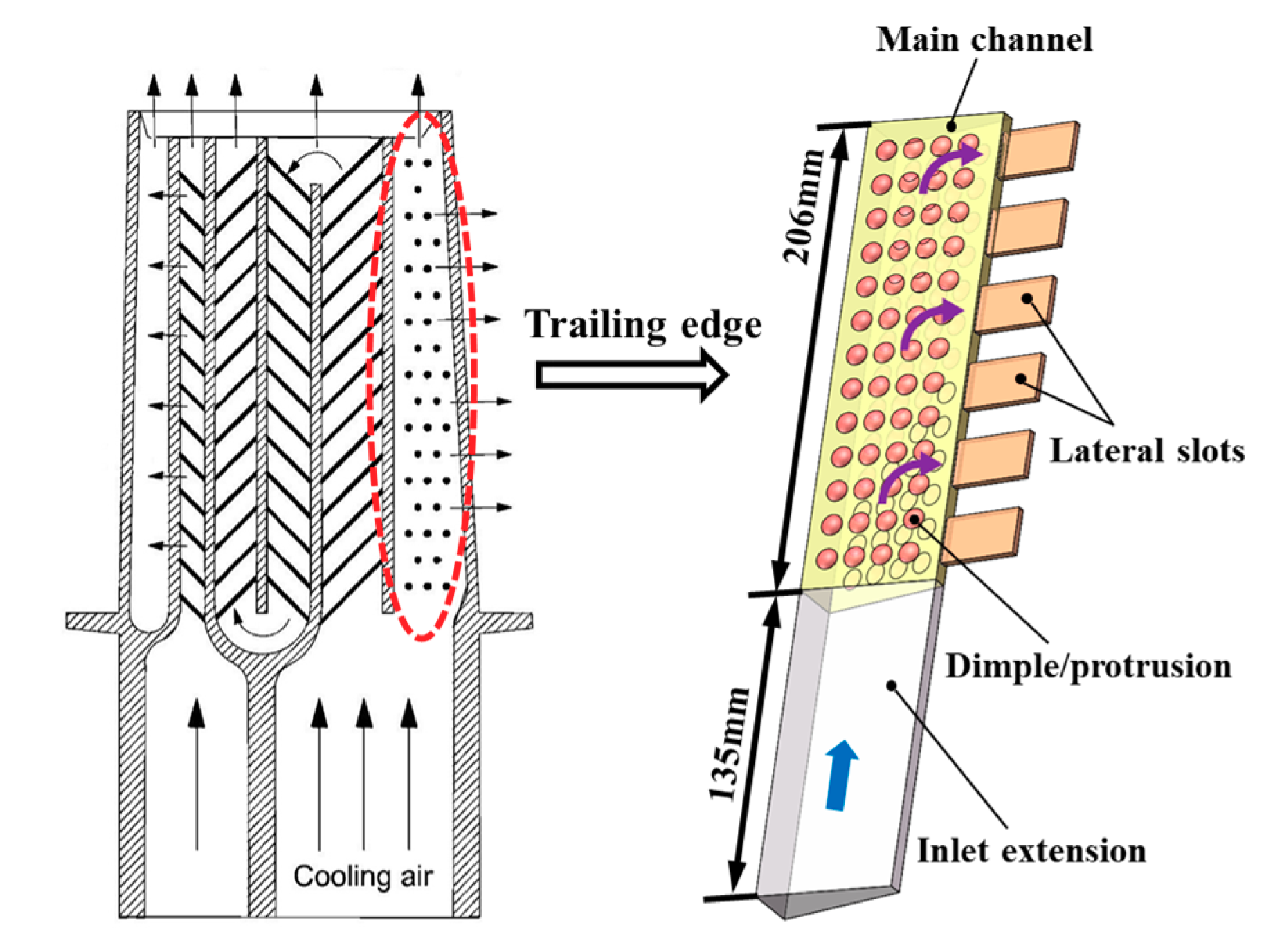
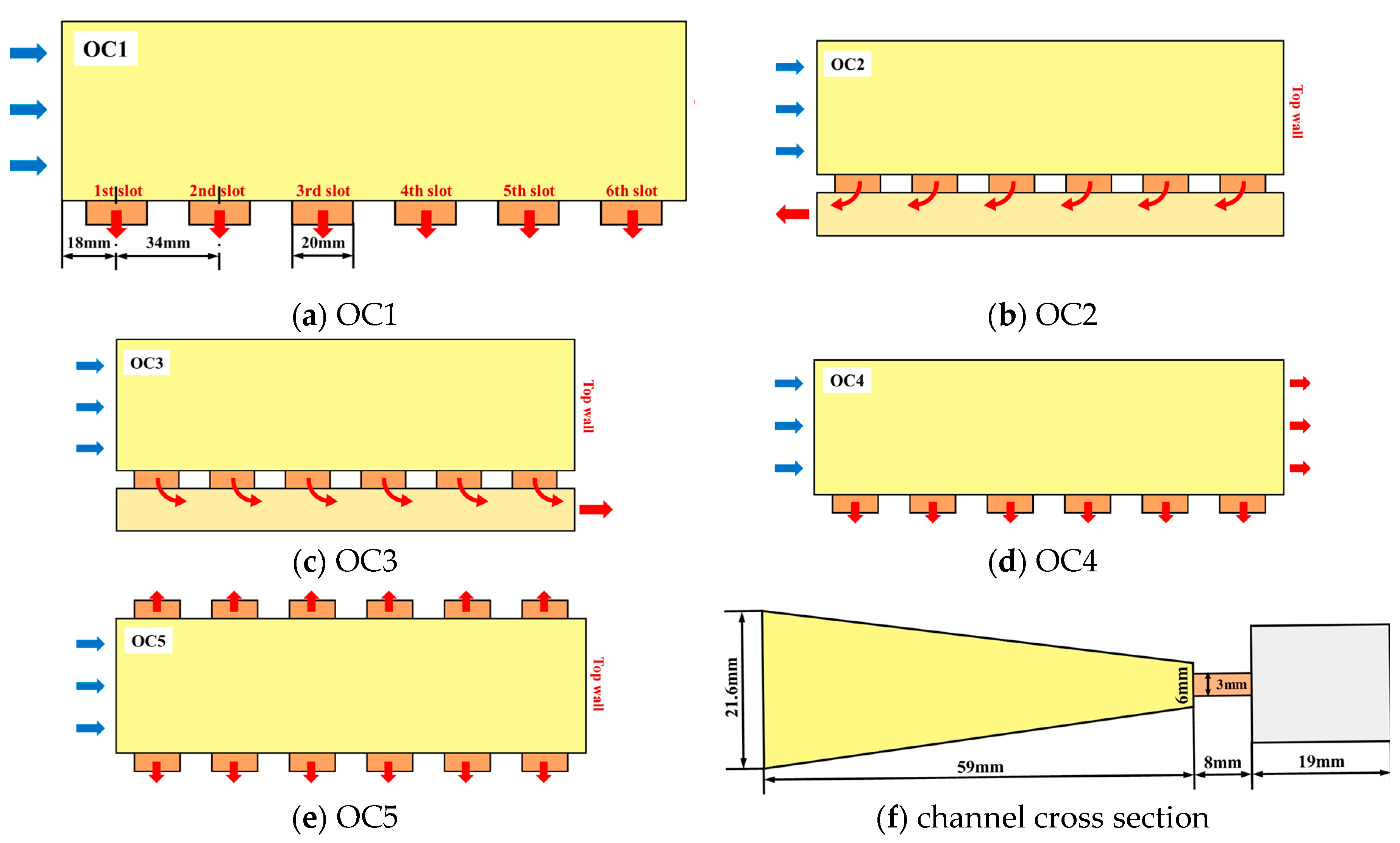
2. Research Object and Case Settings

Based on the typical internal cooling structure of turbine blades presented by Han [8], the trapezoidal trailing edge cooling channels with lateral extraction slots are modeled in this paper, shown in Figure 1. The coolant enters the channel from the bottom surface and flows through a 135 mm long inlet extension to achieve a fully developed state. Then the coolant flows into the main channel of trailing edge whose radial length is 206 mm, and the dimples/protrusions are evenly arranged on the wall of both sides. In addition, six lateral slots are set up at the short side, from which the coolant is discharged.
Figure 2 shows the structures and parameters of five channel outlet configurations, where Figure 2a is the channel without second passage (OC1), and it can be seen that six lateral slots with the width of 20 mm and the pitch of 34 mm, are evenly arranged in the radial direction; Figure 2b is the channel with radially inward flow second passage (OC2); Figure 2c is the channel with radially outward flow second passage (OC3); Figure 2d is the channel with lateral extraction and top region outflow (OC4); (e) is the channel with both sides lateral extractions (OC5). Figure 2f displays the cross section of trailing edge channel with second passage. The main channel has a cross section of isosceles trapezoid with a long side of 21.6 mm, a short side of 6mm and a height of 59 mm. The thickness and length of lateral slot are 3 and 8 mm, respectively. And the second passage has a rectangular cross section of 19 × 16 mm. It should be noted that the different outlet configurations have the same main channel, lateral slots and second passage.
Figure 3 shows the dimple/protrusion structure and arrangement in the trailing edge channels, where Figure 3a is the arrangement of dimple/protrusion, Figure 3b,c are the cross sections with dimples and protrusions, respectively. It can be seen that the inline arrangement of 4 (spanwise or axial direction) × 13 (streamwise or radial direction) is applied for dimples/protrusions, whose diameter and depth-to-diameter ratio are 9 and 0.2 mm, respectively. Four parameters P1, P2, Px, Pz, related to the layout, are 13, 9.7, 15, 12 mm, respectively. In this paper, three dimple/protrusion arrangements, i.e., all dimple (named dimple case), all protrusion (named protrusion case), dimple–protrusion staggered arrangement with the first row of dimple (named dimple–protrusion case) are considered.
Table 1 gives the case settings of this investigation, mainly including two parts. In the Part I, the effect of channel outlet configuration is studied using smooth channels, and the flow and heat transfer characteristics are analyzed for five outlet configurations within the Re range of 10,000–100,000. In the Part II, the effect of dimple/protrusion arrangement is explored based on the OC4 structure, and flow and heat transfer characteristics are discussed for three dimple/protrusion arrangements within the Re range of 10,000–100,000.

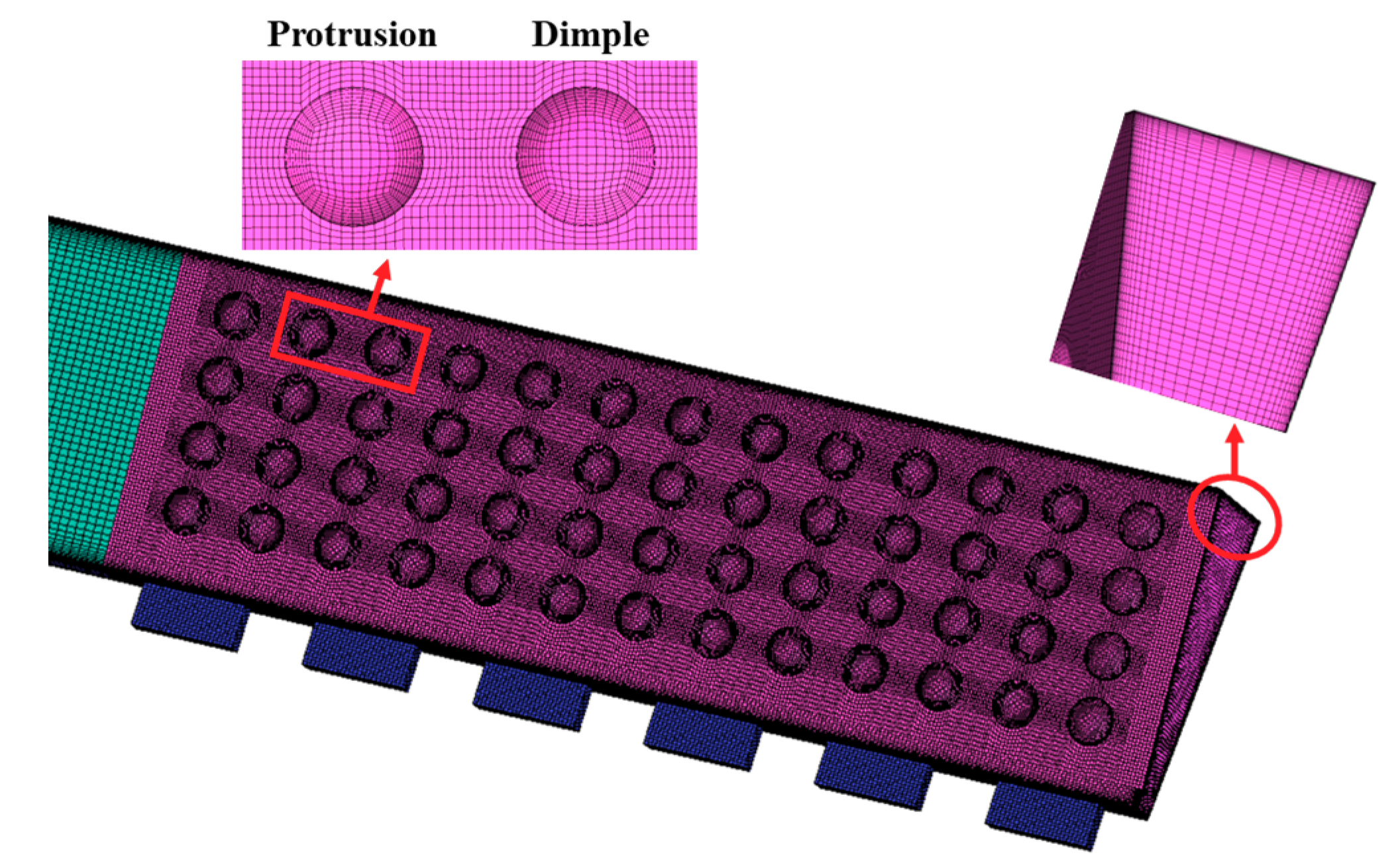
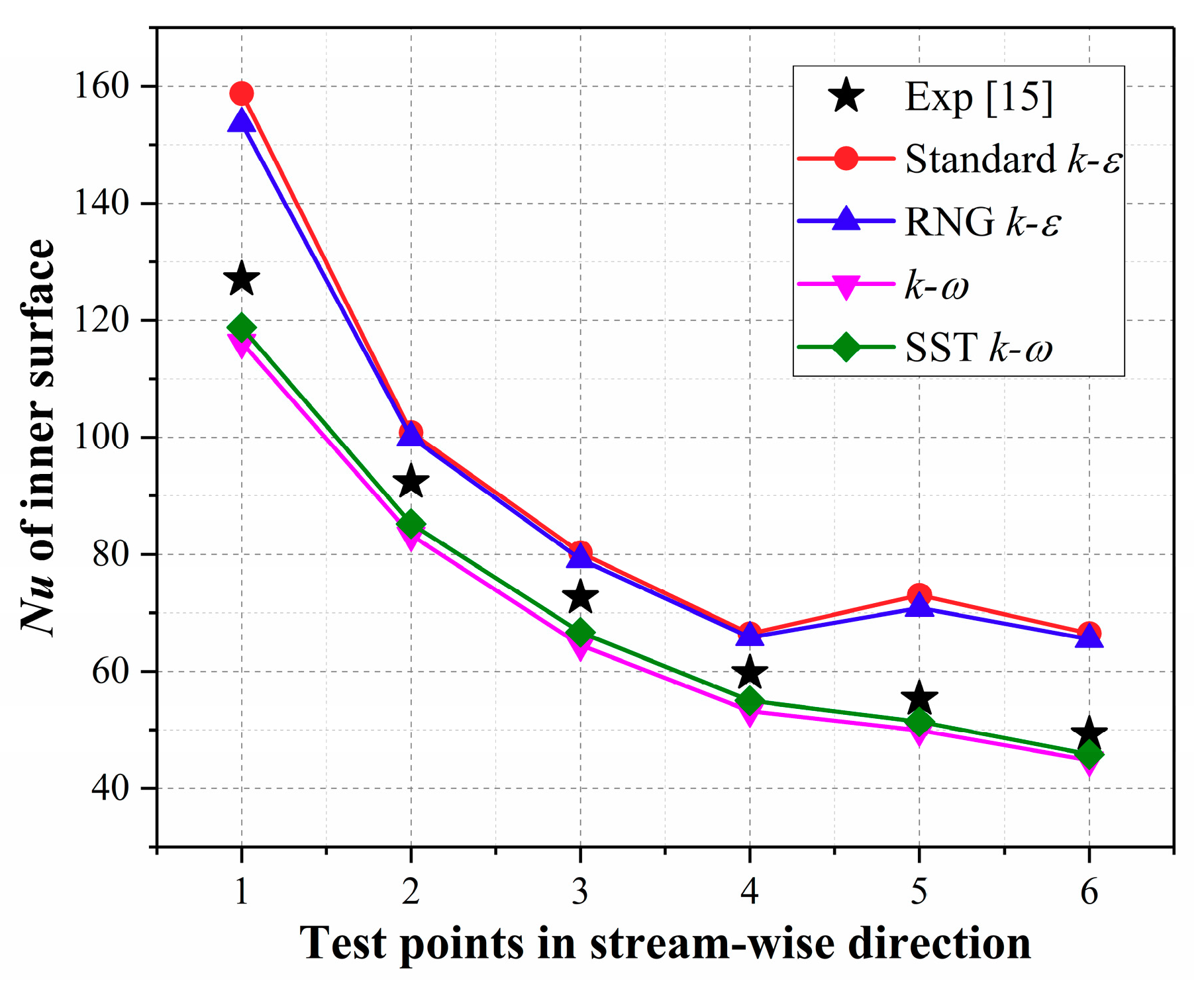
3. Numerical Method and Parameter Definition

In this paper, numerical calculations are conducted to obtain the internal flow structure, heat transfer and friction characteristics by discretely solving the continuity, momentum, and energy equations, which are performed in ANSYS CFX. The coolant is air and boundary conditions are as follows: Inlet velocity determined by Re, and the inlet temperature of 290 K; outlet pressure of 1 atm; constant heat flux on the endwalls of main channel considering that the outside walls of turbine blade are exposed to the high temperature gas environment; adiabatic boundary for the other walls. And all walls are no slip boundaries. It is worth noting that, for the OC4 case, the mass flow outlet boundary condition was applied on the lateral slots exits, and the mass flowrate of six slots was half the total mass flowrate of coolant.
Mesh is generated in ICEM platform, and the grid dependence study is conducted based on the dimple–protrusion case at the Re of 10,000 to obtain a moderate mesh number. Three grid schemes with the node number of 1283219, 2827536, and 5766132 are used, and heat transfer coefficient and pressure drop are obtained by numerical calculations, listed in Table 2. It can be found that the relative deviations of heat transfer coefficient and pressure drop between the grid scheme 2 and grid scheme 3 are 0.08% and 0.09%, respectively, which has met the accuracy requirement of heat transfer simulations. Therefore, the grid scheme 2 is adopted in this investigation. Figure 4 presents the mesh model of dimple–protrusion channel. Evidently, the O-topology is applied in the dimple/protrusion area to improve the mesh quality, and the grid is densified near the channel walls for more accurate flow and heat transfer results in the boundary layer.
This investigation is carried out within the Re range of 10,000–100,000, which is in the condition of completely turbulent flow, thus the turbulence models were validated and carefully selected. The experimental data in reference [15], which is close to the OC1 case, was extracted and compared with the numerical results by Standard k-ε, RNG k-ε, k-ω and SST k-ω models, shown in Figure 5. It can be found that the Nusselt number of the k-ω model and the SST k-ω model exhibits the similar variation as the experimental data, and the SST k-ω model presents a smaller relative deviation, within 8.2%. Moreover, literatures [14,22,25] also demonstrate that the SST k-ω model gives high simulation accuracy in the fluid flow and heat transfer of blade trailing edge. Accordingly, the SST k-ω model is applied in this paper.
The parameters involved in this study are introduced as follows.
The Reynolds number is
R e = ρ U i n D h μ
where Uin and Dh are the inlet velocity and hydraulic diameter, respectively.
The Nusselt number is
N u = h D h λ = q T w T f D h λ
where q is the wall heat flux, and Tw and Tf are the wall temperature and fluid temperature, respectively.
The friction is defined as [27]:
f = ( Δ P / L ) D h 2 ρ U i n 2
where ΔP is the pressure drop.
The overall thermal performance is
T P = ( N u / N u 0 ) ( f / f 0 ) 1 / 3
where Nu0 and f0 are the Nusselt number and friction of the smooth case.

4. Results and Discussions

4.1. Effect of Channel Outlet Configuration

Figure 6 shows the streamlines and turbulence kinetic energy (TKE) distributions on the longitudinally middle sections for five outlet configurations at the Re of 30,000. Obviously, the OC1–3 cases produce similar flow structures in the main channel, that is, the coolant flows vertically into the channel from the inlet, and is laterally deflected by the extraction slots; then the fluid obliquely impinges on the top wall and flow separation occurs, producing a teardrop shaped closed vortex in the up-right area. However, differently, the vortex area of OC2 is significantly larger than that of OC1 and OC3 cases, which is because the TKE of the second passage outlet region (that is, the inlet region of the main channel) is at a high level, thus whose pressure is lower, resulting in a stronger extraction effect and more evident flow deflection. Therefore, for the OC2 case, the impingement point on the top wall is closer to the slot side, leading to the appearance of a larger-scale vortex. While for the OC1 case, the lateral extraction effect is uniformly distributed because the pressure at each slot outlet is equal; for the OC3 case, the TKE and pressure distributions of second passage are reverse to that of the OC2 case, thus the vortex area is even slightly smaller than the OC1 case.
For the OC4 case, due to the top region outflow, the upper flow was substantially parallel to the side wall, and the lower flow was deflected by the side extraction, thus no flow separation occured and no vortex was generated in the main channel. For the OC5 case, the coolant was deflected to both sides because of the two-way lateral slots, then the fluid impingement and flow separation occurred on the central portion of the top wall, thus producing a basically symmetrical flow structure, for which no obvious vortex was generated. Furthermore, it can be found that large vortices were produced in the upstream slots; along the flow direction, the fluid deflection effect was continuously accumulated and the vortices were compressed.
Figure 7 shows the Nusselt number distributions on the endwalls for five outlet configurations at the Re of 30,000. It can be seen that, the OC1–3 cases present similar heat transfer distributions, that is, the Nu is high at the entrance area and then rapidly decreases as it flows downstream, simultaneously, the heat transfer isopleth is gradually inclined, which is consistent with the flow deflection driven by the side extraction. The semi-elliptical high-Nu regions appears between the lateral slots. Moreover, the Nu near the top wall is improved by the impingement, while the heat transfer performance in the up-right area is deteriorated due to the large closed vortex. Among the three cases, the OC2 had the largest low-Nu area, while the OC3 produced the smallest low-Nu area. For the OC4 and OC5 cases, there was no obvious heat transfer deterioration. Specifically, the top region outflow weakened the lateral extraction effect in the OC4 case, and whose Nu distribution was basically stratified along the flow direction; the local heat transfer near the top wall was enhanced in the OC5 case, while several small area heat transfer deteriorations appeared round the upper sidewall. Generally, the Nu distribution is consistent with the flow structure for all cases. The OC4 produced a higher average Nu and a smaller low-Nu area, thus has the best heat transfer performance.
Figure 8 presents the variations of Nusselt number and friction with Re for different channel outlet configurations. It can be seen from Figure 8a that, at the Re of 10,000, the Nu is close for all cases; while the Nu difference becomes obvious as the Re increases. Generally, the Nu of OC1, OC4, and OC5 increased linearly with Re, and OC4 produced the largest heat transfer augmentation within the Re range of 10,000–100,000, with the maximum Nu of 253.2. The heat transfer levels of OC1 and OC5 were relatively close, which was 2.1–13.0% lower than that of OC4 case. While for the OC2 and OC3 cases, the improvement of Nu gradually slowed down with increasing Re. Specifically, the heat transfer performances of OC3 and OC1 were at the same level within the Re range of 10,000–50,000, while the Nu of OC3 was obviously lower than that of the OC1 case when the Re reached 100,000. Among the five channel outlet configurations, OC2 presented the worst heat transfer performance, and the Nu difference between OC2 (baseline) and OC4 was up to 37.4%.
As is shown in Figure 8b, except for the friction decrease of OC1, OC2, and OC3 cases as the Re was increased from 10000 to 30000, the friction of all other cases almost remained unchanged, indicating that the Re has little effect on the flow resistance of the trailing edge channels studied in the paper. However, the flow resistance was significantly affected by the channel outlet configuration. The friction was within the range of 0.605–0.623 for the OC1 case, and was obviously increased when introducing the second passage (OC2 and OC3). The relative increment of friction factor as 35.3–40.6% for the OC2 case and 27.6–28.7% for the OC3 case, compared with the OC1 case. This was mainly caused by the impingement effect and appearance of a closed vortex, which has been described in detail in Figure 6. When the top region outflow was applied, the impingement and vortex were eliminated, thus the flow resistance was significantly reduced, which was 69.9–70.2% lower than that of the OC1 case. Additionally, the friction coefficient can be further decreased using both sides extractions (OC5). Therefore, the drag reduction effects can be effectively achieved by the top region outflow and both sides extractions.
In general, the adoption of second passage will weaken the heat transfer performance and simultaneously increase the flow resistance for the cooling of the trailing edge with lateral slots, thus thie should be avoided in practical applications; while the outlet configuration of top region outflow reduces the friction and enhances heat transfer, and is recommended as a priority in the design of the trailing edge cooling structure; although the outlet configuration of both sides extractions has a lower friction coefficient, it produced the worse heat transfer characteristics compared with the OC4, and should be considered in the light of specific circumstances.

4.2. Effect of Dimple/Protrusion Arrangement

According to the results and analysis in Section 4.1, the outlet configuration OC4 is selected due to its excellent thermal performance, and dimples/protrusions are arranged on the endwalls to further improve the heat transfer characteristics. In this section, the effect of dimple/protrusion arrangement on the trailing edge internal flow, heat transfer, flow resistance, and overall thermal performance are investigated and discussed.
Figure 9 shows the streamlines and velocity distributions on the cross sections for three dimple/protrusion arrangements at the Re of 30,000. Three cross sections, namely x/Dh = 0.8, 4.6, and 8.5 were selected, corresponding to the entrance, middle and top regions, respectively. For the dimple case, in the cross section of x/Dh = 0.8, the coolant separates at the tail region of dimple away from the extraction slots, producing several small-scale vortices, while the mainstream is little affected. As the coolant flows to the lateral slots, the extraction effect is gradually enlarged and the secondary flow near the dimples is weakened, contributing to the disappearance of flow separation at the outermost dimple. Moreover, the low-velocity areas are produced near the endwalls, especially in the dimple cavities, while the velocity around the slots is higher, and the overall flow structure and velocity distribution are substantially symmetric about the centerline. As the coolant flows downstream, the extraction effect is continuously accumulated and the affected area expands inward. Therefore, in the cross sections of x/Dh = 4.6 and 8.5, the flow separation occurred only in the innermost dimple area. At the same time, the overall flow velocity decreased and low-velocity area gradually increased.
For the protrusion case, due to the reduction of channel cross sections and the effect of impingement on the protrusion leading edge, a higher level of overall velocity, compared with the dimple case, was presented. There exist several small-scale vortices driven by the secondary flow in the leading edge of protrusions, especially for the inner protrusions. Local low-velocity area is produced on both sides of protrusions due to the weakened fluid disturbance. Similar to the dimple case, as the coolant flows downstream, the velocity of cross section gradually decreases and the secondary flow near the protrusion is weakened.
For the dimple-protrusion case, the cross sections of x/Dh = 0.8 and 4.6 were occupied by the dimples and the cross section of x/Dh = 8.5 was occupied by the protrusions. It can be seen that, in the dimple cross sections, large-scale flow separation vortices appeared in the front half of inner dimple cavity. Although a similar overall flow structure as the dimple case was presented, the velocity level was higher than the that of dimple case, demonstrating that the interaction between the dimple and protrusion effectively enhances the flow mixing. The flow structure in the protrusion cross section was close to that of protrusion case.
Figure 10 displays the Nusselt number distributions and local limiting streamlines on the endwalls for three dimple/protrusion arrangements at the Re of 30,000. As can be seen from Figure 10a, the Nu is high in the entrance area, and gradually decreases as the coolant flows downstream. Simultaneously, the high-Nu area is deflected toward the lateral slots, which is especially noticeable near the slots. According to the local limiting streamlines, the coolant separates at the leading edge of the dimple and then reattaches at the tail region, forming a separation vortex in the front half of the dimple cavity. Consequently, the Nu in the front half cavity is reduced, while the heat transfer around the dimple trailing edge as well as the downstream area is significantly improved, and this effect is gradually weakened as the coolant flows downstream.
It can be seen from Figure 10b that the overall heat transfer level on the endwalls of protrusion case is obviously higher than that of dimple case. Combined with the local limiting streamlines, the coolant impinges on the protrusion leading edge and produces a small separation region; the fluid flows downstream along the spherical protrusion surface as well as the side edges, then separates at the rear area and reattaches at the downstream region, generating a large-scale separation vortex. Therefore, the heat transfer performance on the protrusion leading edge is evidently improved attributing to the impingement effect and flow mixing, while the Nu on the tail area is reduced to a certain extent. Under the effect of lateral extraction, the abovementioned flow structure is deflected, which is particularly evident in the protrusion regions near the slots. Generally, most of protrusions are occupied by the high-Nu area, while the local heat transfer deterioration appears at the junction area of top region outflow and lateral extraction, such as the third row of protrusions near the top region.
According to Figure 10c, the local flow structures of dimple and protrusion are similar to that in Figure 10a,b. Differently, in the dimple-protrusion case, the composite flow structure was generated at the interaction of dimple and protrusion, and heat transfer enhancement area at the protrusion downstream was extended to the leading edge of dimple, but this effect was weakened along the flow direction. Moreover, it can be clearly seen that the enhanced heat transfer performance at the protrusion leading edge dropped more slowly compared with that at the dimple tail area. Consequently, the overall heat transfer performance of dimple–protrusion case is between the dimple case and protrusion case.
Variations of Nusselt number and friction with Re for different dimple/protrusion arrangements are presented in Figure 11. According to the Figure 11a, the Nu of all cases increases linearly with larger Re, among which the protrusion produced the largest Nu and the smooth case had the lowest Nu, while the heat transfer performance of dimple–protrusion case was between that of dimple and protrusion cases. Generally, at the same Re, there exists little difference in the heat transfer characteristics between different cases, and a 16.3% improvement at maximum can be achieved by the protrusion, compared with the smooth case. While in Figure 11b, significant differences in the friction for different cases can be found. As the Re is increased from 10,000 to 50,000, the friction coefficient of all cases decreases and the declining trend gradually slows down; with the further increase of Re, the friction coefficient remains almost unchanged. Relatively speaking, the smooth case had the lowest friction, followed by the dimple case, while the protrusion produced the largest flow resistance, and the friction of dimple–protrusion case was between that of dimple and protrusion cases. Compared with the smooth case, an additional friction of 8.5–10.8% was generated by the protrusion; while for the dimple case, the value was only 0.5% at maximum.
Figure 12 shows the variations of relative Nusselt number and relative friction with Re for different dimple/protrusion arrangements. It can be seen from Figure 12a that three cases present similar Nu changing regularity, that is, increases first and then decreases with larger Re, and the maximum Nu/Nu0 is obtained at the Re of 30,000. Among all cases, the protrusion produced the best enhanced heat transfer performance with the maximum Nu/Nu0 of 1.16, while the dimple case hds the lowest Nu/Nu0, whose maximum value was only 1.08, between which was the dimple–protrusion case. Within the Re range of 10,000–100,000, the f/f0 of protrusion case gradually decreased with larger Re, while the f/f0 of dimple and dimple–protrusion cases had little change, and whose relative relationship was consistent with the Nu/Nu0.
Figure 13 shows the variations of overall thermal performance with Re for different dimple/protrusion arrangements. Obviously, the TP variation law of three cases is similar to Nu/Nu0 (Figure 12a), that is, increases first and then decreases with larger Re, and the maximum TP is obtained at the Re of 30,000. This demonstrates that, the overall thermal performance of the trailing edge investigated in this paper mainly depends on the heat transfer characteristics. Moreover, the TP of dimple case and dimple–protrusion case was relatively close, while the protrusion case produced a significantly higher TP, whose maximum value reached 1.13 at the Re of 30,000, indicating a 13% improvement in the overall thermal performance compared with the smooth case. However, the TP of dimple case and dimple–protrusion case was increased by only 8.3% and 8.5% relative to the smooth case, respectively.
In general, for the cooling design of a blade trailing edge with lateral slots, the protrusion structures can significantly improve the heat transfer performance. Although additional flow resistance is produced, it still has the better overall thermal performance, compared with the dimple and dimple–protrusion cases. Therefore, the arrangement of protrusions should be given priority in practical applications.

5. Conclusions

Based on the typical internal cooling structure of a turbine blade trailing edge, trapezoidal cooling channels with lateral extraction slots were modeled in this paper. Five channel outlet configurations, i.e., no second passage (OC1), radially inward flow second passage (OC2), radially outward flow second passage (OC3), top region outflow (OC4), both sides extractions (OC5), and three dimple/protrusion arrangements (all dimple, all protrusion, dimple-protrusion staggered arrangement), were considered. Numerical investigations were carried out, within the Re range of 10,000–100,000, to analyze in detail the flow structures, heat transfer distributions, average heat transfer and friction characteristics and overall thermal performances. Specific conclusions were as follows:
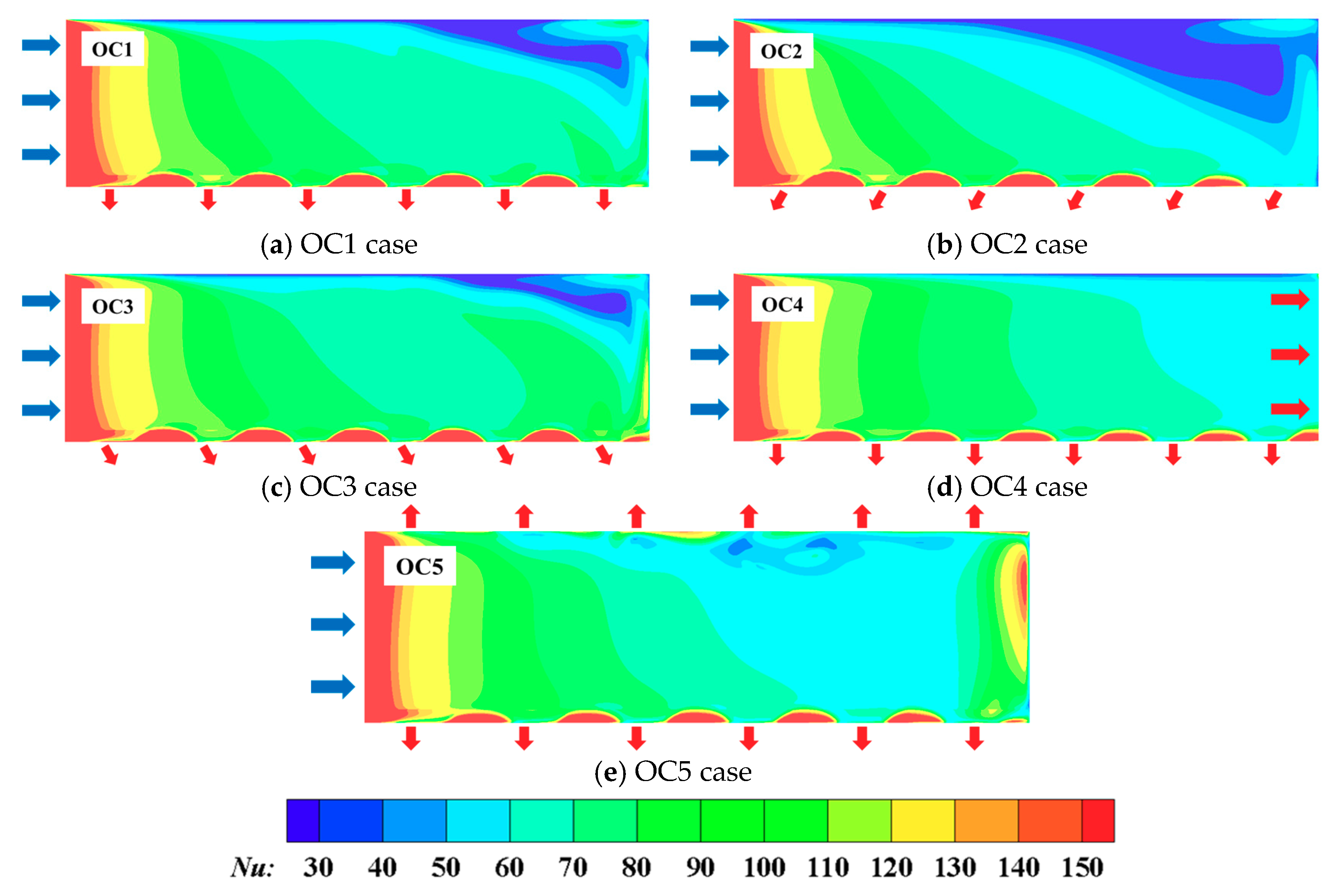
  • For five channel outlet configurations, the heat transfer level is high at the entrance area and then rapidly decreases as it flows downstream. Under the effect of lateral extraction, the coolant is deflected toward the slots, and the semi-elliptical high-Nu regions appear between the lateral slots. For the OC1, OC2 and OC3 cases, the heat transfer deterioration occurred in the up-right area due to the formation of a teardrop shaped closed vortex, which was more obvious in the OC2 case, while the heat transfer performances of OC4 and OC5 were at high levels, and OC4 produced the best heat transfer distribution;
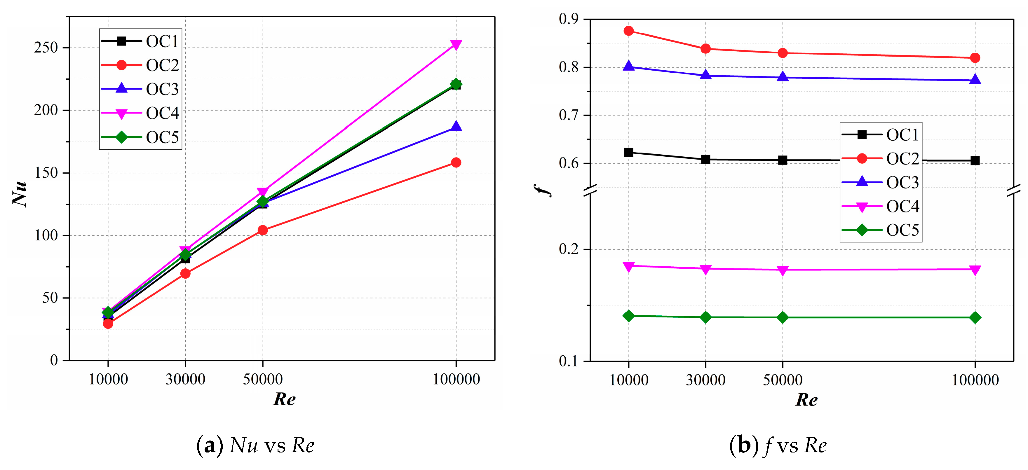
  • Among five channel outlet configurations, OC4 produced the largest heat transfer augmentation within the Re range of 10,000–100,000, with the maximum Nu of 253.2; while the OC2 presented the worst heat transfer performance, and maximum difference of Nu between OC2 and OC4 was up to 37.4%. The Re had little effect on the flow resistance of the trailing edge channels studied in the paper. Taking the OC1 case as a baseline, when introducing the second passage, the friction was significantly increased by 27.6–40.6%; when the top region outflow or both sides extractions were applied, the friction was reduced by 69.9–70.2%, or even more;
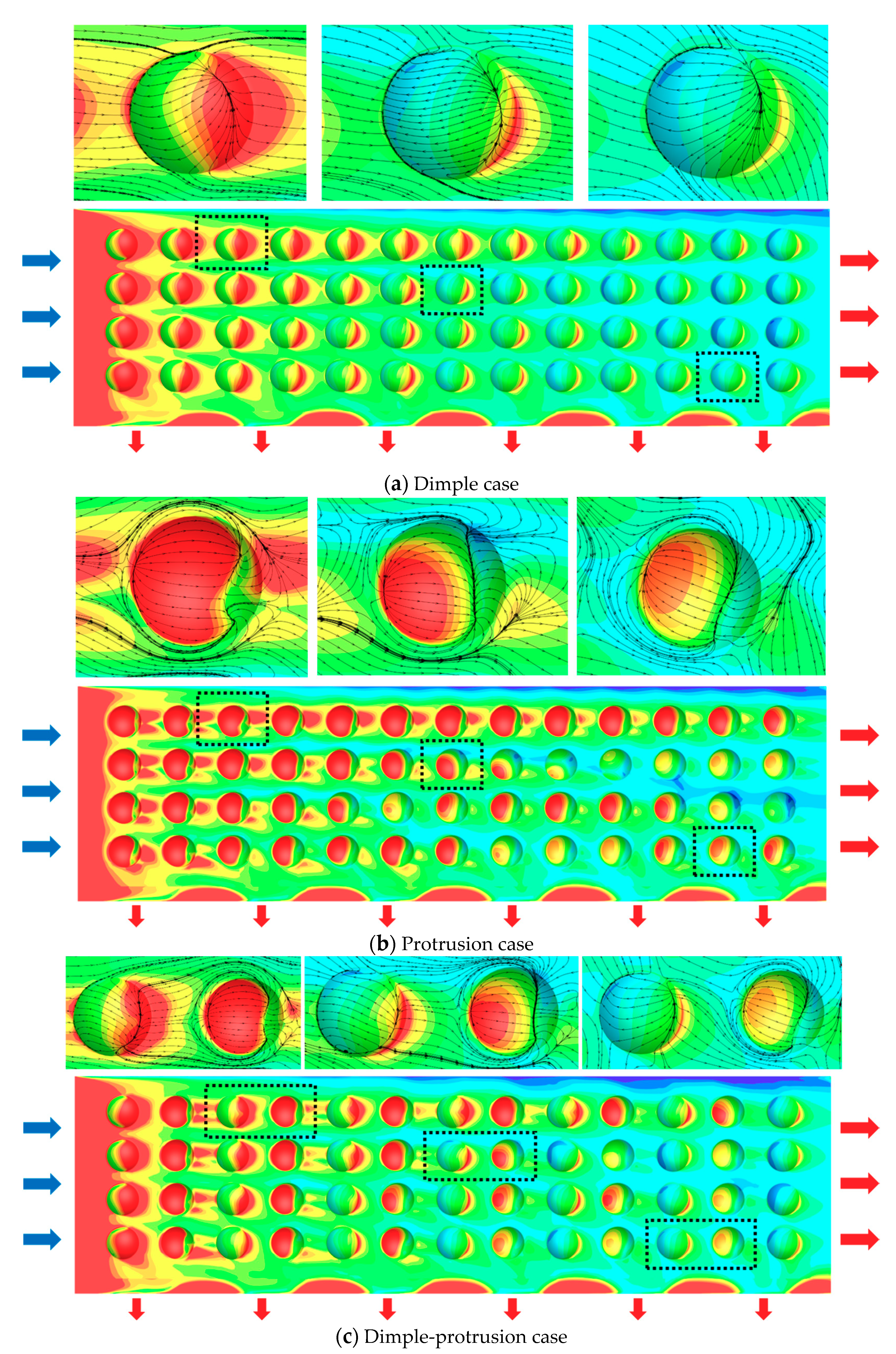
  • In the dimple area, the coolant separates at the leading edge of the dimple and then reattaches at the tail region, forming a separation vortex in the front half of the dimple cavity. In the protrusion area, the coolant impinged on the protrusion leading edge and flowed downstream along the spherical protrusion surface as well as the side edges, then separated at the rear area and reattached at the downstream region, generating a large-scale separation vortex. Therefore, the heat transfer performance in the dimple trailing edge and protrusion leading edge was greatly improved;
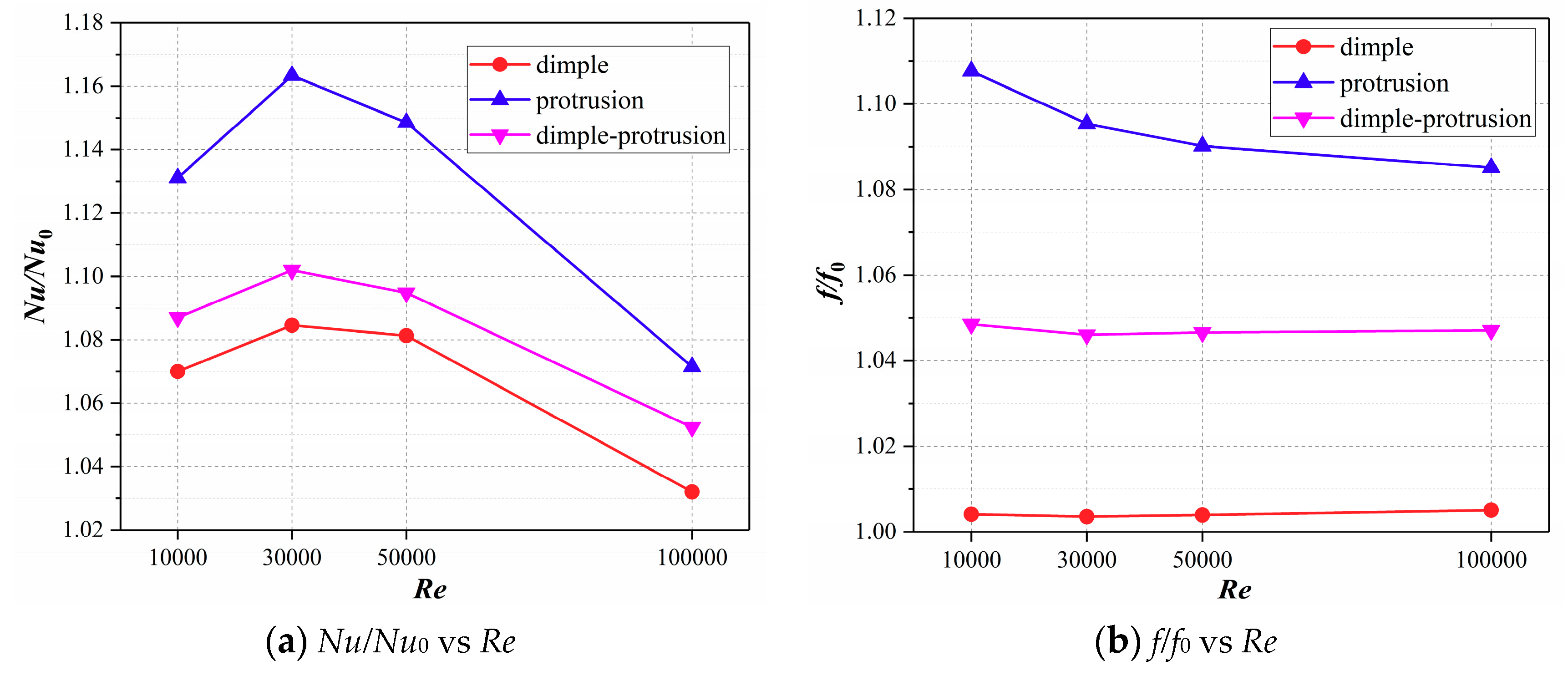
  • For different dimple/protrusion arrangements, the protrusion case produced the largest Nu, with a 16.3% improvement at maximum compared with the smooth case, simultaneously, producing an additional friction of 8.5–10.8%. The dimple case had the lowest Nu, with an only 0.5% additional friction at maximum relative to the smooth case. The heat transfer and friction characteristics of the dimple–protrusion case were between those of dimple case and protrusion case;
  • Three dimple/protrusion cases show similar TP variation law, that is, increases first and then decreases with larger Re, and the maximum TP is obtained at the Re of 30,000. The TP of the dimple case and the dimple–protrusion case was relatively close, while the protrusion case produced a significantly higher TP, whose maximum value reached 1.13, indicating a 13% improvement in the overall thermal performance compared with the smooth case.
Taken together, in the cooling design of a blade trailing edge with lateral slots, channel outlet configurations with top region outflow or both sides extractions, and the arrangement of protrusions should be given priority in practical applications. In some cases with special requirements, the optimal cooling structure should be determined by considering multiple factors, such as the blade thermal load, blade profile and radial distortion, coolant pressure and expected pressure drop, processing technology and cost.

Author Contributions

Conceptualization: Q.J., Y.X. and D.Z.; methodology: Q.J. and D.Z.; resources, Y.X. and D.Z.; software: Q.J. and Y.X.; validation: Q.J., Y.X. and D.Z.; writing—original draft: Q.J.; writing—review and editing: Q.J.

Funding

This work is supported by Research Program supported by the 111 project (B16038), China.

Conflicts of Interest

The authors declare no conflict of interest.

References

  1. Ziaei-Asl, A.; Ramezanlou, M.T. Thermo-mechanical behavior of gas turbine blade equipped with cooling ducts and protective coating with different thicknesses. Int. J. Mech. Sci. 2019, 150, 656–664. [Google Scholar] [CrossRef]
  2. Han, J.C.; Dutta, S.; Ekkad, S. Gas Turbine Heat Transfer and Cooling Technology; CRC Press: Boca Raton, FL, USA, 2012. [Google Scholar]
  3. Bogard, D.G.; Thole, K.A. Gas turbine film cooling. J. Propul. Power 2006, 22, 249–270. [Google Scholar] [CrossRef]
  4. Chi, Z.; Kan, R.; Ren, J.; Jiang, H. Experimental and numerical study of the anti-crossflows impingement cooling structure. Int. J. Heat Mass Transf. 2013, 64, 567–580. [Google Scholar] [CrossRef]
  5. Saha, K.; Acharya, S. Effect of bend geometry on heat transfer and pressure drop in a two-pass coolant square channel for a turbine. J. Turbomach. 2013, 135, 021035. [Google Scholar] [CrossRef]
  6. Shen, Z.; Qu, H.; Zhang, D.; Xie, Y. Effect of bleed hole on flow and heat transfer performance of U-shaped channel with dimple structure. Int. J. Heat Mass Transf. 2013, 66, 10–22. [Google Scholar] [CrossRef]
  7. Liu, J.; Gao, J.; Gao, T.; Shi, X. Heat transfer characteristics in steam-cooled rectangular channels with two opposite rib-roughened walls. Appl. Therm. Eng. 2013, 50, 104–111. [Google Scholar] [CrossRef]
  8. Han, J.C. Turbine blade cooling studies at Texas A&M University: 1980–2004. J. Thermophys. Heat Tr. 2006, 20, 161–187. [Google Scholar]
  9. Cunha, F.; Chyu, M.K. Trailing-edge cooling for gas turbines. J. Propul. Power 2006, 22, 286–300. [Google Scholar] [CrossRef]
  10. Martini, P.; Schulz, A.; Bauer, H.J. Film cooling effectiveness and heat transfer on the trailing edge cutback of gas turbine airfoils with various internal cooling designs. J. Turbomach. 2006, 128, 196–205. [Google Scholar] [CrossRef]
  11. Joo, J.; Durbin, P. Simulation of turbine blade trailing edge cooling. J. Fluid. Eng. 2009, 131, 021102. [Google Scholar] [CrossRef]
  12. Effendy, M.; Yao, Y.; Yao, J.; Marchant, D. DES study of blade trailing edge cutback cooling performance with various lip thicknesses. Appl. Therm. Eng. 2016, 99, 434–445. [Google Scholar] [CrossRef] [Green Version]
  13. Murata, A.; Yano, K.; Hanai, M.; Saito, H.; Iwamoto, K. Arrangement effects of inclined teardrop-shaped dimples on film cooling performance of dimpled cutback surface at airfoil trailing edge. Int. J. Heat Mass Transf. 2017, 107, 761–770. [Google Scholar] [CrossRef]
  14. Pascotto, M.; Armellini, A.; Casarsa, L.; Mucignat, C.; Giannattasio, P. Effects of rotation at different channel orientations on the flow field inside a trailing edge internal cooling channel. Int. J. Rotating Mach. 2013. [Google Scholar] [CrossRef]
  15. Liu, Y.H.; Huh, M.; Wright, L.M.; Han, J.C. Heat transfer in trailing-edge channels with slot ejection under high rotation numbers. J. Thermophys. Heat Tr. 2009, 23, 305–315. [Google Scholar] [CrossRef]
  16. Park, J.S.; Kim, K.M.; Lee, D.H.; Cho, H.H.; Chyu, M. Heat transfer in rotating channel with inclined pin-fins. J. Turbomach. 2011, 133, 021003. [Google Scholar] [CrossRef]
  17. Yang, S.-F.; Wu, H.-W.; Han, J.C.; Zhang, L.; Moon, H.K. Heat transfer in a smooth rotating multi-passage channel with hub turning vane and trailing-edge slot ejection. Int. J. Heat Mass Transf. 2017, 109, 1–15. [Google Scholar] [CrossRef]
  18. Chyu, M.K.; Siw, S.C. Recent Advances of Internal Cooling Techniques for Gas Turbine Airfoils. J. Therm. Sci. Eng. Appl. 2013, 5. [Google Scholar] [CrossRef]
  19. Wright, L.; Gohardani, A. Effect of coolant ejection in rectangular and trapezoidal trailing-edge cooling passages. J. Thermophys. Heat Transf. 2009, 23, 316–326. [Google Scholar] [CrossRef]
  20. Armellini, A.; Casarsa, L.; Mucignat, C. Experimental assessment of the aero-thermal performance of rib roughened trailing edge cooling channels for gas turbine blades. Appl. Therm. Eng. 2013, 58, 455–464. [Google Scholar] [CrossRef]
  21. Rehman, M.U.; Siddique, W.; Haq, I.; Ali, N.; Farooqi, Z. CFD analysis of the influence of guide ribs/vanes on the heat transfer enhancement of a trapezoidal channel. Appl. Therm. Eng. 2016, 102, 570–585. [Google Scholar] [CrossRef]
  22. Zhang, C.; Wang, Z.; Kang, J. Flow and Heat Transfer in a High-Aspect-Ratio Rib-Roughed Cooling Channel with Longitudinal Intersecting Ribs. J. Appl. Mech. Tech. Phys. 2018, 59, 679–686. [Google Scholar] [CrossRef]
  23. Siddique, W.; Khan, N.A.; Haq, I. Analysis of numerical results for two-pass trapezoidal channel with different cooling configurations of trailing edge: The effect of dimples. Appl. Therm. Eng. 2015, 89, 763–771. [Google Scholar] [CrossRef]
  24. Taslim, M.; Fong, M. Experimental and numerical crossover jet impingement in a rib-roughened airfoil trailing-edge cooling channel. J. Turbomach. 2013, 135, 051014. [Google Scholar] [CrossRef]
  25. Luo, L.; Qiu, D.; Du, W.; Sundén, B.; Wang, Z.; Zhang, X. Surface temperature reduction by using dimples/protrusions in a realistic turbine blade trailing edge. Numer. Heat Tr. A-Appl. 2018, 74, 1265–1283. [Google Scholar] [CrossRef] [Green Version]
  26. Ye, Y.; Li, X.; Ren, J.; Jiang, H. Split of heat transfer regions and flow characteristics of perforated blockages with inclined holes for trailing edge cooling. Numer. Heat Tr. A-Appl. 2019, 75, 21–35. [Google Scholar] [CrossRef]
  27. Chung, H.; Park, J.S.; Park, S.; Choi, S.M.; Rhee, D.H.; Cho, H.H. Augmented heat transfer with intersecting rib in rectangular channels having different aspect ratios. Int. J. Heat Mass Transf. 2015, 88, 357–367. [Google Scholar] [CrossRef]
Figure 1. Typical internal cooling structure of turbine blade (left) [8] and the trailing edge cooling channels studied in this paper (right).
Applsci 09 02900 g001
Figure 2. Structures and parameters of different channel outlet configurations.
Applsci 09 02900 g002
Figure 3. Dimple/protrusion structure and arrangement in the trailing edge channels.
Applsci 09 02900 g003
Figure 4. Mesh model of dimple-protrusion channel.
Applsci 09 02900 g004
Figure 5. Comparisons between the numerical results of the OC1 case and experimental data in reference [15].
Applsci 09 02900 g005
Figure 6. Streamlines and TKE distributions on the longitudinally middle sections for different outlet configurations, Re = 30,000.
Applsci 09 02900 g006
Figure 7. Nusselt number distributions on the endwalls for different outlet configurations, Re = 30,000.
Applsci 09 02900 g007
Figure 8. Variations of Nusselt number and friction with Re for different channel outlet configurations.
Applsci 09 02900 g008
Figure 9. Streamlines and velocity distributions on several cross sections for different dimple/protrusion arrangements, Re = 30,000.
Applsci 09 02900 g009
Figure 10. Nusselt number distributions and local limiting streamlines on the endwalls for different dimple/protrusion arrangements, Re = 30,000.
Applsci 09 02900 g010
Figure 11. Variations of Nusselt number and friction with Re for different dimple/protrusion arrangements.
Applsci 09 02900 g011
Figure 12. Variations of relative Nusselt number and relative friction with Re for different dimple/protrusion arrangements.
Applsci 09 02900 g012
Figure 13. Variations of overall thermal performance with Re for different dimple/protrusion arrangements.
Applsci 09 02900 g013
Table 1. Case settings of this investigation.
CaseOutlet ConfigurationSurface StructureRe (104)
Part IOC1smooth1/3/5/10
OC2
OC3
OC4
OC5
Part IIOC4dimple1/3/5/10
protrusion
dimple-protrusion
Table 2. Grid dependence study with dimple-protrusion case, Re = 10,000.
Grid SchemeNode Numberh (W·m−2·K−1)Error (%)ΔP/l (Pa·m−1)Error (%)
1128321948.310.56483.870.59
2282753648.580.08486.730.09
3576613248.62/487.18/

