1. Introduction
The performances of the servo motor and the motor control strategy determine the quality of the servo system. Permanent magnet synchronous motor (PMSM) has lots of merits, including high reliability and good control performance. Additionally, it has been applied in industrial robot application widely [
1,
2,
3,
4,
5,
6,
7]. Field-oriented control (FOC) and direct torque control (DTC) are the two widely applied high-performance control strategies for the PMSM [
8,
9,
10,
11,
12,
13]. Torque is the variable in DTC that is controlled directly, so the quickest dynamic response can be obtained in the PMSM driven by DTC [
14,
15,
16]. Therefore, the servo system that is composed by the permanent magnet synchronous motor (PMSM) driven by direct torque control owns many merits than other servo systems.
The torque error and the flux error are compensated by a single active vector comprehensively in single vector error compensational strategy (SV-DTC). Therefore, the PMSM driven by SV-DTC suffers from some drawbacks, such as large torque and flux linkage ripples as the errors of flux linkage and torque in conventional DTC (CDTC) are compensated by only one active vector [
17,
18,
19,
20]. On the other hand, in order to improve the steady-state performance of the PMSM, the novel direct torque control (NDTC) utilizing composite active vectors has been proposed in [
2]. Despite the better steady-state and dynamic-state performance of the PMSM system can be obtained, the computation burden is inevitably increased with the using of the adaptive sector division criterion, therefore, the fixed sector division criterion is proposed for the control system (FS-DTC) in [
3].
In order to simplify the complexity of the control system, the determination method of the duty ratio value is studied in this paper.The analytical relationship between the sector angle of the synthetic vector and the error rate is deduced first. It should be noted that the applied master vector and slave vector during each control period in FS-DTC are the adjacent vectors, therefore, the direction of the equivalentsynthetic vector is between from the directions of the two active vectors. The precondition of the accurate duty ratio value determination is the selection of the suitable discrete duty ratio value. The complexity of the control system will be increased while the discrete duty ratio value is much accurate, on the other hand, the required error compensation results cannot be obtained while the discrete duty ratio value is inaccurate. The proposed discrete duty ratio determination method can solve the existing problems in FS-DTC effectively.
The rest of this paper comprises the following sections. The calculations of the accurate active factors are described in
Section 2. The scheme diagram of the discrete duty ratio determination method is illustrated in
Section 3. The calculation for the synthetic vector, the discrete sector angle, the discrete error angle, and the duty ratio scale are also described in this Section, which are the indispensable integral parts of the discrete duty ratio determination method. The description of experimental setup and discussions on experimental results are given in
Section 4. The conclusion is analyzed in
Section 5.
2. Calculating the Accurate Active Factors
In the proposed novel direct torque control (NDTC) scheme in [
2], two active vectors are applied in one control period, which can improve the steady-state performance of the control system effectively. Additionally, the fixed sector division criterion is proposed for NDTC (FS-DTC), which can classify the complexity of the control system [
3], as shown in
Figure 1. It is also shown in
Figure 1 that the proposed discrete duty ratio determination method in this paper is used to replace the traditional duty ratio determination method in FS-DTC.
As the main errors can be compensated by the applied active vector in SV-DTC [
2], the applied two active vectors in FS-DTC are classified as master vector and slave vector [
3]. Consequently, the active angle of the master vector and the slave active vector in FS-DTC are defined as
θsm and
θss, respectively, as shown in
Figure 2.
Therefore, the active factors of torque error and flux error supplied by the master vector in
Figure 1 can be calculated as:
Consequently, the active factors of torque error and flux error supplied by the slave vector can be calculated as:
The relationships among the active vectors and the variables of the PMSM can be described as
where
dm and
ds are the duty ratio values of the master vector and the slave vector, respectively.
rT and
rF are the torque error rate and the flux error rate, respectively, which can be obtained by
where
CT and
CF are the max compensations of torque error and flux error supplied by the active vector, respectively.
From the aforementioned analyses, it can be observed that Equation (5) is the binary system of linear Equations, which will inevitably increase the computation burden of the control system.
3. Analysis of the Analytical Relationships of the Synthetic Vector
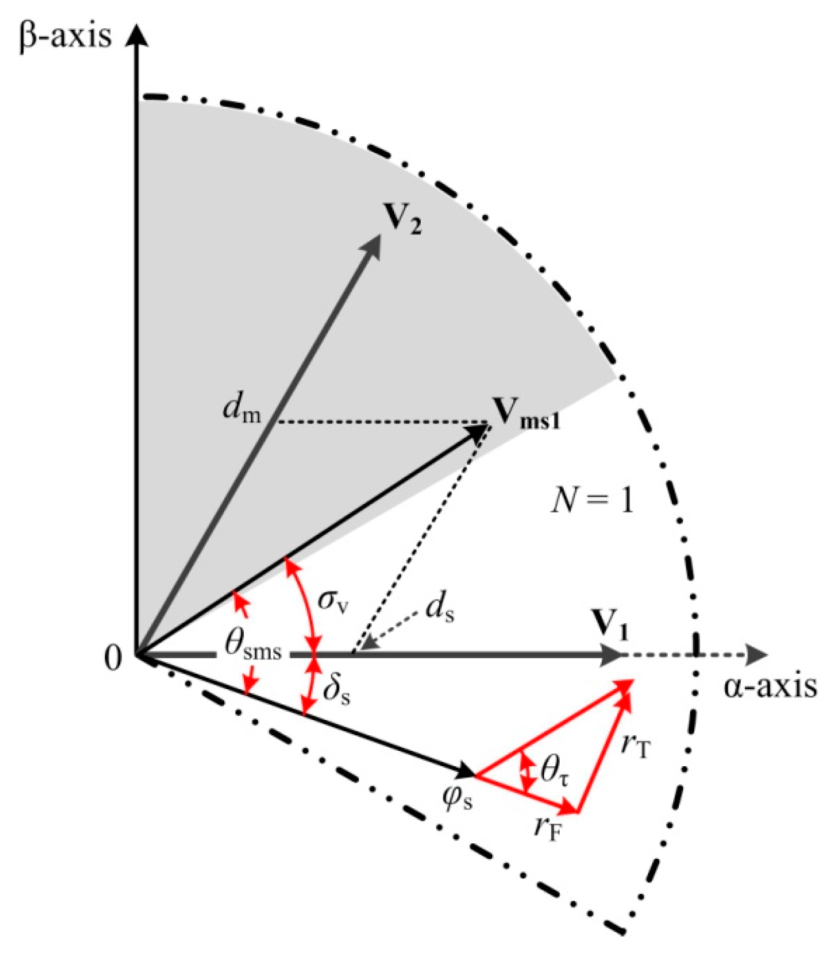
3.1. Analysis of the Synthetic Vector
The stator flux linkage
φs is located in sector 1, and the impact angle is
δs, as shown in
Figure 3.
The master vector
V2 and the slave vector
V1 will be selected to compensate the errors of the PMSM according to the selection rules of the master vector and the slave vector in FS-DTC [
3]. It is worth mentioning that the selected master vector and slave vector in each control period are the adjacent vectors. Therefore, the direction of the equivalentsynthetic vector is between the directions of the master vector and the slave vector.
Figure 3 shows that the principal of the accurate error compensation is that the direction of the synthetic vector is the same as that of the errors of the PMSM. Therefore, the relationship between the active angle of the synthetic vector and the error angle can be described as:
where
θsms is the active angle of thesynthetic vector, which can be calculated as:
The error angle
θτ can be calculated as:
where
τ is the state value of the error rate, which can be expressed as:
As the variation range of the sector angle
σv is [0°, 60°), the sector angle that can be used in the whole rotation space of the stator flux linkage can be described as
where
NN is the sector number of the phase-lag active vector,
Ns is the sector number where the stator flux linkage located in.
3.2. Calculation of the Discrete Sector Angle
The suitable discrete value of the duty ratio is approximately 0.1 [
9,
10,
11,
12,
13]. In this paper, the discrete value of the duty ratio is defined as 1/12, therefore, the discrete values including 12 synthetic vectors (
Vmsi) and 12 sector angle (
σvi) can be obtained. In this case, the value of
i varies within the range from 0 to 11, and the value of
i is an integer. The discrete voltage vector results are shown in
Figure 4.
The discrete values of the master vector and the slave vector are im and is, respectively. Furthermore, the duty ratio values of the master vector and the slave vector are dm and ds, respectively, and the sum of duty ratio values of the two active vectors is 1.
The discrete values of the sector angle under different duty ratio values of the master vector and the slave vector can be determined according to
Figure 4, as shown in
Table 1.
3.3. Calculation of the Discrete Error Angle
The discrete value of the sector angle of the synthetic vector is 5° approximately according to the discrete sector angle results in
Table 1, therefore, the discrete value of error angle can also be set as 5° according to Equation (6). The error rate is the absolute value of torque error rate and flux error rate therefore, the variation range of the error angle is (0°, 90°).
Table 2 shows the calculation results of the discrete error angle.
4. Discrete Duty Ratio Determination Method
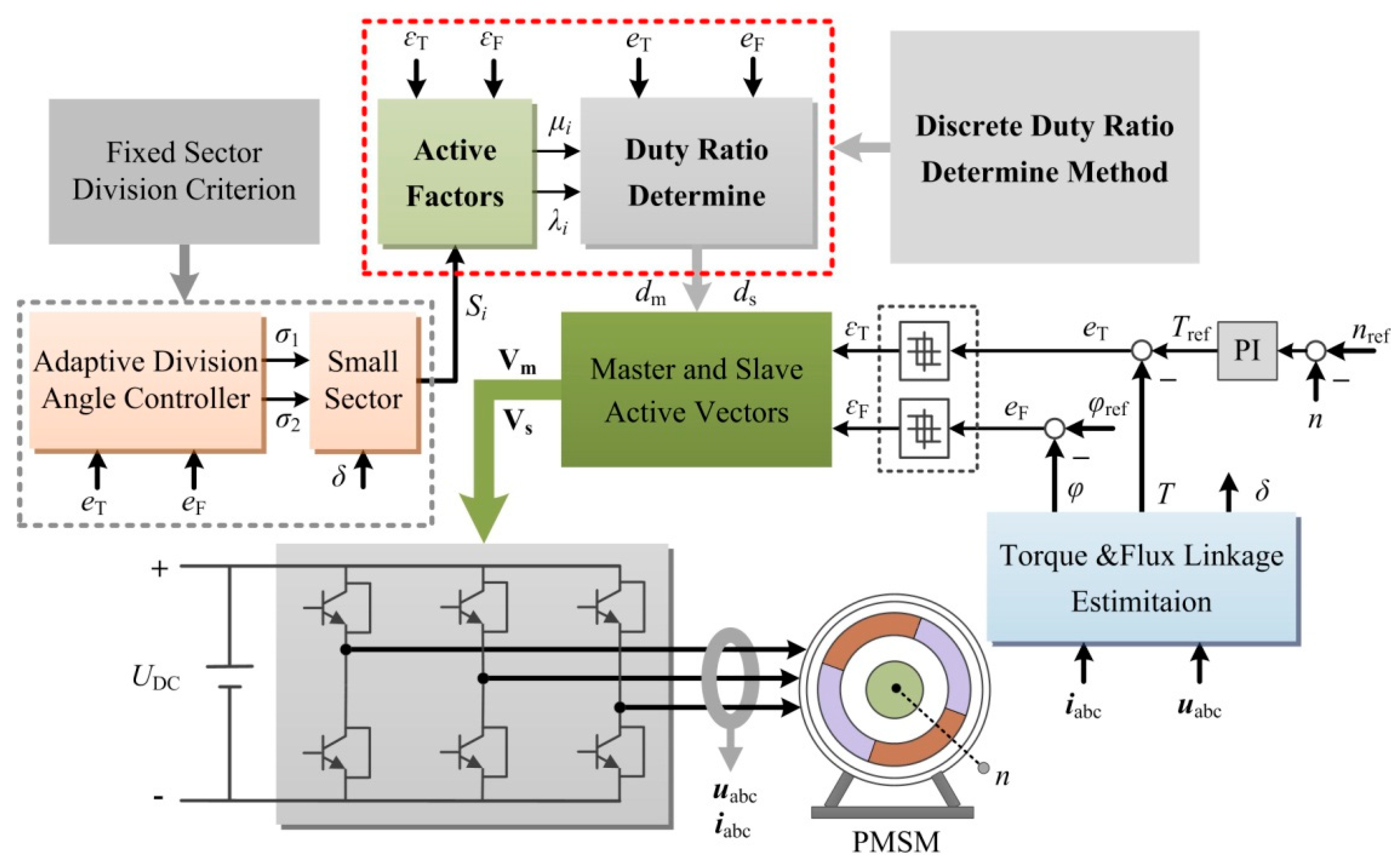
4.1. Scheme Diagram of the Discrete Duty Ratio Determination Method
In order to simplify the calculation process of the accurate duty ratio values of the master vector and the slave vector, the analytical relationship between the sector angle of the synthetic vector and the error rate is deduced in this section. Additionally, the discrete duty ratio determination method based on the discrete error angle and the duty ratio rate of the master vector and the slave vector are proposed, as shown in
Figure 5. The parameters in
Figure 5 are defined by:
dm: Duty ratio value of the master vector;
ds: Duty ratio value of the slave vector;
kms: Scale between the master vector duty ratio and the slave vector duty ratio;
θsv: Active angle of thephase-lag active vector;
rT: Torque error rate;
σv: Sector angle between the synthetic vector and the slave vector;
θτ: Error angle;
δs: Impact angle between the sector vector and the stator flux linkage φs;
NN: Sector number of the phase-lag active vector;
Ns: Sector number where the stator flux linkage located in;
Vm: Master vector;
Vs: Slave vector;
τD: Discrete value of the error rate state value;
τ: State value of the error rate.
4.2. Calculation of the Duty Ratio Scale
The scale between the master vector duty ratio and the slave vector duty ratio is defined as
The calculation process of the discrete duty ratio is described as follows:
(1) The relationship between the duty ratio scale and the sector angle of the synthetic vector is determined, as shown in
Table 3.
(2) The duty ratio scale between the applied master vector and slave vector is selected from
Table 3 according to the sector angle.
(3) The final duty ratio can be calculated based on the duty ratio scale.
As torque is the most important variable in the control system, the determination of the duty ratio values of the master vector and the slave vector should meet the prerequisites that the torque error should be compensated to the desired condition. The relationships of the variables inEquation (5) can be rewritten as
Therefore, the final duty ratio of the master vector can be calculated as
where
θsv is the active angle between the phase-lag active vector and the stator flux linkage.
Additionally, the final duty ratio of the slave vector can be calculated according to the duty ratio scale and the master vector duty ratio. It is worth mentioning that, the duty ratio of the master vector should be defined as 1, while the sum of the master vector duty ratio and the slave vector duty ratio is greater than 1, which can avoid the offset of the error compensations supplied by the two active vectors effectively.
5. Experimental Analysis
5.1. Experimental System Setup
Experimental studies are carried out on a 100-W PMSM drive system to validate effectiveness and feasibility of the discrete duty ratio determination method for FS-DTC (FS-DDTC). The experimental hardware setup is illustrated in
Figure 6.
The parameters of the PMSM are given as follows: Rs= 0.76 Ω; Ls = 0.00182 H; the number of pole pairs p = 4. The DC voltage is 36 V. The experiments are implemented in a TMS320F28335 DSP control system with a sampling period of 100 μs.
5.2. Steady-State Performance
The steady-state performances of FS-DTC and FS-DDTC are compared under the same operating condition. The PMSM is operated at 500 rpm and the reference values of torque and flux linkage are 0.8 N·m and 0.3 Wb, respectively. The torque and flux linkage waveforms of the PMSM driven by different control strategies are shown in
Figure 7, and the stator currents of the PMSM driven by two control strategies are shown in
Figure 8.
From these experimental results it can be found that, the torque ripples and the flux ripples of FS-DTC are 0.32 N·m and 0.045 Wb, respectively. The torque ripples and the flux linkage ripples of FS-DDTC are 0.35 N·m and 0.05 Wb, respectively. The total harmonic distortions of the input current ITHD of the PMSM driven by FS-DTC and FS-DDTC are 6.11% and 6.26%, respectively. Therefore, although the proposed discrete duty ratio determination method simplifies the complexity of FS-DTC, the required steady-state performance in FS-DTC will not be affected.
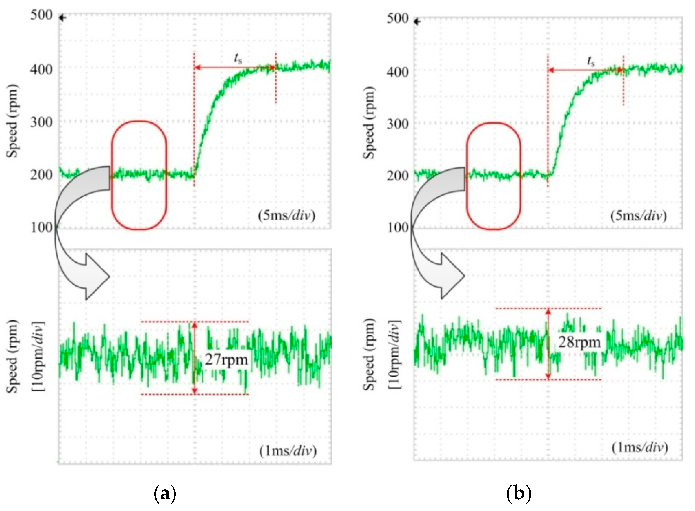
5.3. Dynamic Performance
To validate the fast dynamic response of the proposed FS-DDTC, the responses of torque and flux in the PMSM driven by the two control are tested when the torque and the flux linkage are set as 0.4 N·m and 0.3 Wb, respectively. In these tests, a step change to 100 rpm is applied on the speed reference while the PMSM is in static state, as shown in
Figure 9.
To validate the fast dynamic response of the proposed FS-DDTC, the speed responses of the PMSM driven by the two control strategies are also tested when the torque is set as 0.5 N·m. In these tests, a step change from 200 to 400 rpm is applied on the speed reference, as shown in
Figure 10.
It can be seen that the torque and the flux linkage can adjust to the settled state within the similar time, the settling time of the torque using the two different control strategies are 0.032 and 0.03 s. And the ripple of the speed is 27 rpm when using FS-DTC, while the speed ripple of the PMSM is about 28 rpm with the using of FS-DDTC. Moreover, the settling time of the rotor speed using two different control strategies are 0.015 and 0.014 s.
Therefore, the main advantage of FS-DTC, i.e., the fast dynamic response, can be maintained in the proposed FS-DDTC. The experimental results show that dynamic response owns higher priority than ripples in dynamic-state condition, hence, the accurate duty ratio determination method in FS-DTC can be abandoned.
6. Conclusions
The discrete duty ratio determination method based on the error rate is proposed in this paper. The corresponding relations between the duty ratio value of the synthetic vector and the error rate is deduced. It should be noted that the duty ratio value of the synthetic vector is the scale between the master vector duty ratio and the slave vector duty ratio. Additionally, the final duty ratio value of the master vector and the slave vector can be obtained based on the duty ratio scale value. The proposed discrete duty ratio determination method can simplify the duty ratio determination method in FS-DTC, which is the binary system of linear equations.
Experimental results clearly indicate that the FS-DDTC exhibits excellent control of torque and flux linkage with the similar steady-state ripples when compared to FS-DTC and has the same transient response performance.
Author Contributions
This paper was a collaborative effort between the authors. T.Y., D.W., X.W. (Xinghua Wang), X.W. (Xinyu Wang), S.W., and Y.N. proposed the original idea; T.Y. wrote the full manuscript and carried out the experiments.
Funding
This research was funded by National Key Research and Development Program of China under Grant 2017YFB1300900.
Acknowledgments
This work was supported in part by National Key Research and Development Program of China under Grant 2017YFB1300900.
Conflicts of Interest
The authors declare there is no conflict of interest.
References
- Yuan, T.Q.; Wang, D.Z.; Li, Y.; Yan, X.; Tan, S.; Zhou, S. Duty ratio modulation strategy to minimize torque and flux linkage ripples in IPMSM DTC system. IEEE Access 2017, 5, 14323–14332. [Google Scholar] [CrossRef]
- Yuan, T.; Wang, D.; Wang, X.; Wang, X.; Sun, Z. High-Precision servo control of industrial robot driven by PMSM-DTC utilizing composite active vectors. IEEE Access. 2019, 7, 7577–7587. [Google Scholar] [CrossRef]
- Wang, D.; Yuan, T.; Wang, X.; Wang, X.; Ni, Y. Performance improvement of servo control system driven by novel PMSM-DTC based on fixed sector division criterion. Energies 2019, 12, 2154. [Google Scholar] [CrossRef]
- Zhou, Y.; Chen, G. Predictive DTC Strategy with fault-tolerant function for six-phase andthree-phase PMSM series-connected drive system. IEEE Trans. Ind. Electron. 2018, 65, 9101–9112. [Google Scholar] [CrossRef]
- Shinohara, A.; Inoue, Y.; Morimoto, S.; Sanada, M. Direct calculation method of reference flux linkage for maximum torque per ampere control in DTC-based IPMSM drives. IEEE Trans. Power Electron. 2016, 32, 2114–2122. [Google Scholar] [CrossRef]
- Alsofyani, I.M.; Idris, N.R.; Lee, K.B. Dynamic hysteresis torque band for improving the performance of lookup-table-based DTC of induction machines. IEEE Trans. Power Electron. 2018, 33, 7959–7970. [Google Scholar] [CrossRef]
- Putri, A.K.; Rick, S.; Franck, D.; Hameyer, K. Application of sinusoidal field pole in a permanent-magnet synchronous machine to improve the NVH behavior considering the MTPA and MTPV operation area. IEEE Trans. Ind. Appl. 2016, 52, 2280–2288. [Google Scholar] [CrossRef]
- Xia, C.; Zhao, J.; Yan, Y.; Shi, T. A novel direct torque and flux control method of matrix converter-fed PMSM drives. IEEE Trans. Power Electron. 2014, 29, 5417–5430. [Google Scholar] [CrossRef]
- Mohan, D.; Zhang, X.; Foo, G.H. A simple duty cycle control strategy to reduce torque ripples and improve low-speed performance of a three-level inverter fed DTC IPMSM drive. IEEE Trans. Ind. Electron. 2017, 64, 2709–2721. [Google Scholar] [CrossRef]
- Niu, F.; Wang, B.; Babel, A.S.; Li, K.; Strangas, E.G. Comparative evaluation of direct torque control strategies for permanent magnet synchronous machines. IEEE Trans. Power Electron. 2016, 31, 1408–1424. [Google Scholar] [CrossRef]
- Zhang, Y.; Zhu, J.; Xu, W.; Guo, Y. A simple method to reduce torque ripple in direct torque-controlled permanent-magnet synchronous motor by using vectors with variable amplitude and angle. IEEE Trans. Ind. Electron. 2011, 58, 2848–2859. [Google Scholar] [CrossRef]
- Ren, Y.; Zhu, Z.Q.; Liu, J. Direct torque control of permanent-magnet synchronous machine drives with a simple duty ratio regulator. IEEE Trans. Ind. Electron. 2014, 61, 5249–5258. [Google Scholar] [CrossRef]
- Niu, F.; Li, K.; Wang, Y. Direct torque control for permanent magnet synchronous machines based on duty ratio modulation. IEEE Trans. Ind. Electron. 2015, 62, 6160–6170. [Google Scholar] [CrossRef]
- Lee, J.S.; Lorenz, R.D. Deadbeat direct torque and flux control of IPMSM drives using a minimum time ramp trajectory method at voltage and current limits. IEEE Trans. Ind. Appl. 2014, 50, 3795–3804. [Google Scholar] [CrossRef]
- Mohan, D.; Zhang, X.; Foo, G.H. Generalized DTC strategy for multilevel inverter fed IPMSMs with constant inverter switching frequency and reduced torque ripples. IEEE Trans. Energy Convers. 2017, 32, 1031–1041. [Google Scholar] [CrossRef]
- Zhang, X.; Foo, G.H. Over-modulation of constant switching frequency based DTC for reluctance synchronous motors incorporating field-weakening operation. IEEE Trans. Ind. Electron. 2019, 66, 37–47. [Google Scholar] [CrossRef]
- Berzoy, A.; Rengifo, J.; Mohammed, O. Fuzzy predictive DTC of induction machines with reduced torque ripple and high performance operation. IEEE Trans. Power Electron. 2018, 33, 2580–2587. [Google Scholar] [CrossRef]
- Choi, Y.S.; Choi, H.H.; Jung, J.W. Feedback linearization direct torque control with reduced torque and flux ripples for IPMSM drives. IEEE Trans. Power Electron. 2016, 31, 3728–3737. [Google Scholar] [CrossRef]
- Zhang, Z.; Wei, C.; Qiao, W.; Qu, L. Adaptive saturation controller-based direct torque control for permanent-magnet synchronous machines. IEEE Trans. Power Electron. 2016, 31, 7112–7122. [Google Scholar] [CrossRef]
- Liang, D.; Li, J.; Qu, R.; Kong, W. Adaptive second-order sliding-mode observer for PMSM sensorless control considering VSI nonlinearity. IEEE Trans. Power Electron. 2018, 33, 8994–9004. [Google Scholar] [CrossRef]
© 2019 by the authors. Licensee MDPI, Basel, Switzerland. This article is an open access article distributed under the terms and conditions of the Creative Commons Attribution (CC BY) license (http://creativecommons.org/licenses/by/4.0/).