Abstract
In aerospace fields and industrial sectors, high-speed centrifugal pumps are prevalent and in increasingly strict demand regarding characteristics such as the long life, small volume, light weight, and low noise. In this study, we present a novel high-speed centrifugal water pump with hydrodynamic bearings used to employ work fluid as lubricant. A three-dimensional numerical study of the turbulent fluid flow was carried out to predict the performance of the pump. The computational model was validated against experimental results during hydraulic tests. Additionally, the effect of the blade number on the head and efficiency of the pump was researched. The blade number of the impeller was changed from 4 to 8 and that of the stay vane was from 3 to 14. The results indicate that the blade number and the matching characteristic of the impeller and the stay vane significantly influenced the performance of the pump. The structure based on the seven-blade impeller and the six-blade stay vane had the highest efficiency (30.8%). Numerical investigations of this study may help reduce the significant cost and time of experimental work for a particular design.
1. Introduction
High-speed centrifugal pumps are used extensively in aerospace fields, the petrochemical industry, and the chemical industry. This is due to the advantages of high-speed centrifugal pumps’ high single-stage head, their smaller size, convenient maintenance, and reliable performance [1]. The pump driven loop heat pipe, the pump driven liquid-cooling circulation, the natural cooling system in a database, the thermal management of a small power system in aerospace fields, and other special areas, have increasing demands for small high-speed oil-free centrifugal pumps. It is well known that high-speed centrifugal pumps that adopt hard supporting structures have some drawbacks, such as a short lifespan, low efficiency, and high vibration noise. The life expectancy of a loop heat pipe in a spacecraft is only five years, whereas the demand is 10 to 15 years. To overcome the shortcomings mentioned above, two problems need to be addressed. Firstly, supporting bearings need to be optimized for the rotor in a high-speed pump. A proper supporting structure is crucial to avoid the wear and vibration noise of ball bearings and roller bearings. Secondly, the flow path in the impeller must be optimally designed to achieve the high efficiency of pumps.
In this study we propose a novel high-speed centrifugal pump with hydrodynamic bearings. The working fluid flowing into the motor path is taken as the lubricant for bearings. This structure is oil-free and pollution-free; the hard contact is eliminated at high speed, the friction vibration is weakened, and the noise is almost negligible. The volume and weight of the pump are optimized due to its high rotation speed, which is up to 9000 rpm. In addition, the heat is taken away when the fluid passes through the motor flow path, which benefits for the long-term, high-efficiency, and stable operation of the motor. The outer surface of the motor stator is sealed by the resin. Thus, the motor cavity can be used as parts of the flow path, which greatly reduces the pump volume. The traditional volute is substituted by the stay vane and guide section accordingly. The traditional one generates an axial inflow and a radial outflow, while an axial inflow and an axial outflow are guided by the new design. Although it increases the hydraulic loss, the new design will simplify the structure and reduce the size of the pump to a great extent.
Due to the advantages of the small vibration, low noise, long life, stable performance, and low wear, liquid lubricated bearings are widely researched [2,3,4,5] and used. Among all liquid lubricated bearings, water-lubricated bearings are gradually employed on tangent pumps, marine centrifugal pumps, boiler feed pumps, and so on, because it is pollution-free, non-combustible, and easy to implement. The effect of the surface roughness on the performance of water-lubricated polymer bearings was previously investigated [6]. An electronic pump supported by the water-lubricated bearing appeared in the boiler feed pump of a large scale internal-combustion engine [7]. The water-lubricated bearing was popular in marine centrifugal pumps [8]. Presently, water-lubricated bearings are generally used in medium and large-scale high-speed pumps. However, the research on their application in small scale high-speed centrifugal pumps are still few.
Researchers focus on the generalization and summarization of hydraulic models [9,10], profiles optimization of hydraulic components [11,12], and internal flow fields by CFD (Computational Fluid Dynamics) with respect to optimizing the pump flow path [13,14,15]. Liquid streamlines in pumps are in accordance with the blade profiles, under the constraint of the impeller and stay vane. Therefore, the matching relation between the impeller and stay vane with a different blade number has a strong effect on the hydrodynamic performance of pumps [16]. The design optimization of the impeller and the stay vane was numerically carried out by Kim et al. [17] and the performance improvement was obtained for the mixed-flow pump. Singh and Nestmann [18] experimentally analyzed the influence of the blade number on the performance of an axial flow turbine. They pointed out that the increased blade number will decrease the pump efficiency because of the direction change of the relative velocity at the turbine outlet. Knierim et al. [19] described an optimized process of the impeller and stay vane in a reactor coolant pump with the aid of CFD tools, which provided a theoretical guide for hydraulic design. The impact of the blade number on the head and efficiency of the low specific-speed centrifugal pump was studied by Chakraborty et al. [20]. A fully three-dimensional unsteady flow behavior within the impeller and stay vane of a centrifugal pump was revealed by Krain [21] through laser measurements. Although the influence of the blade number on the pump performance has been researched extensively, conclusions are not in accordance with each other because of the different structures of pumps. Therefore, the systematic design work needs to be conducted for a specific design.
In this paper, a novel high-speed pump with oil-free hydrodynamic bearings was proposed. A numerical model based on a steady and incompressible flow was established and assessed by comparing with experimental data. Then, the numerical studies were carried out to observe the influence of the blade number of the impeller and the stay vane on the hydraulic performance of the high-speed pump. The internal flow behavior was obtained under different computational cases. The work is expected to provide a thorough performance insight of a pump system.
2. Numerical Model
2.1. Physical Model
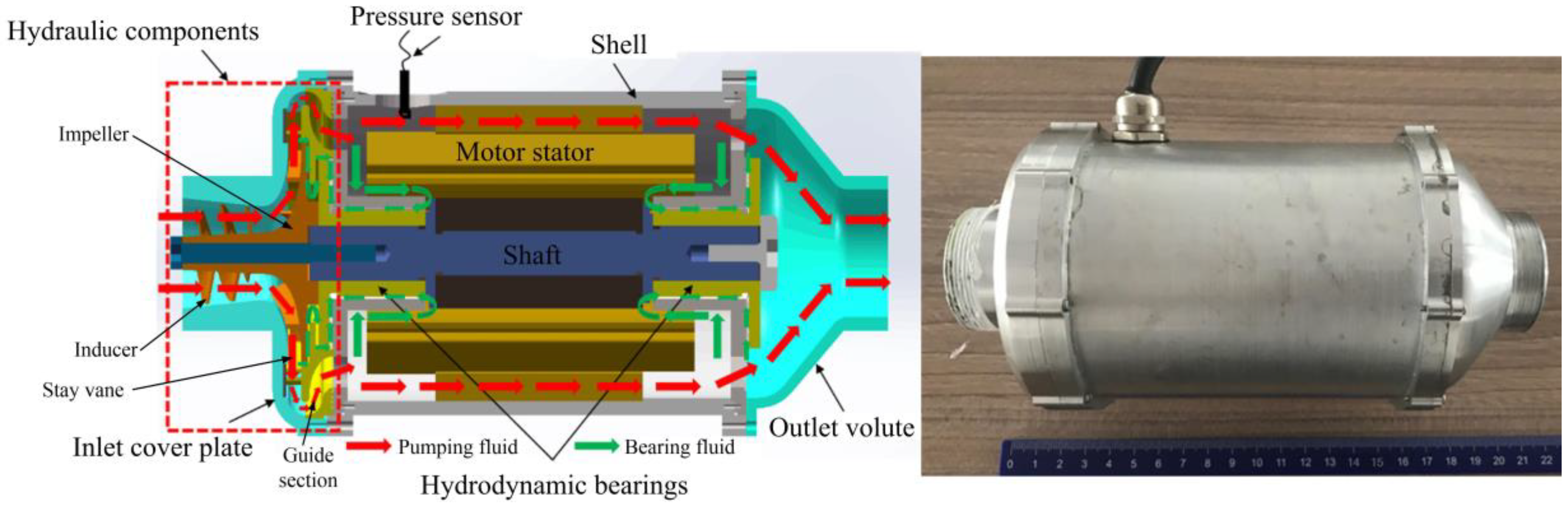
The structure of the high-speed centrifugal pump is illustrated in Figure 1 and it is comprised of rotating and stationary components. Stationary components include inlet and outlet cover plates, a stay vane, guide section, shells, a motor stator, and supporting components. Moreover, rotating components consist of an inducer, an impeller, hydrodynamic bearings, and a shaft. The flow path is formed by the cavity between the rotating and stationary components. The liquid is speeded up and its cavitation is enhanced by the high rotating inducer. After the fluid flows through the impeller, the kinetic energy of the impeller transfers into that of the fluid. In order to reduce the flow loss, the stay vane after the impeller transfers the kinetic energy of the fluid into its pressure energy. Most of the fluid enters the flow path in the motor. After cooling the motor, it is collected by the outlet cover plate. Only a small percentage of the fluid passes through the gap under the stay vane, enters into the gap in the hydrodynamic liquid lubricated bearing and provides the bearing capacity by establishing a liquid film.
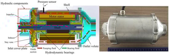
Figure 1.
Structure of the novel high-speed centrifugal pump.
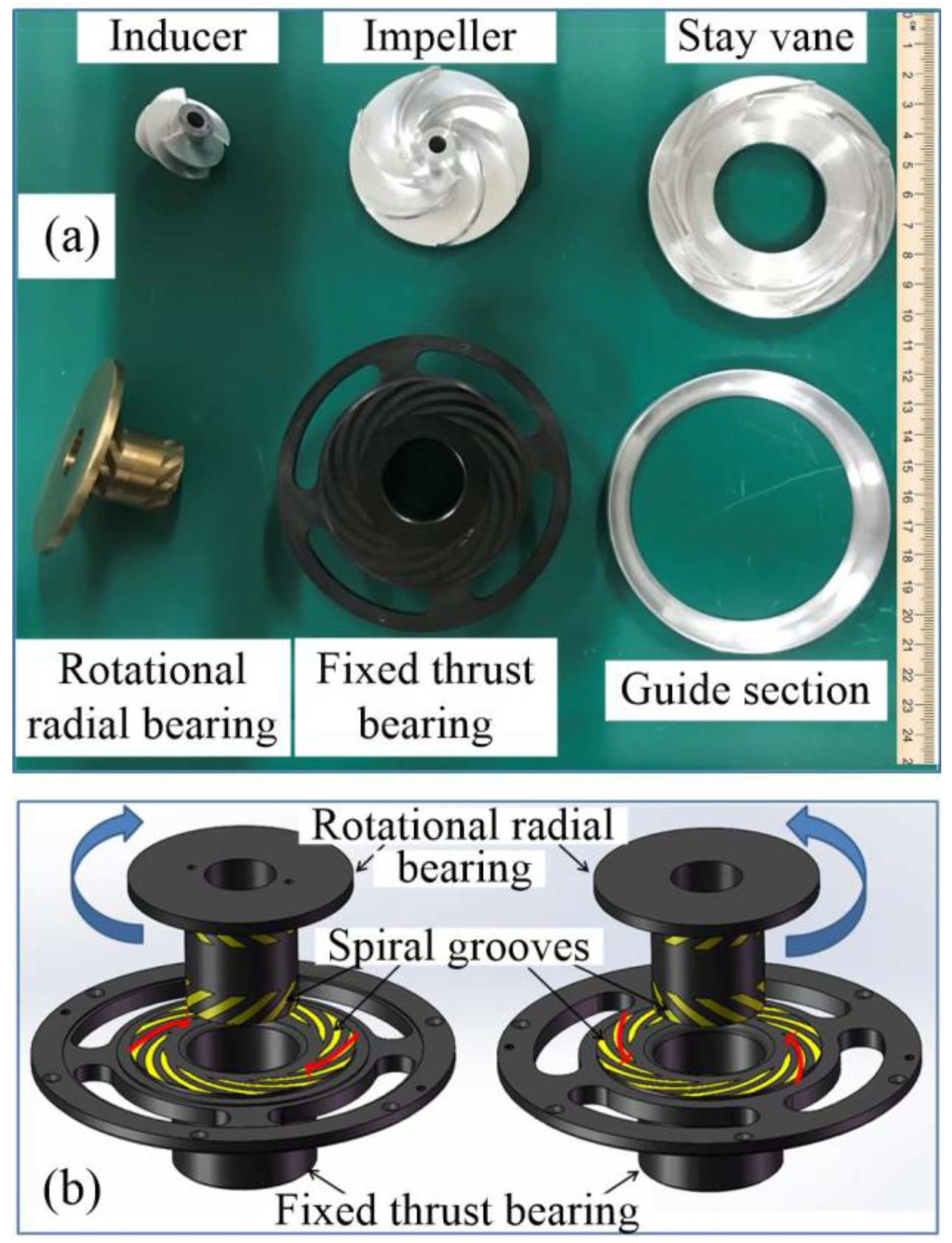
The main hydraulic components of the high-speed centrifugal pump are shown in Figure 2a. The hydrodynamic bearings are made up of the rotational radial ring and the fixed thrust ring as a pair, as shown in Figure 2b. Except for the opposite rotational direction of spiral grooves, two rings have the same parameters and distribute at the inlet and outlet, respectively. When rotational ring rotates, the working fluid is sucked into spiral grooves and is blocked by the dam region. The retention of the working fluid promotes a high-pressure zone to form. The pressure is applied on the stationary ring providing the bearing capacity for the rotor.
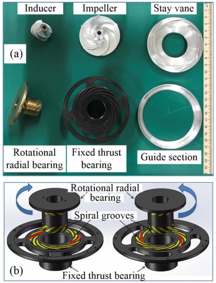
Figure 2.
(a) Main hydraulic components of high-speed centrifugal pump. (b) Details of Hydrodynamic Bearings.
Table 1 lists the main parameters of the high-speed centrifugal pump at the designed point. Due to the limitation of processing technology, the impeller is designed as a semi-open cylindrical structure by the velocity coefficient method. The meridian profiles use the Bezier curves, whereas the cross-sectional area has a uniform changing. In order to ensure a square throat, the stay vane is designed to be two-dimensional, twisted by the area ratio method. Profiles of the inlet section uses the circular arc curves; those of the diffusion and outlet sections adopt the Bezier curves. The vane inlet angle equals the outlet fluid flow angle. In addition, labyrinth seals are designed on the stay vane to reduce the leak at the back gear. The guide section is a circular flow channel with no vanes. The radial flow from the impeller outlet can be changed into an axial flow by the stay vane and the guide section. In order to ensure a uniform change of the flow area and a smoother flow, the guide section is made up of two curves.

Table 1.
Main parameters of high-speed centrifugal pump.
2.2. Meshing
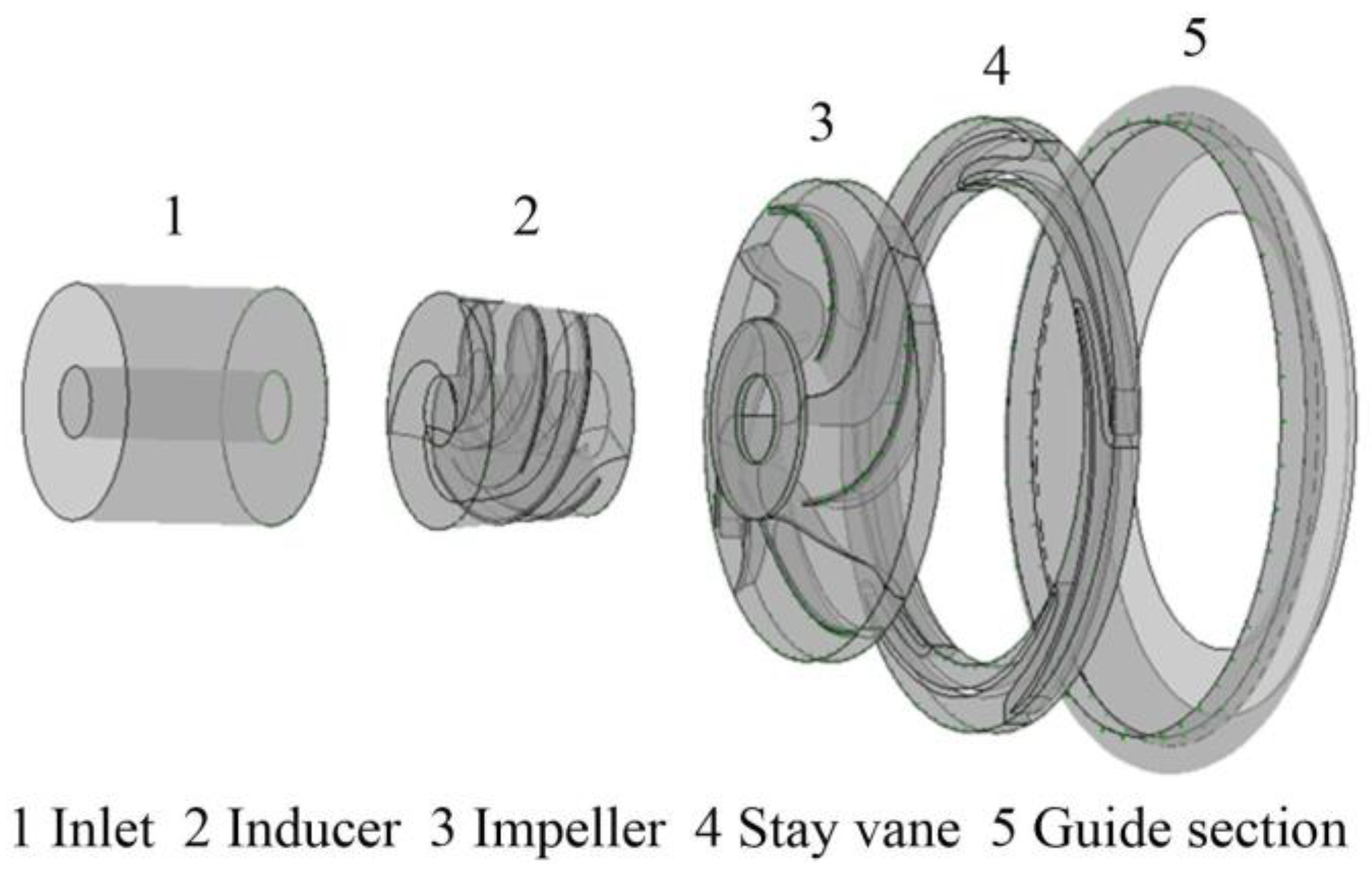
The flow-path shown in Figure 3 is divided into five regions: the inlet, the inducer, the impeller, the stay vane, and the guide section of the high-speed pump. The physical model of the high-speed pump is established by Solidworks 2018. The meshes near the vane surfaces, the flow path wall and the blade tip clearance are specifically refined.
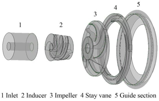
Figure 3.
Flow-path of high-speed pump.
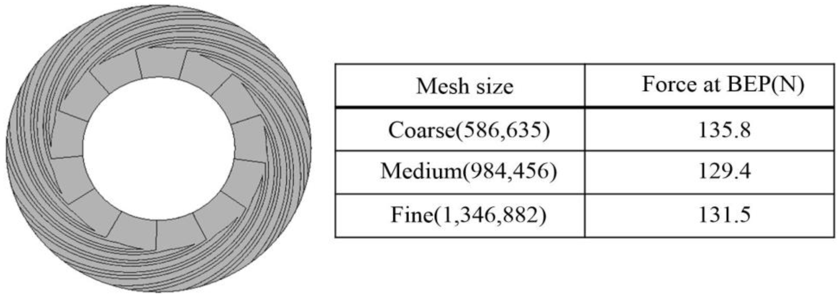
The mesh independence study was performed at the designed point with the mesh size of 2,087,663 (coarse), 4,569,430 (medium), and 6,857,792 (fine). The computed heads of different mesh sizes are listed in Table 2. The deviation between the coarse and the medium mesh size was 3.64%, whereas the deviation between the medium and the fine mesh size was 0.64%. Considering balancing the accuracy and computational cost, the medium mesh size was selected for the following study. The quality of the mesh was greater than 0.8 and all values of the distortion, the Jacobi, and the aspect ratio satisfied the calculating accuracy.
Table 2.
Mesh independence study. BEP: Best efficiency point.
Generally, the radial bearing has sufficient load capacity to balance the weight of the rotor itself. The load capacity from the thrust bearing is more critical for the high-speed operation of a hydrodynamic centrifugal pump. Thus, the thrust bearing needs to be given attention. The mesh of flow path in the thrust bearing and the mesh independence study are shown in Figure 4. The liquid film thickness was about 10–50 μm in the thrust bearing, which was far from the size of the flow path in the pump. Therefore, a separate numerical study is presented on the spiral groove thrust bearing for the evaluation of the load capacity. The non-slip boundary condition was applied. The outlet pressure of the pump was set as the inlet pressure of the bearing. The rotation speed was 7200 rpm.
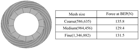
Figure 4.
Mesh of flow path in the thrust bearing and mesh independence study.
2.3. Control Equation and Solution
The commercial CFD code CFX (Computational Fluid X) 18.0 was employed to simulate the 3D incompressible flow under a steady condition. It was assumed that physical properties of the fluid kept constant during the computation, as well as the effect of gravity, was neglected. The continuity and momentum equations are shown below [22]:
Continuity equation:
Momentum equation:
where ρ is the liquid density, xi, xj is the components along three directions, i, j = 1, 2, 3. , is the velocity components, is the components of body force, is the reduced pressure including the turbulence kinetic energy and centrifugal force, and v is the coefficient of the kinematic viscosity.
Kim et al. [23] pointed out that the turbulence model is popular for numerical research of the centrifugal pump. They examined the applicability of the standard model, the renormalization group (RNG) model, and the Realizable model, concluding that these three models were suitable for the numerical simulation of the internal flow inside a centrifugal pump. Therefore, the standard model is chosen in this study and the transport equations are shown as follows. The detailed information is introduced in [23,24].
The standard turbulence transport equations:
The turbulent viscosity is computed as follows:
where , , , , and are the coefficients of the turbulence model. represents the generation of the turbulence kinetic energy induced by the mean velocity gradients. Pressure-velocity coupling is achieved by the SIMPLE algorithm, which can reformat the continuity equation and derive an additional condition for the pressure.
The inlet and outlet boundary conditions greatly affect the accuracy and the convergence of calculation results. The pressure inlet and mass flow rate outlet conditions were specified at the inlet and outlet to obtain good convergence. The turbulence kinetic energy and the turbulence dissipation rate of the inlet are computed by Equation (5).
where is the inlet velocity and is the inlet diameter.
As for the wall boundary condition, the no slip condition was imposed on the wall surface. This assumes that there is no relative velocity between the liquid and the wall. Therefore, the flow adjacent the wall had a low Reynolds number and the standard wall function was adopted to compute the flow at the adjacent region. If there is a point, P, and the distance from P to the wall is , the mean velocity of the fluid and the turbulence kinetic energy at the wall-adjacent cell centroid P is and . Then, the law-of-the-wall for mean velocity yields [24]:
where is the dimensionless velocity and . is the dimensionless distance from the wall and . and are empirical constants and the values are 0.4187 and 9.793, respectively.
The General Grid Interface (GGI) delivers the physical parameters between the rotating rotor interface and stator rotor interface. The rotational periodic boundary condition was set for the impeller and the stay vane to reduces the quantity of the mesh and improve the computational efficiency. Water was set as the working fluid.
3. Experimental Study
3.1. Test Rig
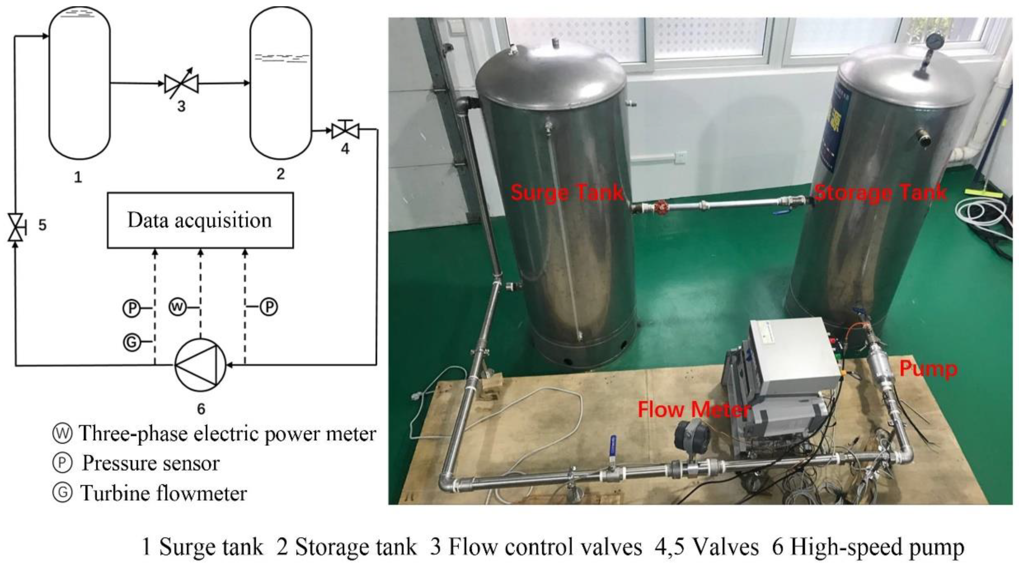
Based on the schematic diagram and the picture of the high-speed pump test rig displayed in Figure 5, the experimental test was performed on the prototype pump with six blades in the impeller and seven blades in the stay vane to verify the numerical results. The experimental system was a close cycle, in which water was driven by the pump and flows circularly between the surge tank and the storage tank.

Figure 5.
High-speed Pump Test Rig.
The hydrodynamic bearings lubricated by the system fluid were designed in the high-speed centrifugal pump. The rotational speed was adjusted by the frequency-converter. The surge tank was filled with water during operation to maintain the system stability and reduced the system fluctuation under varied test conditions. The liquid indicators on the surge tank and storage tank were used to observe and adjust the liquid level of two tanks. The experimental system was driven by the PC-16RH DC power supply. The noise of the pump was measured in a noise laboratory.
A turbine flowmeter (SIN-LWGY-DN32) was adopted, which is a kind of velocity flow meter. The blades inside it transferred the fluid velocity into its rotational speed. Then the rotational speed proportional to the flowrate was converted to electrical signals. The measuring range was 0.8–15 m3·h–1 and the measurement accuracy was ±1.0%. The pressure transmitter (CYYZ11, measuring range: 0–1.5 MPa, accuracy: ±0.25%) applied in this study was a diffused-silicon sensor. It converted the pressure of the measured gas or liquid into an output electrical signal. The three-phase digital power meter converted different electrical signals, such as the voltage, current, frequency, power, and power factor into digital signals and display them. The measuring range is 0–2000 W with an accuracy of ±0.5%.
3.2. Experimental Results
Table 3 lists the experimental results of the high-speed pump at 7500 rpm. The hydrodynamic head of the high-speed pump reached 24.78 m and that of the whole system reached 23.31 m under the designed flow rate Q = 4.0 m3·h−1. The efficiency of the hydraulic components was 31.13% and total efficiency was 29.29%. The head loss was 1.47 m in the flow channel of the motor, while the efficiency loss was 1.84%. At the best efficiency point, the maximum flow rate is 5.63 m3·h−1 and the highest head was about 32 m. When the flow rate decreased, the heads of both the whole system and the hydraulic components increased, and the total input power decreased. The efficiencies of the hydraulic components and the whole system increased to maximum values first and then kept reducing with the decrease of the flow rate. The efficiency loss in the flow channel of the motor decreased with the flow rate. Compared with pumps employing ball bearings, the noise of the high-speed pump in the current work distributed more uniformly in four directions. Here, the average noise was 53.89 dB, which was much smaller.
Table 3.
Experimental results of high-speed pump at 7500 rpm.
The experimental results verify the feasibility of the water-lubricated bearing in the small-sized high-speed centrifugal pump as supporting structures and the effectiveness to improve the lifetime and vibration noise of the hard-supporting structures.
4. Results and Discussion
4.1. Validation of Numerical Model
The computational head and efficiency are compared with the experimental results; Figure 6 presents a good agreement between them. At the designed point, the deviation between the predicted head of 25.18 m and the experimental head of 25.13 m was 0.2%; the deviation between the predicted efficiency of 29.4% and the experimental efficiency of 28.9% was 1.7%. The numerical efficiency was larger than the measured efficiency, although their patterns agreed with each other. This is because the leak at the back gear was neglected in the numerical study. Generally, the computational model qualified for predicting the performance of the high-speed pump.
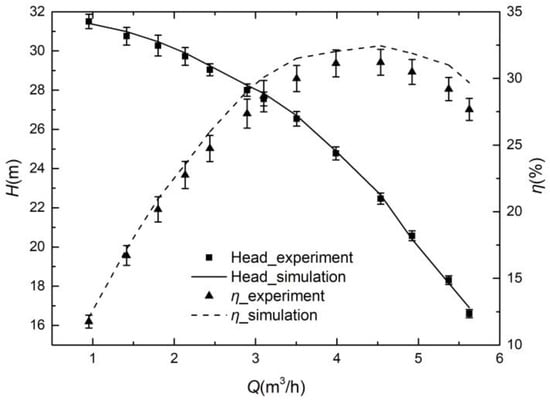
Figure 6.
Comparison between computed and measured head and efficiency.
In order to optimize the hydrodynamic performance of the high-speed centrifugal pump, the blade number of the impeller and stay vane was varied. We fixed the basic parameters of the impeller, the vane inlet angle, and inner and outer diameters. The blade number of the impeller was changed from 4 to 8; that of the stay vane was changed from 3 to 14. Then, 60 combinations were established and numerically investigated. The influence of the matching relation between different impellers and stay vanes on the hydrodynamic performance of the high-speed centrifugal pump was herein investigated.
4.2. Effect of Hydrodynamic Bearings
The pressure distribution at the thrust surface of the dynamic pressure bearing is displayed in Figure 7a. The area marked by black lines is the position of a single spiral groove. When the bearing rotated at a high speed, a low-pressure area formed at the inlet and drew the working fluid into spiral grooves. The retention and squeeze of the working fluid by the dam region promoted a high-pressure zone to form. The load capacity was achieved depending on the pressure difference. Figure 7b indicates that the bearing capacity decreased rapidly with the increase of the liquid film thickness. When the liquid film thickness was greater than 30 μm, a further increase of the thickness slightly affected the bearing capacity. The thrust bearing supplied up to a 650 N load capacity with a 10 μm fluid film thickness at 7200 rpm. Since the axial force for the pump structure was no more than 200 N, a 15 μm fluid film at 7200 rpm satisfied the requirement. The flow rate through the dynamic pressure bearing was between 10−5 and 10−4 kg·h−3. Four orders of the magnitude difference between it and the mainstream slightly influenced the head loss.
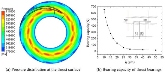
Figure 7.
(a) Pressure distribution at the thrust surface and (b) bearing capacity of thrust hydrodynamic bearings under different film thickness at 7200 rpm.
4.3. Effect of Blade Number of Impeller
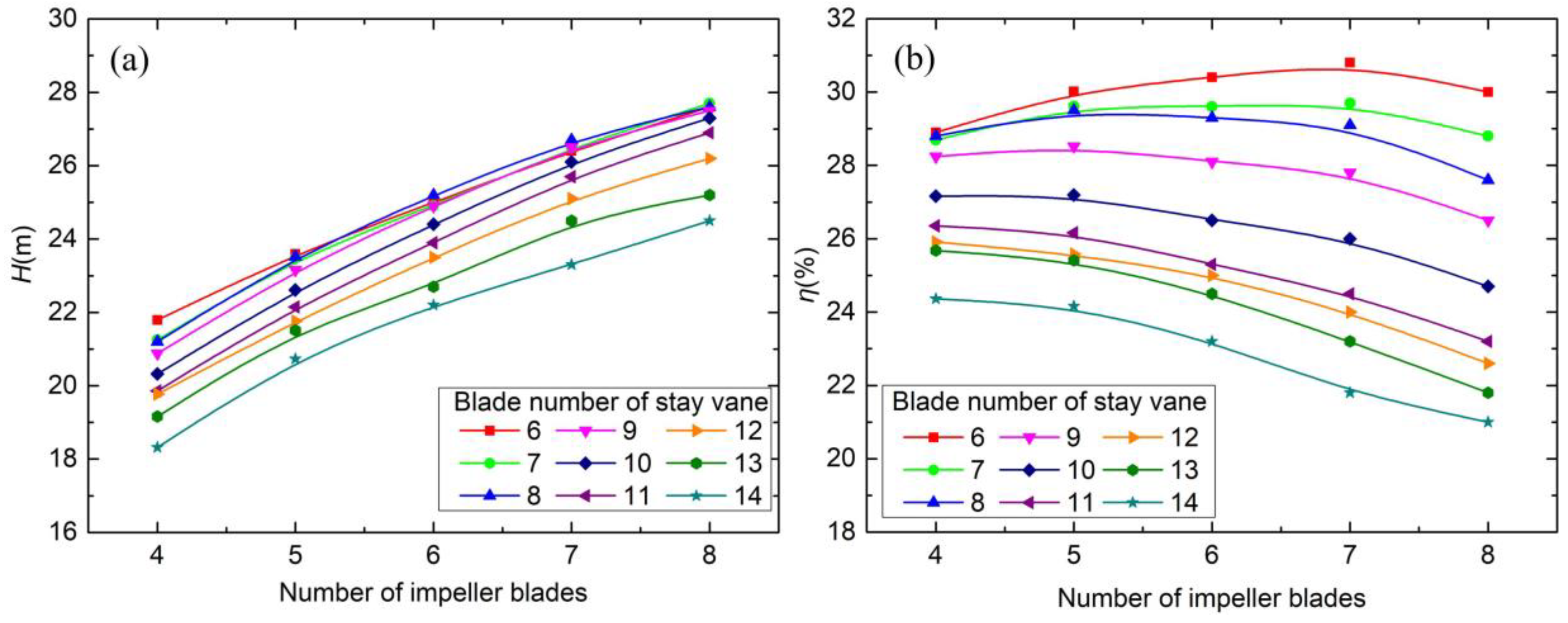
The head and efficiency of the high-speed pump under different blade number of the impeller are plotted in Figure 8. From Figure 8a, it can be observed that an increase in the blade number of the impeller resulted in an increase of the head with a gradually reduced growth rate. The theoretical head was proportional to the slip factor. According to Equation (7), when increasing the blade number, the increased slip factor led to an increase of the head. Because the derivative of the head with respect to the blade number showed a decreasing trend, the increase of the head gradually reduces.
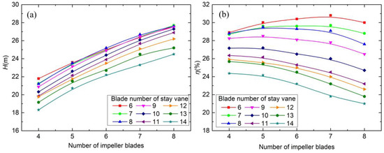
Figure 8.
(a) Head and (b) efficiency under a different number of impeller blades.
Pfleiderer slip factor:
where P is a correction factor and . D1 and D2 is the inlet radius of the outlet radius of the stay vane. Z is the number of blades. is the excretion coefficient and . is the outlet angle of the blade. a is an empirical coefficient related to the pump structure.
Darcy-weisbach Equation [25]:
where is the head loss. L and D are the length and the inner diameter of the pipe. v is the fluid velocity. g is the gravity acceleration. f is the friction factor, which is related to the fluid viscosity, Reynolds and the relative roughness of pipe wall.
The efficiency of the high-speed pump increased to a maximum value first and then kept reducing under the increased blade number of the impeller, as shown in Figure 8b. The increased blade number of the stay vane decreased the flow area and increased the flow velocity under a given flowrate. The head loss was proportional to the square of flow velocity according to the Darcy-weisbach equation, as shown in Equation (8). The increment of the head was a result of the increased blade number and could not counteract the increased head loss. Thus, the efficiency showed a decreasing trend. In addition, the increased blade number caused more hydrodynamic loss and reduced efficiency. It can also be observed from the figure that the point with the highest efficiency kept moving toward the bottom left as the blade number increased.
4.4. Effect of Blade Number of Stay Vane
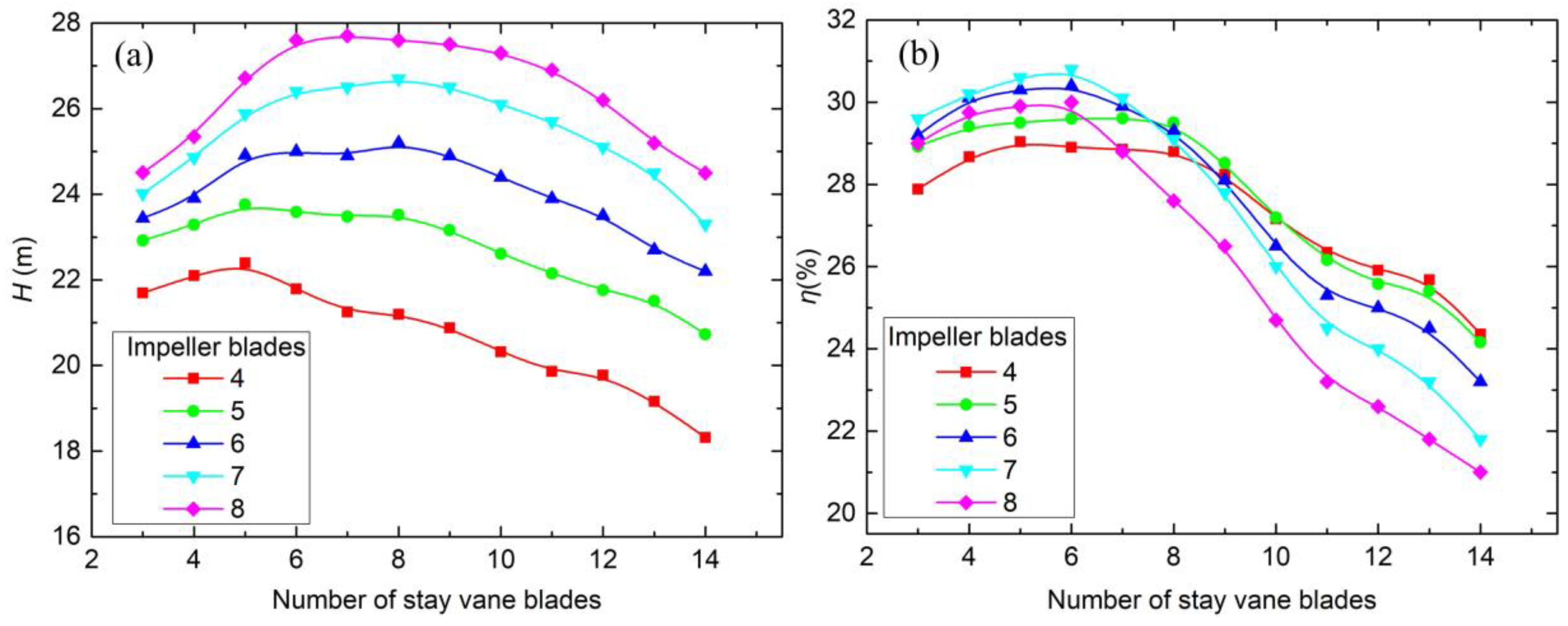
Figure 9 displays the head and efficiency under different blade number of the stay vane. Both the head and the efficiency increased first and then decreased when the blade number increased. The theoretical head equation was obtained based on the area ratio principle:
where Y is the ratio of the impeller outlet area and the throat area of the stay vane.
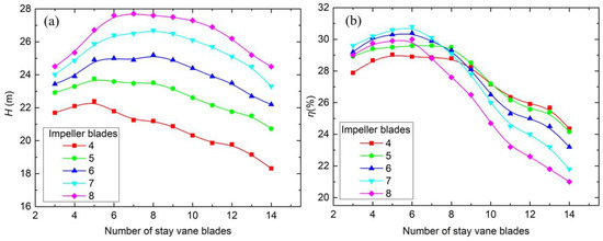
Figure 9.
(a) Head and (b) efficiency under a different number of stay vane blades.
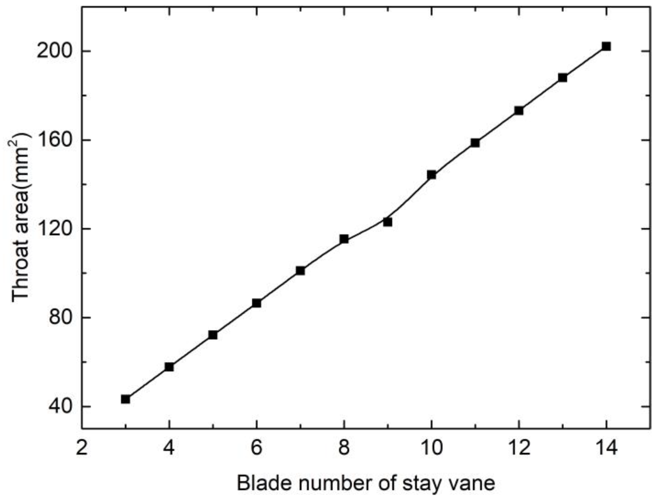
The throat area is the inlet of the diffuser section, which has the smallest flow area. The size of the throat area greatly affects the pump performance. The increasing trend of the throat area with the blade number is shown in Figure 10, which results in a smaller area ratio, the reduced flow velocity through the throat, and ultimately the decreased head. Oppositely, when the blade number of the stay vane is very small, there is a mismatching between the impeller and the stay vane. The backflow and secondary flow generated in the circular flow path at the rear of the stay vane reduce the head and efficiency of the whole pump.
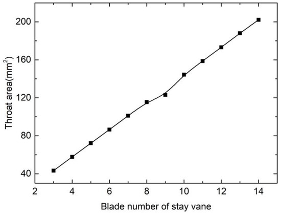
Figure 10.
Throat area under a different number of stay vane blades.
Among all computational cases, the minimum head and maximum head were 18.5 m and 27.9 m, while the lowest and the highest efficiency were 20.8% and 30.8%. The differences between the highest and lowest values of the head and the efficiency were 9.4 m and 10.0%, respectively. It was clear that the matching relation between the impeller and the stay vane was crucial to the pump performance.
4.5. Characteristic of Internal Flow Field
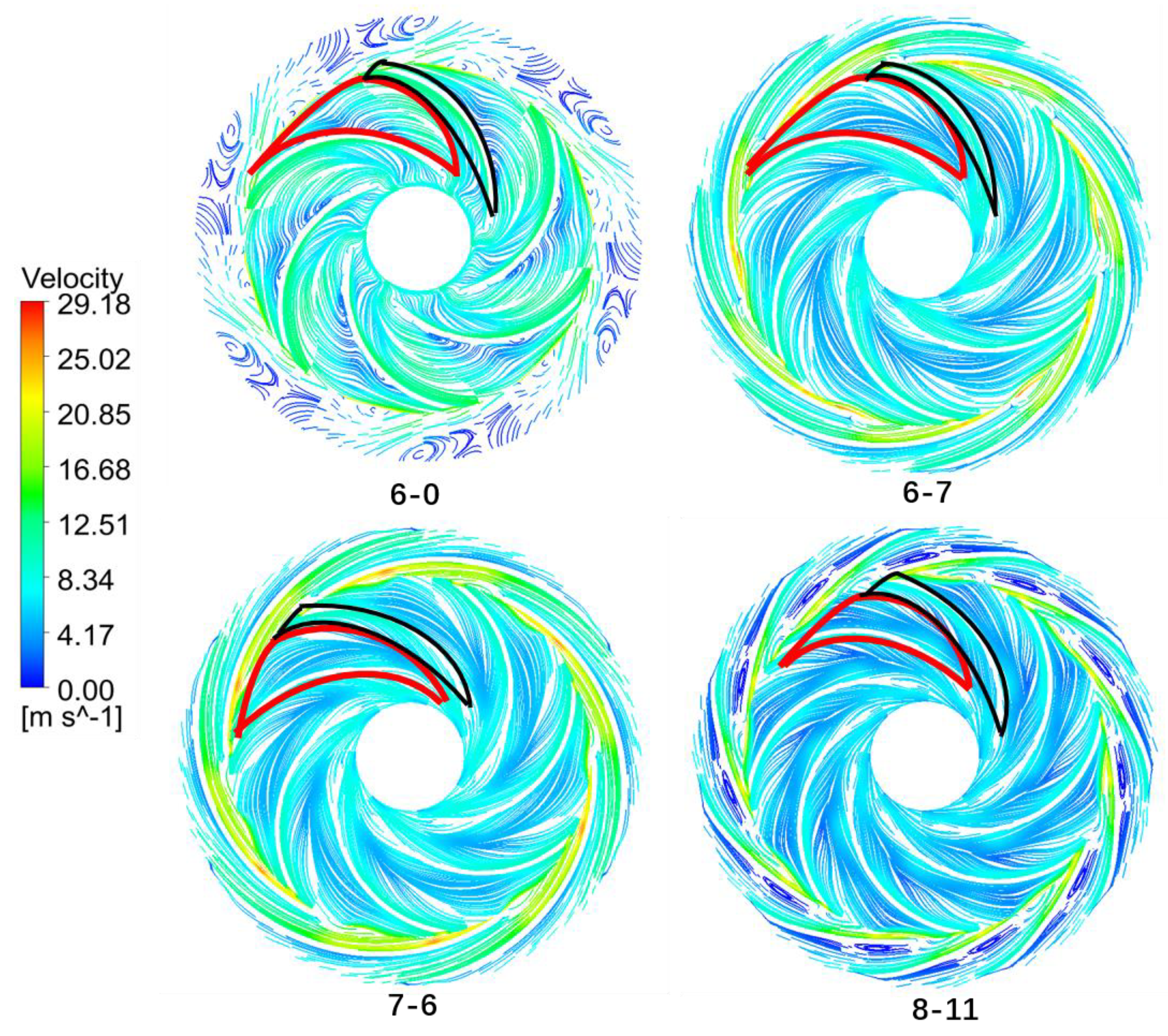
The internal flow fields were studied under four representative cases listed in Table 4. The computational cases are the combinations of different blade number in the impeller and the stay vane. The case with the seven-blade impeller and the six-blade stay vane had the highest efficiency. Case 6-7 was the prototype in the experiment. Case 6-0 with no blades in the stay vane was an extreme case. Case 8-11 was another extreme case with more blades in the impeller and the stay vane.
Table 4.
Computational cases of different combinations of impeller and stay vane.
4.5.1. Velocity Streamline under Different Cases
The velocity streamlines of the high-speed pump under four computational cases are displayed in Figure 11. The field remarked in red is the wake area; the black is the jet flow region. With the increase of the blade number in the impeller, the proportion of the wake area in the whole region of a single flow path decreased, while the jet flow region almost kept constant. Hence, the proportion of the jet flow region increased with the blade number, which led to an increased head. From the velocity streamlines under Case 6-0 with no blades in the stay vane, it can be observed that the streamlines are continuous only at the outlet of the impeller jet area. A great number of vortexes are generated in other regions due to the mixture of the jet flow and wake flow, which resulted in a sharp decline of the head and efficiency. Therefore, a stay vane at the impeller outlet was indispensable in a high-speed centrifugal pump.
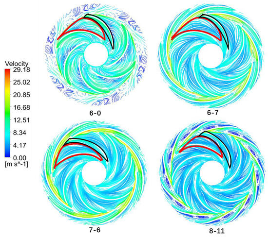
Figure 11.
Velocity streamline of high-speed pump under four computational cases.
Figure 12 shows the enlarged velocity streamlines on the stay vane. Different degrees of the secondary flow exist at the diffuser of the stay vane under different computational cases. The regions of the secondary flow and vortex flow were larger under Case 8-11. This phenomenon reduced the efficiency to 23.3%.
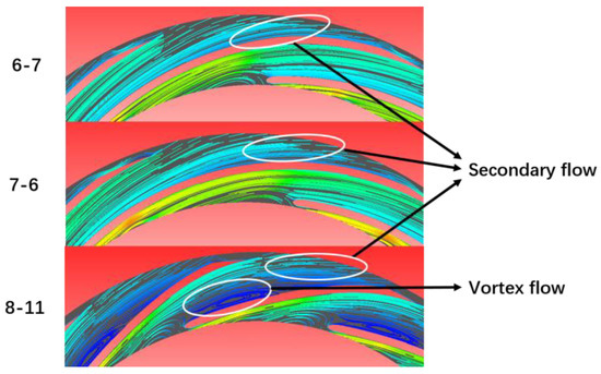
Figure 12.
Enlarged velocity streamline on stay vane.
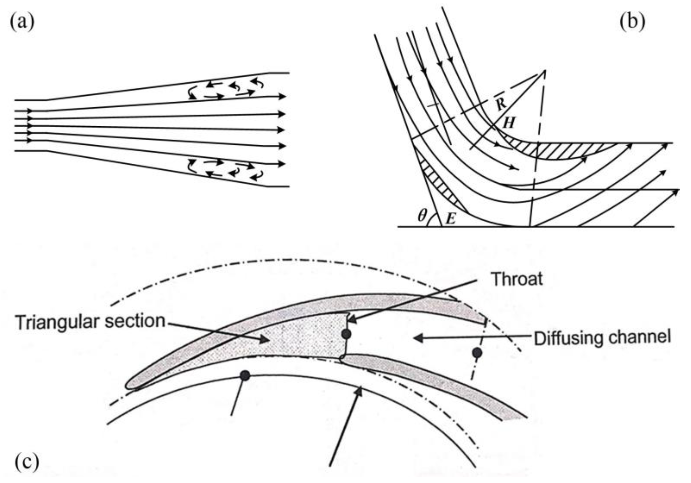
The diffusing channel of the stay vane is shown in Figure 13c, which has a gradually enlarged cross-sectional area and a curved flow path. Moreover, the throat area is specified in Figure 13c. The vortex was generated in a diffuser flow, as shown in Figure 13a. The curved duct flow occurred in a curved path, as shown in Figure 13b, which resulted in the secondary flow and flow separation. Therefore, the fluid flow in the diffusing channel of the stay vane was a superposition of the diffuser flow and the curved duct flow. The drag coefficient increased with the divergence angle. A sufficient length of the diffusion in the stay vane must be guaranteed to decrease the divergence angle and then increase the efficiency. The curved duct flow in Figure 13b resulted in the secondary flow and the flow separation at the diffusion outlet in the stay vane. The corner of the stay vane was theoretically smaller and the caliber and radius of curvature were larger in Case 8-11. The flow loss in the curved duct was supposed to be smaller, however the appearance of the vortex at the diffuser upstream of the stay vane aggravated the turbulence.
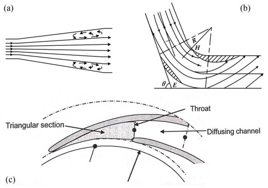
Figure 13.
(a) Diffusion flow, (b) curved duct flow, and (c) diffusing channel of stay vane [26].
4.5.2. Static Pressure Distribution under Different Cases
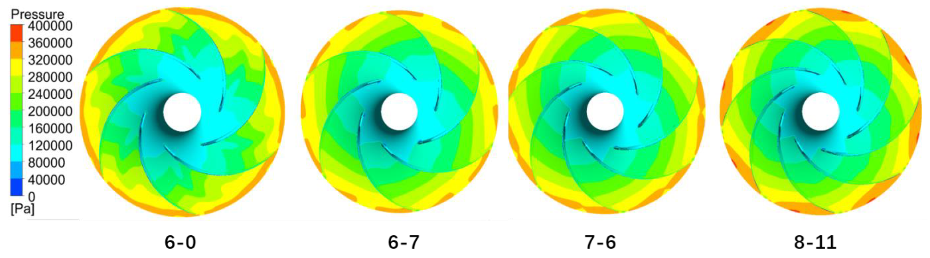
The static pressure distributions of high-speed pumps under four computational cases are presented in Figure 14. There was a clear gradient of pressure distributions in the flow path of the impeller. The low-pressure area focused on the leading edge of the blades. The flow area decreased when the number of impeller blades increased. Because of the enhanced restriction on the flow, it was harder to form the backflow in the flow path. The pressure at the outlet grew higher and higher. It was clearly visible that the pressure gradient distributed nonuniformly under Case 6-0 with no stay vane, especially when comparing with Case 6-7. Further, a lower pressure area was found in the middle of the flow path, given the pressure in the two sides. The comparison of Figure 11 and Figure 14 indicates that the appeared vortex significantly decreased the head and efficiency of the high-speed centrifugal pump.

Figure 14.
Static pressure distribution of high-speed pump under four computational cases.
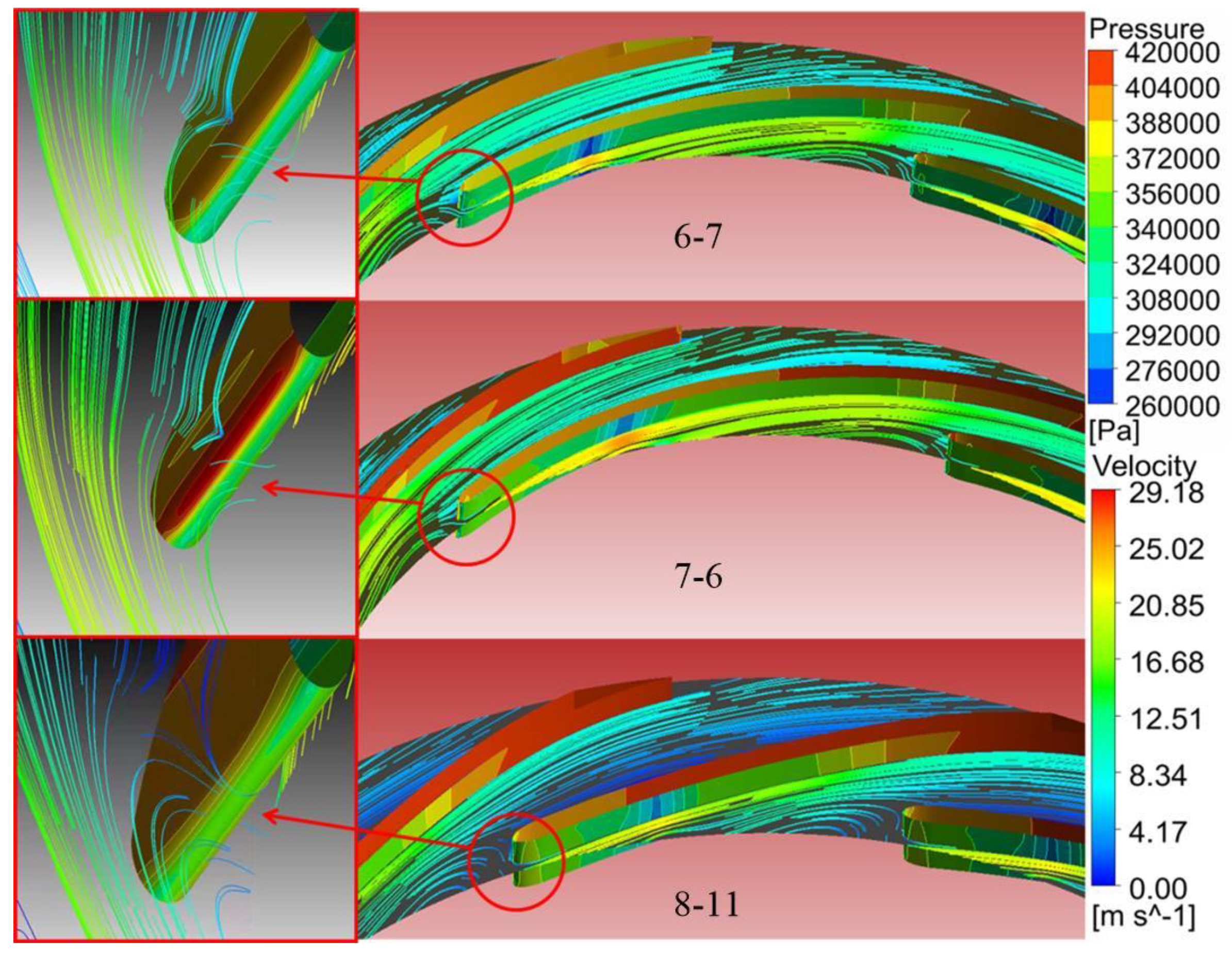
The static pressure distributions and velocity streamlines on the stay vane under different computational cases are shown in Figure 15. The fluid pressure decreased first and then increased when flowing on the suction surface of the stay vane. Accordingly, the velocity followed the trend of pressure. It led to the appearance of low-pressure near the midpoint of the stay vane inlet. The flow was squeezed by the blades and the vortex was inevitably generated on the pressure surface of the stay vane inlet. There was a high-pressure area at the blade when the vortex appeared. The pressure on the leading edge of the blade increased rapidly to the high-pressure area and then decreased. It gradually increased when the fluid flowed into the diffusion section. Comparing the numerical results under the three cases, the vortex area, being proportional to the blade number of the stay vane, was the largest for Case 8-11. The structure of Case 7-6 had a smaller vortex area and then a higher efficiency than Case 6-7.
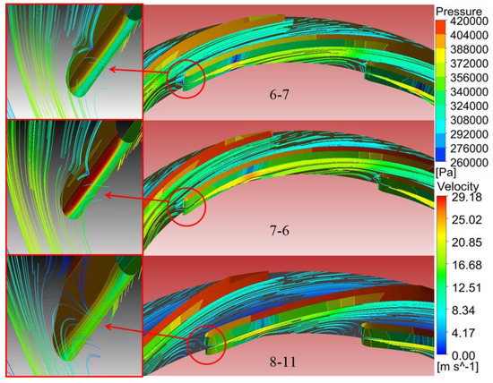
Figure 15.
Static pressure distribution and velocity streamline on stay vane under different computational cases.
5. Conclusions
In this study, we proposed a three-dimensional numerical model for a novel high-speed centrifugal pump with hydrodynamic liquid lubricated bearings. The feasibility of the model was proven by experimental data in hydraulic tests. Moreover, the matching performance between the impeller and the stay vane was analyzed. The following conclusions are drawn from this study:
- The hydrodynamic bearings can well support the high-speed operation of the centrifugal pump. The balance of the axial force and the bearing capacity during the operation can lead to the axial displacement of the impeller, which is less than 15 μm. The change of the head caused by the axial displacement is within 0.39 m.
- A larger number of impeller blades leads to an increase in the head with a decreasing amplitude. In addition, it has a favorable effect on the efficiency of the high-speed pump first and then decreases the efficiency gradually.
- The increase first and then the decrease of the head and the efficiency are controlled by increasing the stay vane blade number.
- The head and efficiency can reach 26.3 m and 30.8% when the impeller and the stay vane are perfectly matched. The blade number has a significant impact on the performance of the high-speed centrifugal pump.
Author Contributions
Investigation, R.X.; data curation and paper writing, R.X. and Y.C.; experiment system design, L.C.; experimental apparatus build-up, X.Z. and X.F.; supervision and project administration, Y.H. All authors contributed equally in this paper.
Funding
This research is funded by the Youth Innovation Team of Shaanxi Universities, the Key Research and Development Plan of Shaanxi Province (2018ZDXM-GY-057), and China Postdoctoral Science Foundation (2018M640983).
Conflicts of Interest
The authors declare no conflict of interest. The founding sponsors had no role in the design of the study; in the collection, analyses, or interpretation of data; in the writing of the manuscript, and in the decision to publish the results.
Nomenclatures
| ρ/kg·m−3 | Density | D/mm | Diameter |
| P/bar | Pressure | / | Blade angle |
| n/rpm | Rotational speed | Q/m3·h−1 | Flow rate |
| H/m | Head | W/W | Power |
| b/mm | Passage width | g/m·s−2 | Gravity |
| Z/(-) | Number of blades | v/m·s−1 | Velocity magnitude |
| k/m2·s−2 | Turbulent kinetic energy | f/(-) | Friction factor |
| rpm/(-) | Revolution per minute | ψ/(-) | Excretion coefficient |
| /(-) | Slip coefficient | Y | Area ratio |
| h(μm) | Liquid film thickness | ||
| Subscription | |||
| 1 | Impeller Inlet | 2 | Impeller Outlet |
| 3 | Stay vane inlet | 4 | Stay vane outlet |
| hyd | Hydraulic components | t | Total |
| thr | Throat | dif | Diffuser |
References
- Nemdili, A.; Hellmann, D.H. The requirements to successful centrifugal pump application for desalination and power plant processes. Desalination 1999, 126, 199–205. [Google Scholar] [CrossRef]
- Cirino, M.; Friedrich, K.; Pipes R, B. The effect of fiber orientation on the abrasive wear behavior of polymer composite materials. Wear 1988, 121, 127–141. [Google Scholar] [CrossRef]
- Nair, V.P.S.; Nair, K.P. Finite element analysis of elastohydrodynamic circular journal bearing with micropolar lubricants. Finite Elem. Anal. Des. 2004, 41, 75–89. [Google Scholar] [CrossRef]
- Kumar, V.; Sharma, S.C.; Jain, S.C. On the restrictor design parameter of hybrid journal bearing for optimum rotordynamic coefficients. Tribol. Int. 2006, 39, 356–368. [Google Scholar] [CrossRef]
- Prehn, H.; Friedrich, F. Sliding wear performance of polymer composites under abrasive and water lubricated conditions for pump applications. Wear 2005, 259, 693–696. [Google Scholar] [CrossRef]
- Litwin, W. Influence of surface roughness topography on properties of water-lubricated polymer bearings: Experimental research. Tribol. Trans. 2011, 54, 351–361. [Google Scholar] [CrossRef]
- Gerasimov, V.S.; Nikiforov, S.A.; Pautov, Y.M.; Snetkov, V.G.; Fedorov, G.P.; Mikhailov, A.D. Development of high-load water-lubricated radial-axial bearings for electric-pump units in the first loop of a nuclear power plant. At. Energy 2000, 89, 1027–1030. [Google Scholar] [CrossRef]
- Nakata, K. Rubber bearing apply for pumps. Pump Inf. 1980, 1, 28–32. [Google Scholar]
- Memardezfouli, M.; Nourbakhsh, A. Experimental investigation of slip factors in centrifugal pumps. Exp. Therm. Fluid Sci. 2009, 33, 938–945. [Google Scholar] [CrossRef]
- Andenson, H. The area ration system. World Pump. 1984, 6, 34–38. [Google Scholar]
- Iqbal, M.; Wasy, A.; Batani, D.; Rashid, H.; Lodhi, M.A.K. Design modification in rotor blade of turbo molecular pump. Nucl. Inst. Methods Phys. Res. A 2012, 678, 88–90. [Google Scholar] [CrossRef]
- Curtis, E.M.; Hodson, H.P.; Banieghbal, M.R.; Denton, J.D.; Howell, R.J.; Harvey, N.W. Development of blade profiles for low-pressure turbine applications. J. Turbomach. 1997, 119, 531. [Google Scholar] [CrossRef]
- Muggli, F.A.; Holbein, P.; Dupont, P. CFD calculation of a mixed flow pump characteristic from shutoff to maximum flow. J. Fluids Eng. 2002, 124, 132–141. [Google Scholar] [CrossRef]
- Sriveerakul, T.; Aphornratana, S.; Chunnanond, K. Performance prediction of steam ejector using computational fluid dynamics: Part 1. Validation of the CFD results. Int. J. Therm. Sci. 2007, 46, 812–822. [Google Scholar] [CrossRef]
- Hornsby, C. CFD—Driving pump design forward. World Pumps 2002, 431, 18–22. [Google Scholar] [CrossRef]
- Jeon, Y.; Choi, J.; Cho, K.; Kim, S. Characteristics of tunnel fires. Concr. Struct. 2011, 6, 95–124. [Google Scholar]
- Kim, S.; Choi, Y.; Lee, K. Design optimization of mixed-flow pump impellers and diffusers in a fixed meridional shape. AIP Conf. 2010. [Google Scholar]
- Singh, P.; Nestmann, F. Experimental investigation of the influence of blade height and blade number on the performance of low head axial flow turbines. Renew. Energy 2011, 36, 272–281. [Google Scholar] [CrossRef]
- Knierim, C.; Baumgarten, S.; Fritz, J. Design process for an advanced reactor coolant pump for a 1400 MW nuclear power plant. In Proceedings of the FEDSM2005:2005ASME Fluids Engineering Divisions Summer Meeting and Exhibition, Houston, TX, USA, 19–23 June 2005. [Google Scholar]
- Chakrabort, S.; Choudhuri, K.; Dutta, P. Performance prediction of centrifugal pumps with variations of blade number. J. Sci. Ind. Res. 2013, 72, 378. [Google Scholar]
- Krain, H. Experimental observation of the flow in impellers and diffusers. In Von Karman Inst for Fluid Dyn Flow in Centrifugal Compressors; von Karman Institute for Fluid Dynamics: Saint-Genesius-Rode, Belgium, 1984. [Google Scholar]
- Jafarzadeh, B.; Hajari, A.; Alishahi, M.M. The flow simulation of a low-specific-speed high-speed centrifugal pump. Appl. Math. Model. 2011, 35, 242–249. [Google Scholar] [CrossRef]
- Li, X.H.; Zhang, S.J.; Zhu, B.L.; Hu, Q.B. The study of the κ-ε turbulence model for numerical simulation of centrifugal pump. Int. Conf. Comput. Aided Ind. Des. Concept. Des. 2006, 1–5. [Google Scholar]
- ANSYS Fluent Theory Guide; ANSYS Inc.: Canonsburg, PA, USA, 2015.
- Christos, B.; George, T. Accurate explicit equations for the determination of pipe diameters. Int. J. Hydraul. Eng. 2013, 2, 115–120. [Google Scholar]
- Gülich, J.F. Centrifugal Pumps; Springer: Berlin/Heidelberg, Germany, 2010. [Google Scholar]


© 2019 by the authors. Licensee MDPI, Basel, Switzerland. This article is an open access article distributed under the terms and conditions of the Creative Commons Attribution (CC BY) license (http://creativecommons.org/licenses/by/4.0/).