1. Introduction
Newly constructed low-energy buildings are characterised by their ability to balance heat gain and heat loss. This follows recent improvements in the thermal insulation of interior partitions and the introduction of solutions that allow for the recovery of heat from ventilated air [
1,
2]. Heat gains, which are characterised by periodicity, allow not only for the temporary compensation of losses, but can also cause an increase in the air temperature in the building’s interior. Limiting the overheating effect in rooms and increasing the efficiency of utilising the heat gains can be achieved by a significant increase in the building’s thermal mass. It is well known that thermal mass has an effect on the building time constant [
3], the time lag and the decrement factor [
4,
5], and finally, on the thermal stability [
6] or thermal comfort of users [
7]. All these factors are particularly important in the context of the prevention of overheating across climate and building use [
8]. A building with an increased amount of thermal mass is able to time-shift and flatten out heat flow fluctuations [
9,
10]; this is referred to as the thermal inertia of a building [
8]. Guglielmini et al. [
11] introduce the term “passive thermoregulation effect” to describe the effect with which a building’s thermal inertia is able to reduce the fluctuations of the inside air temperature.
The traditional method of increasing thermal inertia is the use of high heat density construction materials or the application of phase change materials (PCM) within the building’s internal partitions. However, according to Reilly and Kinnane [
12], while high thermal mass structures are likely to be effective in hot climates, in cold climates the drawbacks of high thermal mass outweigh the advantages and high thermal mass leads to an increase in energy use. These conclusions were formulated for well insulated external walls during negative heat flux at night, considering any internal partition (or other internal accumulated volume) in which the heat was stored and released to the indoor environment without external loses. The other case for internal and external heavy mass partition was considered by Karlsson et al. [
13] and was tested in a cold climate. The results showed that passive energy storage through high thermal mass can significantly change the power consumption pattern, which can have significant benefits while having little influence on the total energy consumption, in most cases. Moreover, Jędrzejuk proved that in buildings with lower thermal insulation standards, the internal thermal capacity has a smaller influence on energy performance than in the case of very well insulated buildings [
14]. As shown in a paper written by Sun et al. [
15] and Corrado and Paduos [
16], thermal storage systems should be properly optimised and designed. In [
17], the authors revealed that high thermal storage walls with variable emission and absorption coatings are able to reduce the heating energy demand by 5%.
One of the methods of achieving effective heat storage is utilising phase change materials [
18]. Most of the research has been dedicated to modifying internal construction elements [
19,
20], for example, gypsum wall covering [
21,
22], furniture [
23], or ventilated slabs [
24]. The work presented by Zalba et al. [
25], has shown that it is possible to integrate PCM with the building’s elements, along with utilizing them in different types of storage tanks [
26]. Such solutions are usually installed in technical areas and not living spaces, and can be connected to Heating, Ventilation, Air Conditioning (HVAC) systems [
27]. Enclosing PCM in a container outside of living areas eliminates problems associated with toxicity and inflammability [
28]. Issues concerning the choice of material and the construction of the latent heat thermal energy storage systems (LHTESS) have already been described, e.g., in [
29]. Although PCM storage tanks are well described for water storage tanks for heating or hot water systems [
30,
31] as well as heat pumps [
32], their integration with a ventilation unit has still not been adequately studied. The latest reports show that the heat can be effectively transferred through ventilated air and storage in the PCM activated concrete blocks [
33]. It was proved that the ventilated tubes play the role of a regulator to unload the system, and thus heat the injected air. The main disadvantages of this solution is the total volume of the elements required for full scale building application, and construction problems. The system proposed and described in that paper does not suffer from the drawback mentioned above because it is more compatible with much higher density of thermal mass in the form of storage tank.
On the basis of the literature review it is possible to answer the question of whether heat gains should be stored within a building’s internal structure, including interior partitions, or in isolated, peripheral heat tanks. The goal of the analyses presented below was to investigate the potential of storing heat gains during the winter season. The solution proposed is a peripheral heat storage tank, which is located outside the thermal boundary of building. The amount of energy stored in a day, the energy capacity of the tank and the speed of charging and discharge were taken into consideration. The analysis was conducted using an energy efficient single-family building based on real physical parameters—inside temperature and instantaneous heat gains. Excess heat gains (EHG) were assumed and served as the basis for the temporary (TEHG), seasonal (SEHG) and average values.
2. Heat Flows in Low-Energy Buildings
The energy balance between heat gains (solar and internal) and heat losses in highly energy efficient or passive buildings is close to zero. During most of the heating or winter season, heat gains exceed losses and are not effectively used in the energy balance of the building. This period shows a significant increase in internal air temperature. This is particularly visible in buildings with low thermal mass, e.g., a lightweight timber frame construction. In this case, storing the excess heat is a highly reasonable means of increasing the gain utilization factor.
The authors propose a novel parameter called temporary excess heat gain. This excess refers to the thermal zone (room, group of rooms or the whole building). Its value is defined as follows:
where:
cp—heat capacity of air (kJ/kgK);
ρp—air density (kg/m3);
V—air volume exchange between the zone and storage tank (m3/h);
Δt—period of time during heat is exchange (h);
ΔT—temperature difference (K) given by the following formula:
Ti—current temperature in the building’s thermal zone (K);
Tr—reference temperature (K);
if Ti > Ts then Tr = Ts
if Ti ≤ Ts then Tr = Ti−1
where:
Ts—current temperature of storage medium,
Ti−1—previous air temperature in the building’s thermal zone (K);
In this article, the value of TEHG was set on the basis of real measurement data collected over 1 year for a single-family, ultra-low-energy, residential building. The value was defined using real, measurements of internal air temperature. For the same building, the LHTESS was proposed and analysed, both experimentally and numerically for two different building constructions, light and heavyweight.
The innovative heat recovery system proposed maintains a constant air temperature in the building’s thermal zone. A description of the heat storage tank can be found in
Section 4 of this article. The amount of heat stored in the tank was calculated according to the following assumptions. A 100% heat storage efficiency was assumed, along with the size of the tank, and allowing for an airflow in the room of up to 3 air changes per hour (420 m
3/h). Although these values are simplified, the aim of this article was not to find the heat storage potential of the tank, but rather, the potential excess heat gain in the building. Optimising the storage tank and the means of heat exchange between the airflow and the PCM closed in tubes could be a basis for further research. Due to the character of internal air temperature changes and the volume of the storage material, the amount of stored heat was limited. The results of the storage tank’s temporary charge can be found in
Section 5 of the article. Moreover, the amount of the seasonal heat gain available for storage and the reuse in the building was defined.
3. Application in an Existing Building
The case studied in this paper is a single-family residential building built in 2015. The building is located in the village of Zielonki Wies near Warsaw in Poland. The building consists of two main blocks. The shape of the garage section is parallel to the sides of the plot, while the residential part is rotated by 19.5° so that the wall with the largest amount of glazing is oriented south (
Figure 1). During the winter only the residential part is air-conditioned by a continuous, heating system. The assumed indoor temperature as set on the thermostat, is 20 °C. The only available energy carrier at the site was electricity. For this reason, as well as for economic reasons, the designer used electric cables placed in a 5-cm thick concrete floor as surface heating.
The building was designed using traditional masonry techniques. It is made of materials with a large thermal capacity: masonry walls made of lime-sand blocks, a monolithic reinforced concrete ceiling above the ground floor, and a concrete floor with an epoxy resin layer. The heat transfer coefficient of the external partitions is between 0.09 and 0.10 W (m2·K). The building is mechanically ventilated, and heat is recovered from both the supply and the exhaust. The building’s air-tightness assumed in the calculation was n50 = 0.6 h−1, while the tested air-tightness of the building envelope was n50 = 0.35 h−1. Parameter n50 describes the amount of air volume exchanges through the building envelope at a pressure difference of 50 Pa. The air-tightness of the existing building was tested by performing the Blower Door Test according to PN-EN ISO 9972:2015-10.
All the windows have external blinds, additionally the windows on the south side on the ground floor were protected from the sun by an external canopy.
The usable area of the residential part of the building is 187 m
2, the garage and the garden room are 47 m
2. The study involved a thermal zone which consisted of the rooms located on the ground floor. These include the kitchen, the dining room and the living room, with large areas of glazing on the south side. The total area of the rooms analysed is 55 m
2, with an internal (net) volume of 140 m
3. The plan of the ground floor with the rooms considered in this study (marked in red) is shown in
Figure 2.
The heating energy demand obtained with the steady-state method was 12.2 kWh/m2a. The calculated final energy demand for heating amounted to 2974.6 kWh per year. The air tightness n50 at a level of 0.6 h−1 was assumed in the calculations.
A BMS (building management system) was installed in the building in order to monitor climate parameters and energy consumption in the building. The measurements of the BMS system were registered from September 2016, and were recorded in 10-min intervals. The BMS system records weather parameters such as: external temperature (°C), average wind speed (m/s), maximum wind speed (m/s), dominant wind direction (N, E, S, W, NE, SE, SW, NW), light intensity (lx), precipitation (logic value y/n), air relative humidity (%) and air pressure (hPa). In addition to the weather data, the following parameters were recorded: the consumption of electricity for external and internal lighting, energy consumption to supply the heat recovery unit, heating (separately for individual rooms), domestic hot water (DHW) and the internal temperature in individual rooms.
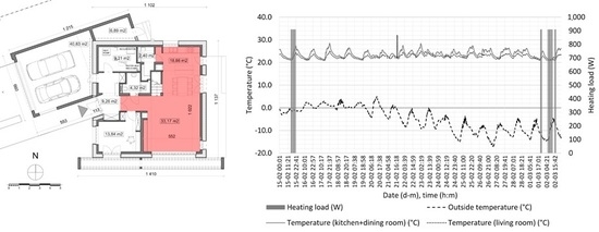
An exemplary series of data recorded from 15 February, 2018 to 2 March, 2018 is presented in
Figure 3. Heating load (W) indicates that the actual temperature in the room was less than the temperature set on the thermostat (assumed indoor temperature) and thus the heating system was activated. Even during the period when the heating system was turned off, the indoor temperature exceeded 20 °C, and occasionally it even reached 28 °C. These temperature increases are the result of excess heat gains occurring in the zone. Periodic overheating can be limited by effective heat storage and the stored energy can be reused later to cover heating energy demand. The theoretical amount of energy stored during the heating season was calculated on the basis of the measurement data and it is presented in
Section 5.
4. Peripheral Heat Storage Tank with PCM
The idea of using the PCM tank for air distribution with air ducts or a mechanical ventilation system is not a new solution. However, in most cases the system has been used for cooling and takes advantage of a discounted electricity tariff during the night-time through peak shaving [
34]. Free cooling with latent-heat thermal energy storage can also be used as an alternative to night-ventilation [
35]. The design of the energy storage system was based on storage tanks used in solar collectors. Moreover, the design of the heat storage system makes the following assumptions:
The storage tank should be light and constructed from materials that are easily available in the market.
The system should be capable of circulating air 3 times within an hour.
The selected phase change material should store heat for as long as the time it would take the temperature in the monitored rooms to fall below a level that would normally turn the heating system on.
Taking these requirements into account, the phase change material was chosen first. The phase change material used in the analysis is paraffin RT24. The melting area is 21–25 °C, with a peak at 24 °C. The total phase change range for the material is from 16 to 31 °C. However, for our study the useful range is from 21 to 26 °C. The enthalpy characteristics for the specific temperature range is presented in
Figure 4. The total amount of latent heat that can possibly be accumulated between 20.5 and 26.5 °C is 104 kJ/kg. The other properties are as follows: heat conductivity 0.2 W/(m
2·K), and density 880 kg/m
3 (solid state) and 770 kg/m
3 (liquid state). The reason for choosing this phase change material was its thermal characteristics, particularly its enthalpy in the given temperature range. Paraffin RT24 is characterized by having the highest heat storage capacity in the 23.5–24.5 °C range. According to the manufacturer (Rubitherm GmbH, Berlin, Germany), the total heat storage capacity for the range of 20.5–26.5 °C is 104 kJ/kg and makes up 65% of its total value at 160 kJ/kg [
36].
Then, we defined the method for dynamically simulating the minimal capacity of the heat storage to capture excess heat from unexpected heat gains (more sunny days in winter or using the fireplace instead of electric heating), and store it until it is needed for heating the monitored rooms. Subsequently, the required volume of the phase change material was calculated. The length of the rods was chosen so that they would contain a predefined amount of phase change material in an arrangement that enabled the free flow of air.t The length of the copper rods was the basis for deciding the size of the oblong cylinder.
The authors proposed a novel heat gain storage system in the peripheral PCM tank, the scheme of which can be seen in
Figure 5. The installation consists of an air intake, a turbine with a maximal airflow of 420 m
3/h, which corresponds to 3 air changes per hour for the living area (living room and kitchen), a PCM heat storage, air ducts, an acoustic damper, and an air exhaust in the living room. The heat storage tank was designed as a cylinder built from two steel plate shells, filled with polyurethane or aerogel thermal insulation. The external diameter of the cylinder is 54 cm and the length is 80 cm. The internal envelope was fitted with steel rods and 137 of 20-mm copper tubes filled with PCM were fitted to them. To optimally use the volume of the tank, 8 additional 15-mm tubes were placed inside. The length of all tubes is 61 cm. The top and bottom of the cylinder were constructed and insulated like the sides of the cylinder. Two 160-mm stub pipes were placed in the geometrical centre of the circle. The total volume of PCM is 0.027 m
3, while the maximum energy capacity of the storage tank is 848 kJ.
The storage tank works through the airflow in the container and the copper pipes are filled with PCM. Unidirectional flow is achieved thanks to the turbine controlled by the BMS. The duration and speed of rotation is chosen so that heat is absorbed from the air and stored in the PCM while the average air temperature in the kitchen, the living room and the dining room is at least 1 K higher than the temperature set on the thermostat, despite the heating system being turned off. When the temperature in the room falls below the temperature on the thermostat, the recovery heat from the storage tank is used. Later, when the PCM tank is discharged, the heating system turns on. The installation is equipped with an acoustic damper so that the airflow can barely be heard.
5. Theoretical Effectiveness of the PCM Storage Tank
The analysis of the stored heat gain was conducted for three rooms of the building described in
Section 3: the kitchen, the dining and living room. The calculations presented below were performed using real data from measurements conducted between February 2017 and February 2018. For the entire period, excess heat gain (SEHG) was defined as the sum of all temporary heat gains. According to Equation (1), TEHG is positive if the temperature increases during a single time step with respect to the previous time step and the temperature is higher than the base temperature (20 °C). The assumption is made that it is possible to accumulate excess heat gain and utilise it later. The device filled with RT24 described in
Section 4 was used in the storage tank. The SEHG values achieved in the entire heating season can be seen in
Figure 6, except for the intervals when they were equal to 0. The values were defined in 10-min time steps. The average TEHG value for the entire heating season was 19.3 kJ.
It is important to note that these values only refer to the three rooms that belong in the day zone of the building.
Figure 7 shows the temporary level of charge of the PCM storage tank. Maximal values are the result of limiting the energy capacity of the storage tank, set as 848 kJ and achieved independently during the time period. As seen in
Figure 7, the storage tank is effectively used throughout the entire duration of the analysis period, particularly in the winter months from December to February. The changes show that the storage tank is regularly charged and discharged, with hardly any periods when it is not in use. The period of zero values in March is due to no measurement data as a result of faulty measuring equipment. The total amount of heat stored and released into the room is dependent on the assumed airflow. The value of SEHG achieved during the heating season is 88 MJ assuming an airflow of 140 m
3/h, which corresponds to air exchange only in the kitchen and the living room. Increasing the airflow to the maximal throughput of exchanger (420 m
3/h), improves the stored energy potential to 208 MJ, which corresponds to an electricity reduction of 33%.
The temperature history of the PCM in the storage tank is presented in
Figure 8. It can be noticed that material is working above 21 °C which is the set point that is determined by the indoor temperature. The container is charged or the energy can be regained when the indoor temperature is above the set point. The maximum value of the PCM temperature is below 26 °C. This means that the material is not overloaded during the whole period of time that was analysed. This is confirmed by the results presented in
Figure 9. The melting fraction of PC is below, but almost 1.0. The lower limit is around 0.45. This is an effect of the PCM temperature in the tank, which is above 21 °C. In that case, some of the paraffin is melted.
An additional study was devoted to a numerical analysis of the analysed building and other scenarios. This analysis enabled us to determine the heat gain storage potential for other building construction solutions, including timber frame constructions (low thermal mass). It is expected that the efficiency of heat gain storage in lightweight construction buildings will be much higher than in the case of heavily constructed buildings. For the comparative analysis, the results from the building energy performance simulation was used. A model of the existing building was developed in the simulation programme Design Builder (uses the EnergyPlus dynamic simulation engine), in accordance with the actual state, that is, a heavy construction. An airflow of 140 m3/h between the heat storage unit and the rooms was assumed. The calculation model was calibrated so that the SEHG values achieved from the simulation and real measurement data were the same. The calibration was done by choosing an appropriate heat gain scenario. The calculations were performed using a 1-hour time step for climate data for a typical meteorological year at the location of the existing building. The next calculation was performed for a building with a light construction, in which massive masonry walls, concrete slabs, floors and ceilings were substituted with an entirely timber construction. The calculations were repeated using the lightweight construction building model. The obtained SEHG was 116 MJ, and an average TEHG of 23.9 kJ. Assuming a maximum air throughput in the exhaust at 3 air changes per hour for the analysed room (420 m3/h), the SEHG value was 273 MJ. In comparison with the heavily constructed building, the value of SEHG increased by about 30%.
6. Conclusions
This study investigates the possibility of storing internal heat gains to stabilise internal air temperatures during the heating or cold season. A method for defining excess heat gains (temporary TEHG and seasonal SEHG) on the basis of internal temperature measurement data from a thermal zone with controlled environment parameters was proposed. The proposed technical solution was a small peripheral heat storage tank connected to the air ventilation circuit using phase change materials. The energy potential of this solution was defined on the basis of measurement data from a passive, ultra-low-energy building, with a heavy construction in continental climate conditions.
The proposed peripheral heat storage tank connected with a heat exchanger contained 0.027 m3 of phase change material, RT24. The analysis of energy efficiency showed that a storage tank designed in this way could effectively store short-term internal heat gains from the building’s zone. Charging and discharging of the storage tank occurred practically in a 24-hour cycle, and in the winter season it achieved full charge on multiple occasions. The house was designed to minimize overheating of the building in the summer, for example, the southern canopy is used to protect the windows from direct solar radiation. Due to the change in the sunlight angle of incidence during the year, direct solar radiation penetrates into the interior in winter, which is utilised as an additional heat gain. In such a situation, the indoor temperature may increase and users open the window causing losses of unused energy. For these reasons, in today’s homes it is helpful to encourage residents to appropriate behaviour of so that they have an impact on final energy consumption.
The paper analysed an ultra-low-energy building under continental climatic conditions. Based on the measurement data from the BMS, the yearly energy consumption for three rooms was 156.4 kWh/a (563.0 MJ/a). By using the proposed heat recovery system combined with a thermal storage tank, the yearly energy savings are 51.9 kWh/a (187.0 MJ/a), or around 33%. This device has the additional task of ensuring proper thermal comfort. In building with high air tightness and low energy demand for heating, any additional heat gains, e.g., resulting from the recreational use of the fireplace, result in excessive temperature increases. In the summer, this type of device complements the systems that increase the protection against overheating.
The proposed solution is related to a specific case, however, it shows the potential of employing this type of storage tank, especially in energy efficient and passive buildings where temporary (even during the heating/cold season) heat gains significantly exceeded heat losses. The expected energy effect could be much higher in the case of timber frame constructions with a much lower thermal inertia. Based on the simulation analysis, the achieved differences in SEHG values between a heavy and a lightweight building were about 30%. It is important to keep in mind that a building with different energy characteristics might require adjusting the parameters of the heat storage tank, including its size and the amount of PCM used.
Although similar solutions have been applied to the storage of thermal energy from solar collectors, this paper proposes an innovative method for their future use.


