Design of Laminated Seal for Triple Offset Butterfly Valve (350 °C) Used in Combined Cycle Power Plants


Abstract
:1. Introduction
2. Materials and Methods
2.1. Operating Principle and Theoretical Analysis of Triple Offset Butterfly Valve
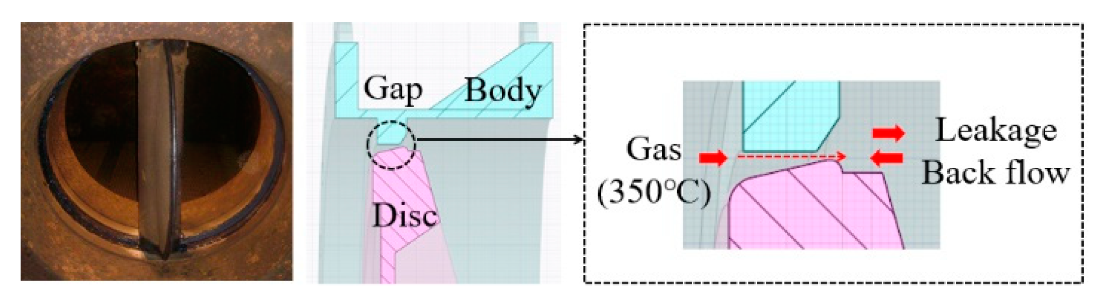
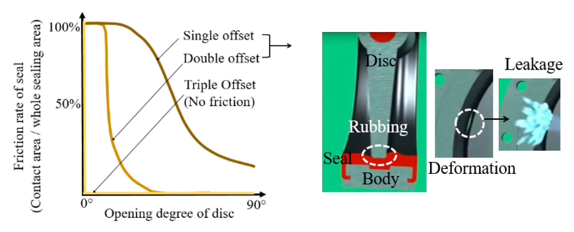
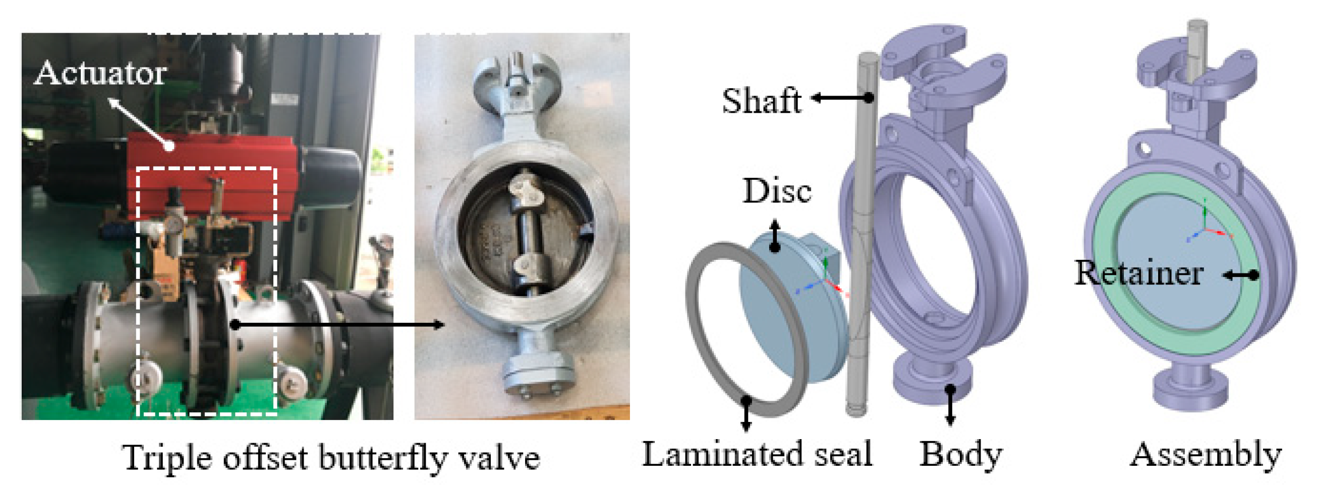
2.1.1. Structure of Triple Offset Butterfly Valve
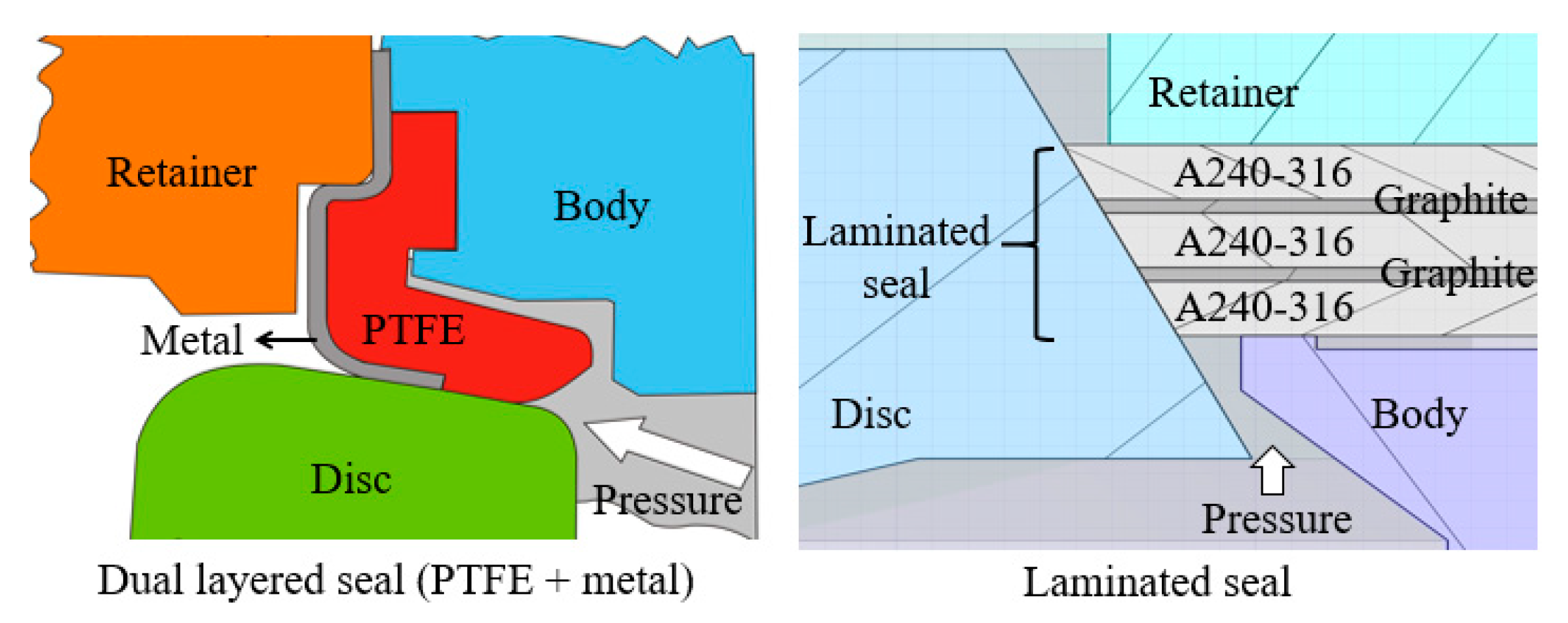
2.1.2. Sealing Mechanism of Laminated Seal
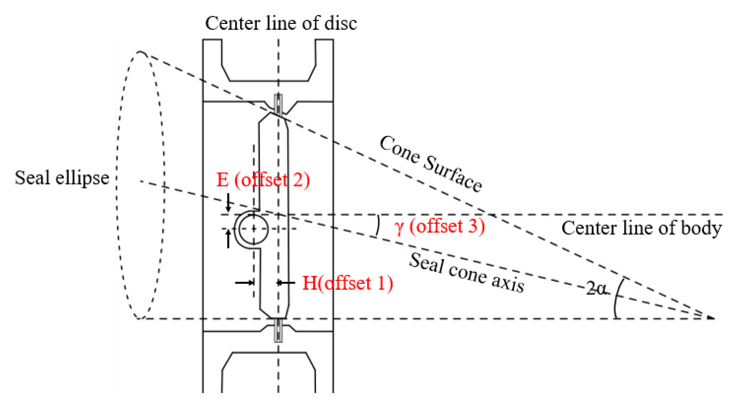
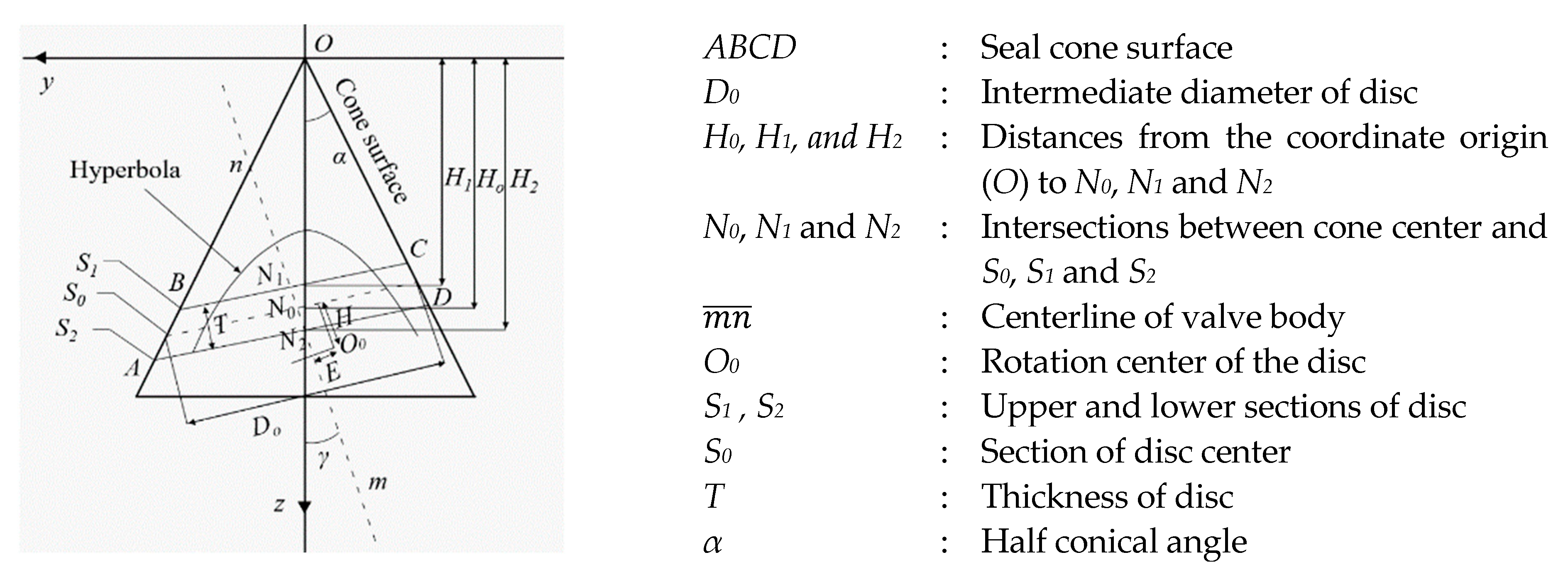
2.1.3. Mathematical Modeling of TOBV Seal Pair
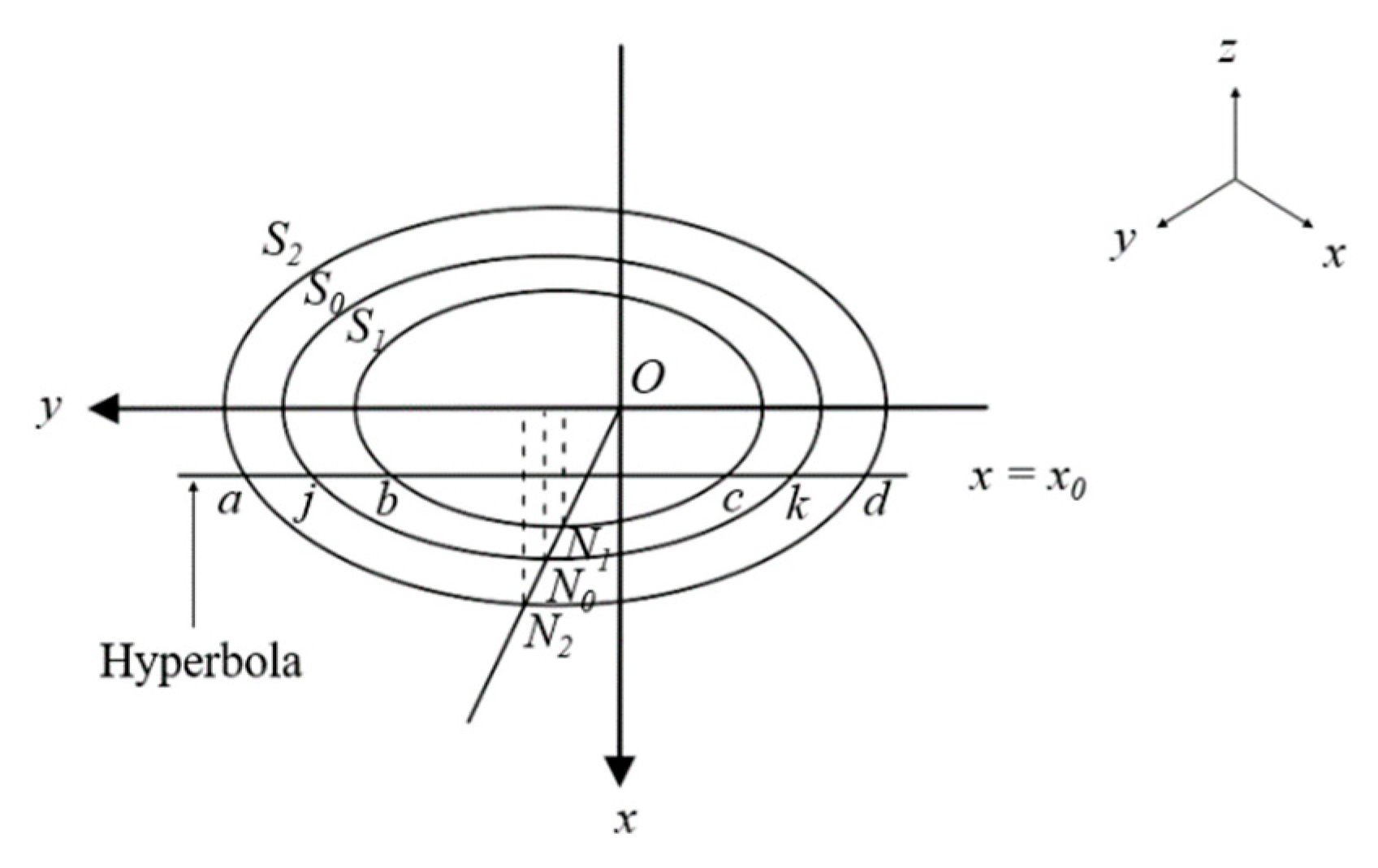
2.1.4. Calculation of Slope Angle at Contact Surface
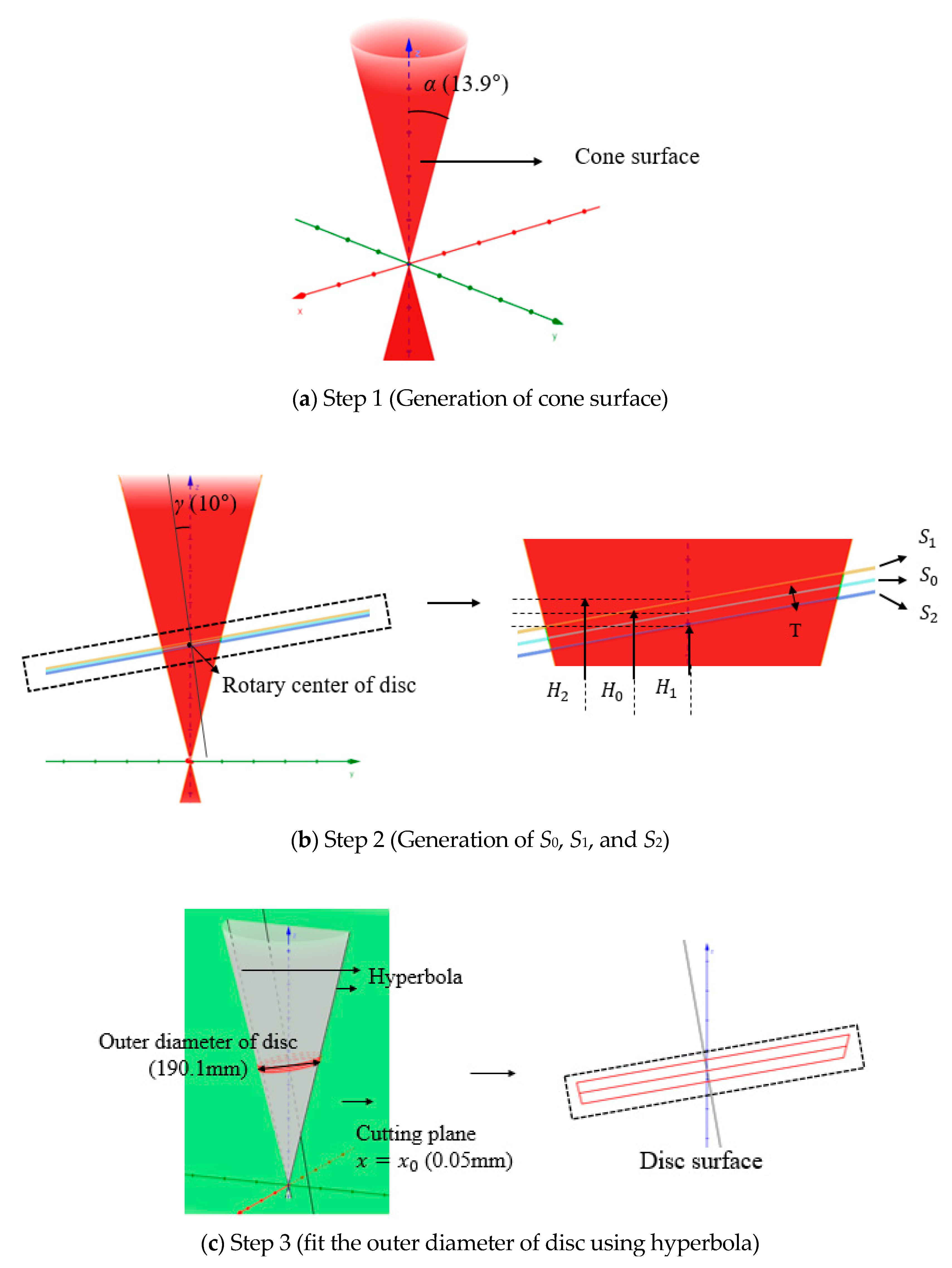
- (Step 1)
- Cone surface is generated by inputting α (13.9°) using Equation (3), as shown in Figure 9a.
- (Step 2)
- When γ (10°), disc thickness (15 mm) is given, H0 = 369.9 mm, H1 = 377.5 mm, H2 = 362.3 mm and rotary center of disc is obtained from Equation (5), and then S0, S1, and S2 are generated using Equation (4), as shown in Figure 9b.
- (Step 3)
- The cone surface is cut by x = x0 (0.05, green plane) to obtain hyperbola in Equation (6), which enables the outer diameter of disc to be 190.1 mm, and then the disc surface is obtained as shown in Figure 9c.
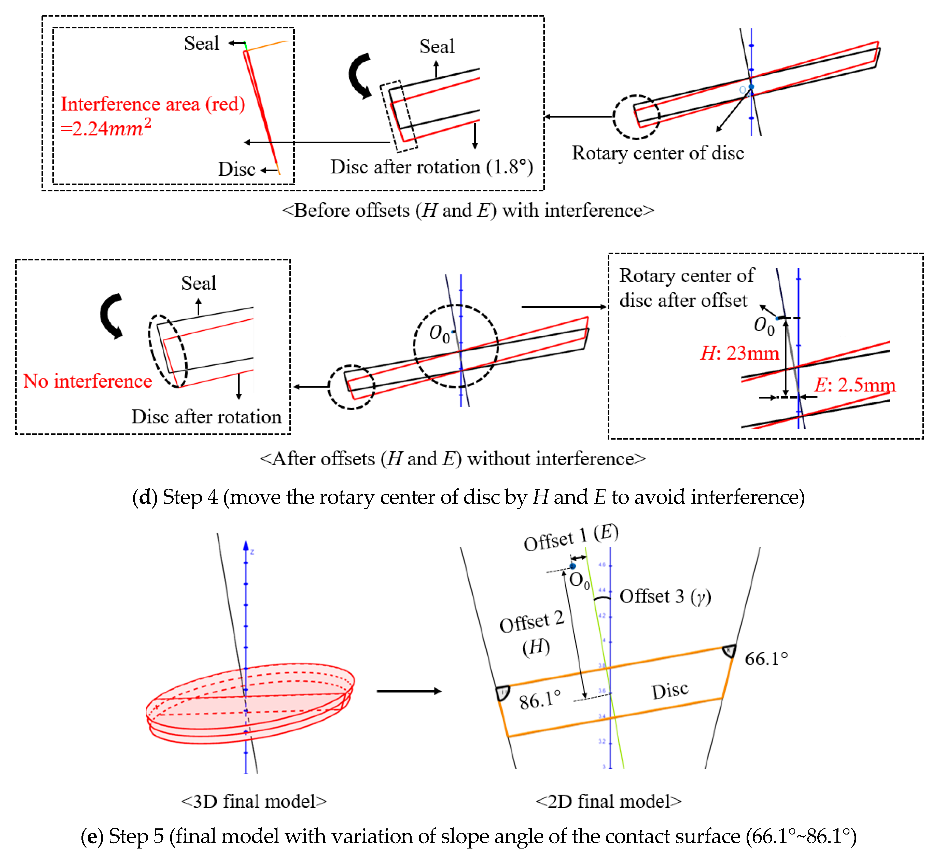
- (Step 4)
- Rotary center of the disc moves by the eccentricity H (23 mm) and E (2.5 mm) to avoid interference between the seal and the disc during opening and closing, as shown in Figure 9d.
- (Step 5)
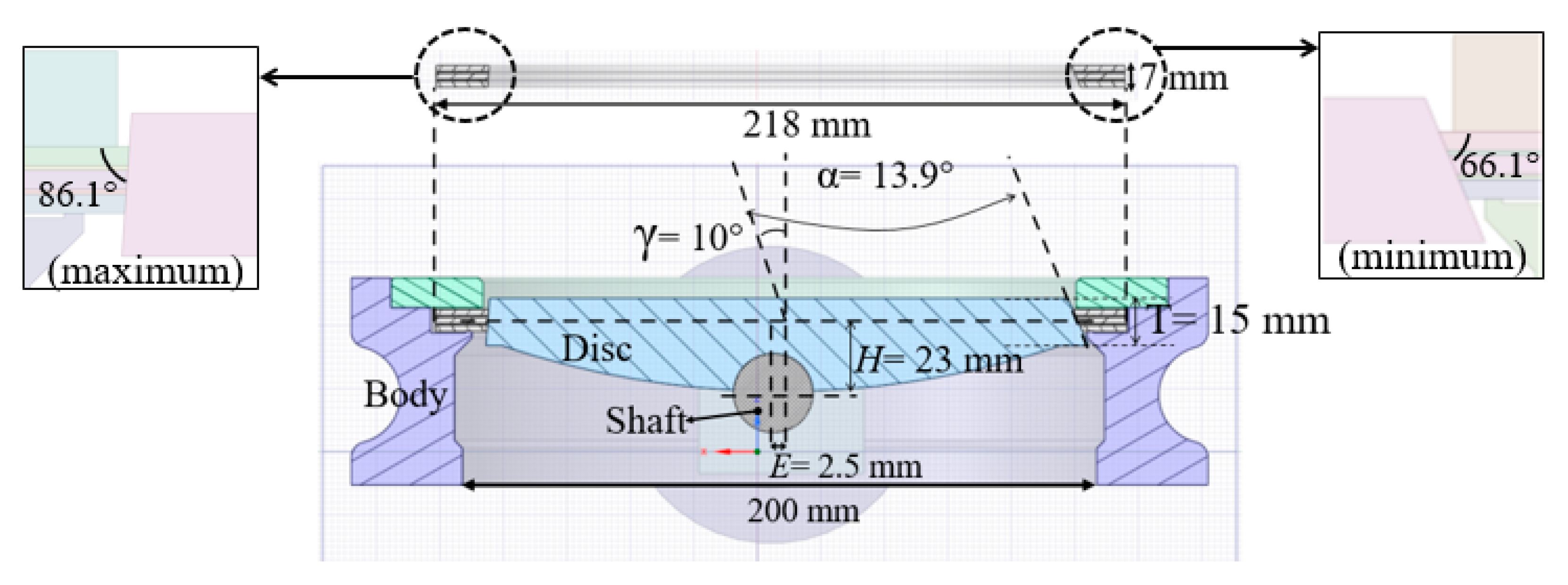
- The eccentric angle of 10° (γ) of the final triple offset model results in the variation of the slope angle of the contact surface from 66.1° (minimum angle) to 86.1° (maximum angle) in the tangential direction, as shown in Figure 9e.
2.2. Finite Element Analysis
2.2.1. Geometry and Analysis Conditions
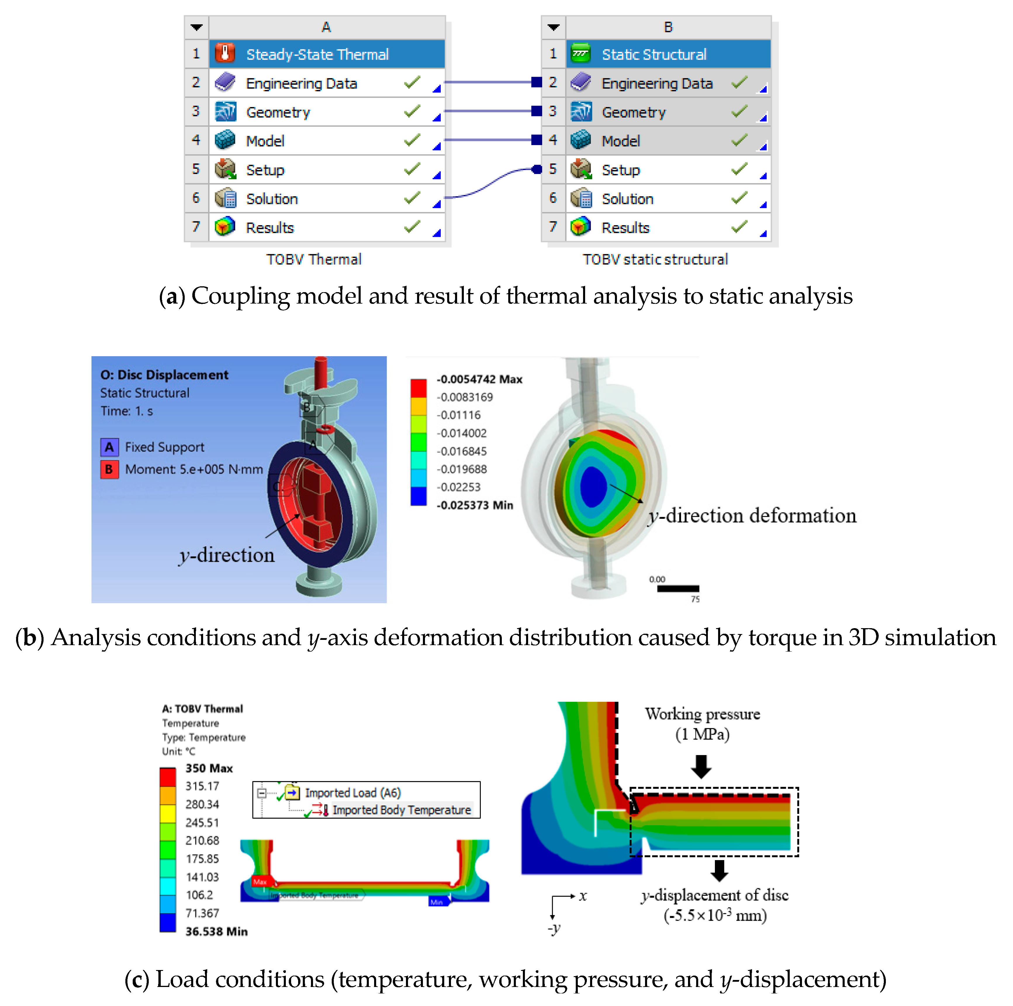
2.2.2. Results of the Thermal-Structural Analysis
2.2.3. Discussions—Effect of Graphite on Sealing Ability
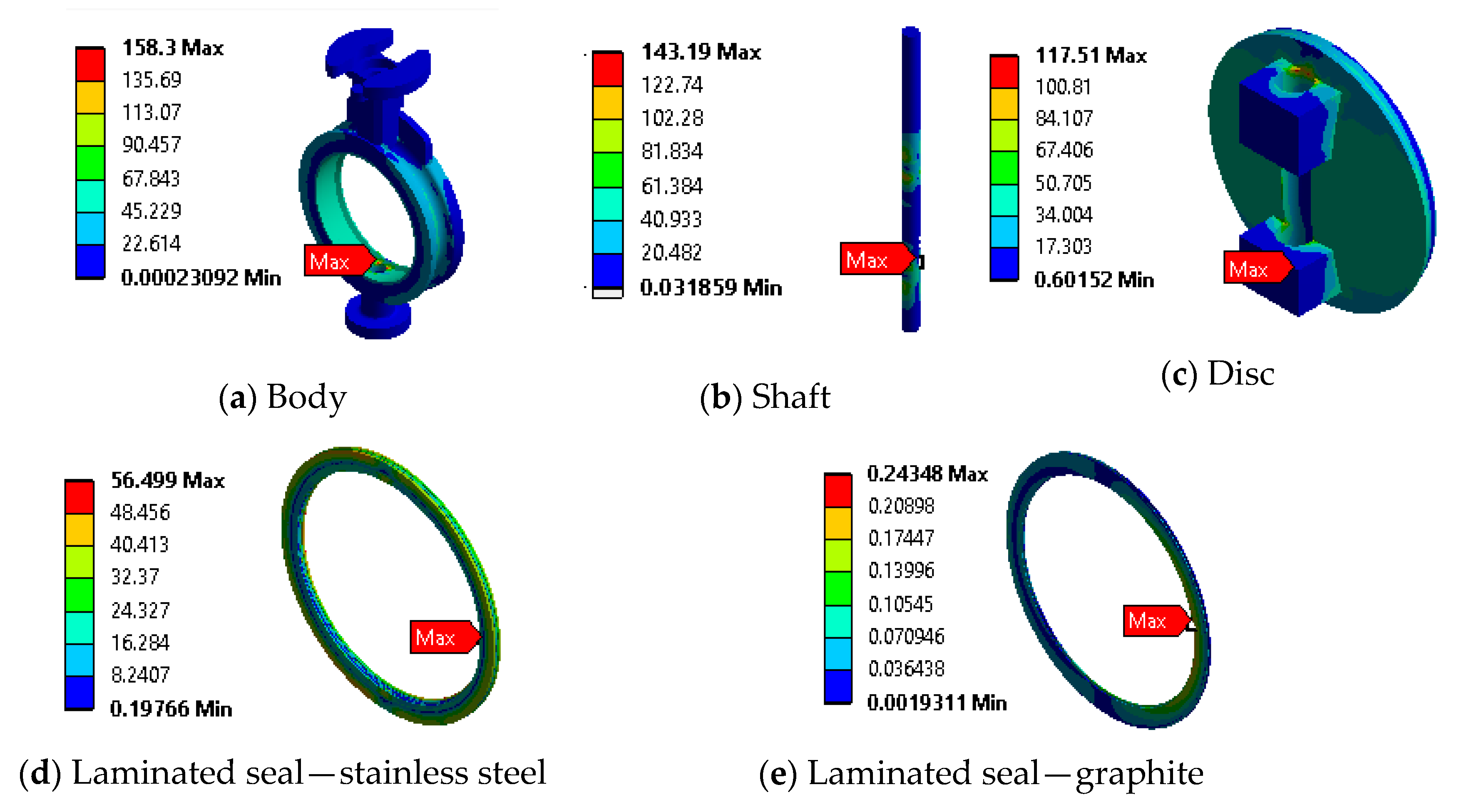
2.2.4. Verification of Structural Safety of the Proposed TOBV
3. Prototype and Performance Test
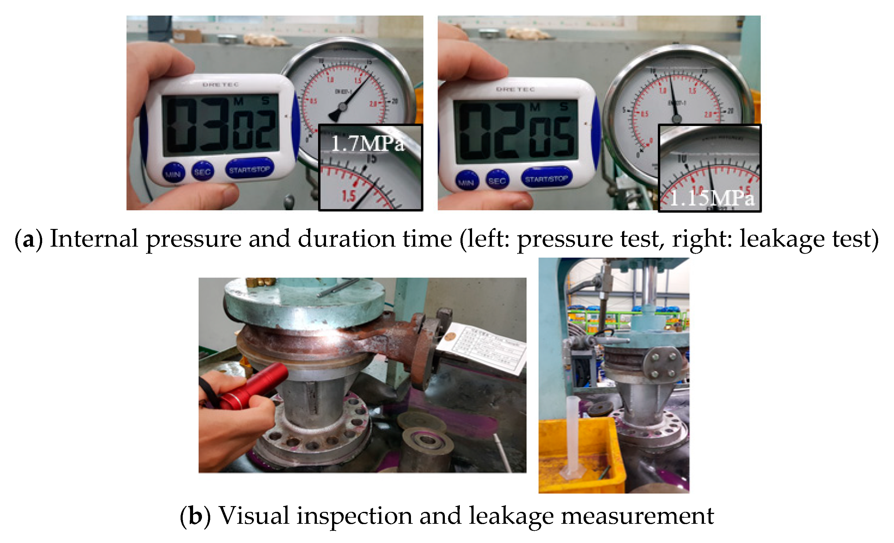
3.1. Internal Pressure and Leakage Tests
3.2. Field Test of Proposed TOBV in CCPPs
4. Conclusions
- (1)
- When the TOBV has the inner diameter of the pipe: 200 mm, the diameter of disc: 190.1 mm, the outer diameter of seal: 218 mm, and the thickness of disc: 15 mm, the three eccentricities (offset 1: 2.5 mm, offset 2: 23 mm, offset 3: 10°) were specified based on the international regulation, and the slope angles of contact surface (66.1° (minimum angle)~86.1° (maximum angle)) for eliminating rubbing were calculated.
- (2)
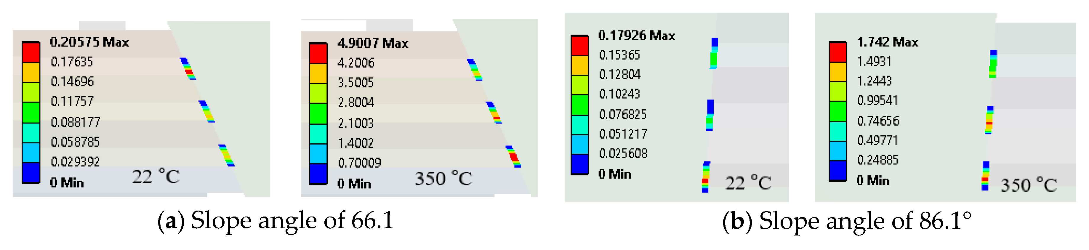
- Thermal-structural coupled analyses were conducted for the different seal designs (the number of seal layers and graphite thicknesses), temperatures (25 °C and 350 °C), and slope angles (66.1° and 86.1°), and the maximum contact stresses’ behaviors at the contact surfaces were investigated as follows:
- -
- It was observed that the increases of contact surface led to a reduction of the peak contact stress, so that sealing performance was improved with increasing temperature as a result of thermal expansion.
- -
- In respect to the graphite layers, leakages were expected for the all models at 25 °C (Gmin: 0.19~0.28 MPa, Gmax: 0.14~0.18 MPa), and there were small changes in contact stress by varying the amount of the graphite, whereas at 350 °C, the larger contact stresses (Gmin: 12.33~4.73 MPa, Gmax: 5.03~0.79 MPa) beyond the working pressure were observed, which means that the graphite showed a sealing ability at the high temperature rather than at the room temperature.
- -
- In respect to the stainless steel layers, the graphite did not withstand the contact force at 25 °C, so it was intensively applied on the stainless steel whose surface was decreased as the amount of the graphite was increased, and then the contact stresses at the stainless steel were increased (SSmin: 2.0 MPa → 6.3 MPa, SSmax: 1.2 MPa → 4.9 MPa). While at 350 °C, the contact force was distributed to the graphite, and the peak contact stress at the stainless steel was reduced (SSmin: 169.2 MPa → 74.13 MPa, SSmax: 129.9 MPa → 63.0 MPa) as the amount of graphite was increased.
- -
- The 7-layer model (graphite thickness: 0.8 mm, stainless thickness: 1.15, total thickness of seal: 7 mm, the slope angles of contact surface: 66.1° and 86.1°) was suggested to guarantee not only airtightness, but also smooth rotation of the disc.
- (3)
- More laminated layers of the graphite decreased the contact stresses in both graphite and stainless steel at 350 °C, but opposite behavior was observed at −196 °C, which means the graphite is in charge of improving driving performance of the disc at the high temperature and sealing ability at the cryogenic temperature.
- (4)
- In the field test, which was implemented for three months in CCPPs, the temperature (32 °C) in the rear end of the new model decreased by 20%, compared with that of the conventional one (40 °C), which demonstrates that the proposed laminated seal improved the sealing ability of the TOBV, and its durability and suitability for the actual working environment were verified.
Author Contributions
Funding
Acknowledgments
Conflicts of Interest
Abbreviations
| CCPP | Combined Cycle Power Plants |
| SOBV | Single Offset Butterfly Valve |
| DOBV | Double Offset Butterfly Valve |
| TOBV | Triple Offset Butterfly Valve |
| PTFE | Polytetrafluoroethylene |
| ASME | The American Society of Mechanical Engineers |
| API | American Petroleum Institute |
References
- Choi, M.G.; Ryu, J.Y. Numerical Study of the Axial Gap and Hot Streak Effects on Thermal and Flow Characteristics in Two-Stage High Pressure Gas Turbine. Energies 2018, 11, 2654. [Google Scholar] [CrossRef]
- Almutairi, A.S.; Pilidis, P.; Al-Mutawa, N. Energetic and Exergetic Analysis of Combined Cycle Power Plant: Part-1 Operation and Performance. Energies 2015, 8, 14118–14135. [Google Scholar] [CrossRef]
- Rao, A.D. Combined Cycle Systems for Near-Zero Emission Power Generation; Woodhead Publishing: Cambridge, UK, 2012; pp. 1–43. [Google Scholar]
- Shiraishi, K.; Ono, Y.; Yamashita, Y.; Sakamoto, M. Energy Savings through Electric-assist Turbocharger for Marine Diesel Engines. Mitsubishi Heavy Ind. Tech. Rev. 2015, 52, 36–41. [Google Scholar]
- Najjar, Y.S.H.; Ismail, M.S. Optimum Pressure Ratios for Different Gas Turbine Cycles. High Temp. Technol. 1990, 8, 283–289. [Google Scholar] [CrossRef]
- Brito-Melo, A.; Gato, L.M.C.; Sarmento, A.J.N.A. Analysis of Wells turbine design parameters by numerical simulation of the OWC performance. Ocean Eng. 2002, 29, 1463–1477. [Google Scholar] [CrossRef]
- Falcao, A.D.O.; Vieira, L.C.; Justino, P.A.P.; André, J.M.C.S. By-pass air-valve control of an OWC wave power plant. J. Offshore Mech. Arct. Eng. 2003, 125, 205–210. [Google Scholar] [CrossRef]
- Zanger, J.; Widenhorn, A.; Aigner, M. Experimental Investigations of Pressure Losses on the Performance of a Micro Gas Turbine System, ASME. J. Eng. Gas Turbines Power 2011, 133, 082302. [Google Scholar] [CrossRef]
- Amano, R.S.; Draxler, G.R. High-pressure steam flow in turbine bypass valve system Part 1: Valve flow. J. Propuls. Power 2002, 18, 555–560. [Google Scholar] [CrossRef]
- Khan, M.N.; Tlili, I. Performance Enhancement of a Combined Cycle Using Heat Exchanger Bypass Control: A Thermodynamic Investigation. J. Clean. Prod. 2018, 192, 443–452. [Google Scholar] [CrossRef]
- Stankus, S.V.; Yatsuk, O.S.; Zhmurikov, E.I.; Tecchio, L. Thermal expansion of artificial graphites in the temperature range 293–1650 K. Thermophys. Aeromech. 2012, 19, 463–468. [Google Scholar] [CrossRef]
- Manhani, G.B.; Pardini, C.L.; Neto, F.L. Assessment of tensile strength of graphites by the Iosipescu coupon test. Mater. Res. Ibero Am. J. Mater. 2007, 10, 233–239. [Google Scholar]
- Zhao, C.Y.; Wu, Z.G. Heat transfer enhancement of high temperature thermal energy storage using metal foams and expanded graphite. Sol. Energy Mater. Sol. Cells 2011, 95, 636–643. [Google Scholar] [CrossRef]
- Chen, B.; Fan, Y.G. 3D modeling and Open-close Motion Simulation of the Triple Eccentric Butterfly Valve. Adv. Mater. Res. 2011, 215, 191–194. [Google Scholar] [CrossRef]
- Liang, R.; Jiang, F.; Zhou, X.H.; Yu, S.R.; Du, Z.N. Three-dimension Analysis of the Three-eccentricity Butterfly Valve Metal Seal Pair Interference. Fluid Mach. 2003, 8, 5. [Google Scholar]
- Kan, B.; Ding, J. Criterion for non-interference of solid metal seal pair in double-offset butterfly valve. J. Braz. Soc. Mech. Sci. Eng. 2016, 38, 1745–1752. [Google Scholar] [CrossRef]
- Dev, B.; Samudrala, O.; Wang, J. Characterization of leak rates in thermoplastic barrier valve seals under high static and cyclic pressure loads. J. Pet. Sci. Eng. 2016, 145, 279–289. [Google Scholar] [CrossRef]
- Lei, J.P.; E, J.Q.; Chen, J.M.; Zhang, Y.; Zeng, E.Q.; Chen, H.Z.; Liu, H.; Guo, L.; Su, J.X. Finite element analysis of seal performance for new type rotating ball valve with double direction metal sealing. J. Cent. South Univ. Sci. Technol. 2010, 43, 1345–1350. [Google Scholar]
- Ahn, J.T.; Lee, K.C.; Lee, K.H.; Han, S.H. Investigation of the Mechanical Behavior of a Flexible Solid Metal Seal for a Cryogenic Butterfly Valve. J. Mech. Sci. Technol. 2011, 25, 2393–2400. [Google Scholar] [CrossRef]
- Feyzullahoğlu, E. Abrasive wear, Thermal and viscoelastic behaviors of rubber seal materials used in different working conditions. Proc. Inst. Mech. Eng. Part J J. Eng. Tribol. 2015, 229, 64–73. [Google Scholar] [CrossRef]
- Phull, H.S. New developments in triple-offset butterfly valves. World Pumps 2004, 456, 40–44. [Google Scholar] [CrossRef]
- Burdick, M.D.; Zweig, B.; Moreland, R.E. Linear Thermal Expansion of Artificial Graphites to 1370° C. J. Res. Natl. Bur. Stand. 1951, 47, 35–40. [Google Scholar] [CrossRef]
- ASME. ASME. ASME Boiler and Pressure Vessel Code, Section II—Materials. In ASME Boiler and Pressure Vessel Code; ASME: New York, NY, USA, 2013. [Google Scholar]
- American Water Works Association. American Water Works Association (AWWA) Manual M49, Butterfly Valves: Torque, Head Loss, and Cavitation Analysis, 2nd ed.; American Water Works Association: Mumbai, India, 2012. [Google Scholar]
- Kwak, H.; Seong, H.; Kim, C. Design of laminated seal in cryogenic triple-offset butterfly valve used in LNG marine engine. Int. J. Precis. Eng. Manuf. 2019, 20, 243–253. [Google Scholar] [CrossRef]
- ASME. B.16.34 Valves-Flanged, Threaded, and Welding End; ASME: New York, NY, USA, 2014. [Google Scholar]


| Diameter of the disc (mm) | 190.1 | Offset 1, E (mm) | 2.5 |
| Thickness of disc, T (mm) | 15 | Offset 2, H (mm) | 23 |
| Outer diameter of the seal (mm) | 218 | Offset 3, γ (°) | 10 |
| Thickness of seal (mm) | 7 | Half conical angle, α (°) | 13.9 |
| 1-Layer Model | 3-Layer Model | 5-Layer Model | 7-Layer Model | ||||
|---|---|---|---|---|---|---|---|
| Stainless Steel | Graphite | Stainless Steel | Graphite | Stainless Steel | Graphite | Stainless Steel | |
| Thickness (mm) | 7 | 0.6 | 3.20 | 0.6 | 2.13 | 0.6 | 1.45 |
| 0.8 | 3.10 | 0.8 | 2.07 | 0.8 | 1.39 | ||
| 1.0 | 3.00 | 1.0 | 2.00 | 1.0 | 1.55 | ||
| 1.2 | 2.90 | 1.2 | 1.93 | 1.2 | 1.36 | ||
| Carbon | ≤0.08% | Silicon | ≤1.0% | Manganese | ≤2.0% |
| Phosphorous | ≤0.045% | Sulphur | ≤0.030% | Nickel | 10~14% |
| Chromium | 16%~18% | Molybdenum | 2%~3% | Iron | 61.8%~72% |
| (a) Thermal Conductivity | |||||
| Temperature (°C) | Thermal Conductivity (W/m·°C) | ||||
| A240–316 | A216 WCB | Graphite | |||
| 25 | 14.1 | 11.5 | 108.4 | ||
| 100 | 15.4 | 12.7 | 106.5 | ||
| 200 | 16.8 | 13.8 | 102.5 | ||
| 250 | 17.6 | 14.3 | 100.3 | ||
| 300 | 18.3 | 14.9 | 98.3 | ||
| 350 | 19.0 | 15.4 | 88.9 | ||
| (b) Thermal Expansion | |||||
| Temperature (°C) | Thermal Expansion ( m/m·°C) | ||||
| A240–316 | A216 WCB | Graphite | |||
| 25 | 0 | 0 | 0 | ||
| 100 | 1.3 | 1.0 | 0.8 | ||
| 200 | 3.1 | 2.3 | 1.8 | ||
| 250 | 4.0 | 3.0 | 1.8 | ||
| 300 | 4.9 | 3.7 | 1.8 | ||
| 350 | 5.9 | 4.5 | 1.8 | ||
| (c) Mechanical Property | |||||
| Temperature (°C) | Elastic Modulus (GPa) | Poisson’s Ratio | |||
| A240–316 | A216 WCB | Graphite | A240–316 A216 WCB | Graphite | |
| 25 | 195 | 202 | 9.83 | 0.29 | 0.21 |
| 100 | 189 | 198 | 9.53 | ||
| 200 | 183 | 192 | 9.53 | ||
| 250 | 179 | 189 | 9.53 | ||
| 300 | 176 | 185 | 9.53 | ||
| 350 | 172 | 179 | 6.619 | ||
| Graphite | SSmin (66.1°) | SSmax (86.1°) | |||
|---|---|---|---|---|---|
| Thickness (mm) | 22 °C | 350 °C | 22 °C | 350 °C | |
| 1-layer | - | 2.00 | 282.17 | 0.64 | 199.71 |
| 3-layer | 0.6 | 2.05 | 169.22 | 1.16 | 129.86 |
| 0.8 | 2.13 | 154.37 | 1.16 | 128.81 | |
| 1 | 2.14 | 124.61 | 1.51 | 115.68 | |
| 1.2 | 2.26 | 115.37 | 1.60 | 95.33 | |
| 5-layer | 0.6 | 3.40 | 118.94 | 1.92 | 104.14 |
| 0.8 | 3.62 | 116.61 | 2.26 | 85.61 | |
| 1 | 3.73 | 113.53 | 2.66 | 79.56 | |
| 1.2 | 3.98 | 104.82 | 2.67 | 76.53 | |
| 7-layer | 0.6 | 3.46 | 122.55 | 2.71 | 68.67 |
| 0.8 | 3.66 | 97.15 | 2.99 | 66.81 | |
| 1 | 5.09 | 74.50 | 4.33 | 64.33 | |
| 1.2 | 6.33 | 74.13 | 4.90 | 63.02 | |
| Graphite | Gmin (66.1°) | Gmax (86.1°) | |||
|---|---|---|---|---|---|
| Thickness (mm) | 22 °C | 350 °C | 22 °C | 350 °C | |
| 3-layer | 0.6 | 0.26 | 12.33 | 0.16 | 5.03 |
| 0.8 | 0.28 | 13.01 | 0.17 | 5.67 | |
| 1 | 0.22 | 8.71 | 0.16 | 4.03 | |
| 1.2 | 0.24 | 7.07 | 0.15 | 3.75 | |
| 5-layer | 0.6 | 0.26 | 8.12 | 0.16 | 3.11 |
| 0.8 | 0.19 | 7.20 | 0.15 | 2.56 | |
| 1 | 0.22 | 5.93 | 0.15 | 2.14 | |
| 1.2 | 0.21 | 5.72 | 0.13 | 2.10 | |
| 7-layer | 0.6 | 0.24 | 7.52 | 0.18 | 2.40 |
| 0.8 | 0.21 | 4.90 | 0.18 | 1.74 | |
| 1 | 0.17 | 3.60 | 0.15 | 0.81 | |
| 1.2 | 0.19 | 2.73 | 0.14 | 0.79 | |
| Comparison Model | Graphite Thickness (mm) | Reduction of Peak Contact Stress | |
|---|---|---|---|
| Slope Angle of 66.1° | Slope Angle of 86.1° | ||
| 1-layer | - | 65.6%↓ | 66.5%↓ |
| 3-layer | 0.6 | 42.6%↓ | 48.6%↓ |
| 0.8 | 37.1%↓ | 48.1%↓ | |
| 1 | 22.0%↓ | 42.2%↓ | |
| 1.2 | 15.8%↓ | 29.9%↓ | |
| 5-layer | 0.6 | 18.3%↓ | 35.8%↓ |
| 0.8 | 16.7%↓ | 22.0%↓ | |
| 1 | 14.4%↓ | 16.0%↓ | |
| 1.2 | 7.3%↓ | 12.7%↓ | |
| Temperature (°C) | Change of Contact Stress as More Layers of Graphite | Purpose of Graphite | |
|---|---|---|---|
| Stainless Steel | Graphite | ||
| 350 | ↓ | ↓ | For improving driving performance |
| −196 | ↑ | ↑ | For improving sealing performance |
| Part | Allowable Strength (MPa) | Maximum Equivalent Stress (MPa) | Yielding |
|---|---|---|---|
| Body | 184.25 | 158.30 | No |
| Shaft | 385.25 | 143.19 | No |
| Disc | 137.35 | 117.51 | No |
| SS | 137.35 | 56.50 | No |
| G | 4.69 | 0.24 | No |
| Internal Pressure (MPa) | Duration Time (s) | Result | ||
|---|---|---|---|---|
| Internal pressure test | Regulation | 1.5 | 160 | No leakage |
| Actual | 1.7 | 182 | ||
| Leakage test | Regulation | 1.1 | 125 | No leakage |
| Actual | 1.15 | 30 |
© 2019 by the authors. Licensee MDPI, Basel, Switzerland. This article is an open access article distributed under the terms and conditions of the Creative Commons Attribution (CC BY) license (http://creativecommons.org/licenses/by/4.0/).
Share and Cite
Kwak, H.S.; Seong, H.; Brilianto, R.M.; Kim, C. Design of Laminated Seal for Triple Offset Butterfly Valve (350 °C) Used in Combined Cycle Power Plants. Appl. Sci. 2019, 9, 3095. https://doi.org/10.3390/app9153095
Kwak HS, Seong H, Brilianto RM, Kim C. Design of Laminated Seal for Triple Offset Butterfly Valve (350 °C) Used in Combined Cycle Power Plants. Applied Sciences. 2019; 9(15):3095. https://doi.org/10.3390/app9153095
Chicago/Turabian StyleKwak, Hyo Seo, Hansaem Seong, Rivaldo Mersis Brilianto, and Chul Kim. 2019. "Design of Laminated Seal for Triple Offset Butterfly Valve (350 °C) Used in Combined Cycle Power Plants" Applied Sciences 9, no. 15: 3095. https://doi.org/10.3390/app9153095
APA StyleKwak, H. S., Seong, H., Brilianto, R. M., & Kim, C. (2019). Design of Laminated Seal for Triple Offset Butterfly Valve (350 °C) Used in Combined Cycle Power Plants. Applied Sciences, 9(15), 3095. https://doi.org/10.3390/app9153095