1. Introduction
The field of metamaterials has emerged over the past 20 years and inspired numerous innovations in optics, electromagnetics e.g., [
1,
2,
3] and more recently in acoustics e.g., [
4,
5,
6]. Phononic crystals and acoustic metamaterials are composites engineered to mold elastic wave dispersion through scattering or local resonances to achieve desired spectral and phase properties such as band gaps around specific frequencies. Phononic crystals are composed of a periodic array of scatterers. The mechanism for the formation of band gaps in phononic crystals is a Bragg-like scattering of waves with wavelength comparable to the dimension of the period of the crystal or the crystal lattice constant [
7]. This characteristic limits the use of phononic crystals as low-frequency filters. However, low-frequency filters can be achieved by using a different class of acoustic metamaterials that comprise a series of locally resonating units which are not necessarily periodic. Liu et al. [
8] demonstrated that such assemblies are capable of muting waves of wavelengths that are orders of magnitude longer than the lattice constant. By tuning the properties of the individual units and their arrangement, the metamaterial can act as a low-frequency band-gap filter (blocking the incoming elastic energy within certain frequency bands) or wedge (converting the mode and diverting the incident wave). The studies of resonators that followed have been mostly parametric in nature and focused on designing elements with strong frequency-coupled characteristics that will yield band gaps about a given center frequency [
9,
10,
11].
As noted above, the field of elastodynamic metamaterials is relatively new, but nonetheless presents a wide variety of resonator design methodologies [
9,
10,
11,
12,
13]. An experiment conducted by Rupin et al. [
14] found that cylindrical rods adhered to a plate waveguide could be used to prohibit the propagation of the A0 Lamb wave mode at low frequencies (<11 kHz). Soon thereafter, a paper by Williams et al. [
15] sought to determine what characteristic of the cylindrical rods contributed to the A0 Lamb wave mode band gap. They found that the rods vibrated in an axial mode which applied a “clamping”-like effect to the waveguide. That is, the rods would vibrate in such a way that the out-of-plane displacement at their bases was minimized. They also compared the frequencies at which the minimal displacements occurred with the band gaps reported in Rupin et al.’s paper and found a good agreement between the two spectra.
The spectrum detailed in Williams et al.’s paper was calculated using a vibration model subjected to a harmonic forcing function. Upon further investigation, we found that the frequencies at which minimum displacement occurred were equal to the resonant frequencies of an axially vibrating, fixed-free beam. Since these resonant frequencies have well-known solutions, this finding presented itself as a very straightforward method for designing sub-wavelength resonators for the A0 Lamb wave mode to create band gaps around specific frequencies. However, this approach was only shown to be effective for low-frequency A0 Lamb wave modes which have primarily out-of-plane displacement. The purpose of this article is to extend this concept to design resonators that prohibit the propagation of low-frequency S0 Lamb wave modes and to determine its applicability at higher frequencies. To accomplish this, two resonator designs, one designed based on a frequency matching approach and the other based on the sole concept of clamping, were tested to see how well they can impede the propagation of a 50 kHz S0 Lamb wave. These resonators are hereafter referred to as the frequency-matched resonators and the clamping resonators, respectively. While the design of the frequency-matched resonators is straightforward (based on resonance), the theoretical basis for the design of the clamping resonators is more involved and requires the full attention of a separate publication. We believe that a rational design protocol is possible and will use the experimental results provided herein to demonstrate it in a subsequent publication. Thus, in this article we simply provide finite-element simulations to qualitatively confirm the experimental findings.
2. Experimental Setup
For the experiment, the consistency of various experimental parameters was prioritized to obtain a comparison between the resonator types. That is, various experimental parameters are the same regardless of the resonators being tested. This includes the transducer positions, waveguide dimensions, resonator spacing/positioning, the area of contact between the resonator and plate, resonator material properties, and overall resonator mass. The only difference between tests is the shape of the resonators.
The guided waves that will be used for the test are the S0 Lamb wave mode with a 50 kHz 5-cycle pulse, which corresponds with a wavenumber of 58.1 rad/m. At these low frequencies, this mode corresponds with a wave-structure (i.e., displacement profile) that is effectively planar and consists of in-plane displacement through the thickness of the plate waveguide. The S0 Lamb wave mode was excited and received using shear transducers with the polarization aligned with the wave-propagation direction. A schematic of the setup, including transducer placement and resonator positions, is shown in
Figure 1. Three rows of ten resonators were used for the resonator array and adhered to the surface of the waveguide using cyanoacrylate adhesive. The spacing of the resonator array shown in
Figure 1b is based on how close together the clamping resonators could be positioned.
The main method of assessing the resonators will be to compare two-dimensional fast Fourier transforms (2DFFTs) of the signal transmitted past the resonator array [
16]. The receiving transducer was moved away from the resonator array in 2 cm increments. This was done 20 times to measure an A-scan at 20 positions along the expected wave-propagation direction. For the 2DFFT, zero-padding was applied to increase the number of bins in the wavenumber spectrum, but no zero-padding was applied for the frequency spectrum.
3. Frequency-matched Resonators
Analogous to Rupin et al.’s [
14] axial rod design, the frequency-matched resonator was designed to vibrate at 50 kHz in a flexural mode under fixed-free boundary conditions. The fixed boundary condition was expected to apply the desired clamping effect described in Williams et al. [
15]. The refined design of these frequency-matched resonators consists of a 7.9 × 7.9 mm square rod that is 23.4 mm long.
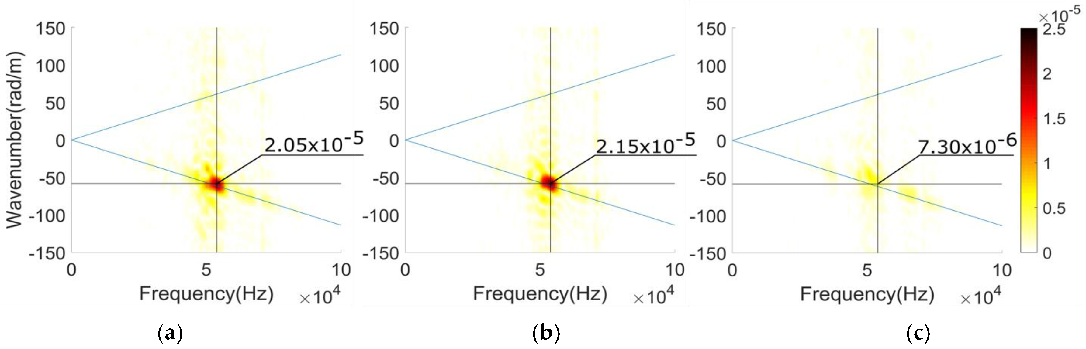
Figure 2a shows the 2DFFT of a baseline measurement which was taken prior to bonding the resonators to the plate waveguide. The peak at a wavenumber of −58.1 rad/m and a frequency of 53.9 kHz shown in
Figure 2a indicates that the S0 mode is being excited.
The Frequency-matched Resonators were positioned on the waveguide as shown in
Figure 1 and adhered to the plate waveguide. The A-scans described in section 2 were measured and used to calculate the 2DFFT shown in
Figure 2b.
When comparing
Figure 2a to
Figure 2b, the frequency-matched resonators do not reduce the transmitted S0 signal. This is believed to be due to the resonators vibrating differently than expected. That is, unlike the axial vibration described in Williams et al., the flexural vibration of the frequency-matched resonator is likely to cause unwanted out-of-plane displacement.
The frequency-matched resonators are an attempt at designing resonators based on resonant frequency, but as shown, it was not an effective approach for this application. In the next section, we propose a clamping resonator that was designed to effectively clamp the S0 wave’s in-plane motion without introducing unwanted out-of-plane displacements. That is, we focused on how the resonator clamps the surface of the waveguide.
4. Clamping Resonators
The clamping resonators (shown in
Figure 3) were designed using symmetry as a means to reduce the unwanted displacement components. The resonators are composed of a center cube with a side length of 7.9 mm, and four cylindrical “arms” that are 4.8 mm in diameter and 15 mm long. These components are joined using cyanoacrylate adhesive so that the resonator shown in
Figure 3 is built. The arms perpendicular to the wave-propagation direction are meant to clamp the in-plane displacement, while the arms parallel to the wave-propagation direction are meant to reduce the unwanted out-of-plane displacement. All these arms undergo flexural vibration, presumably at the same frequency as the propagating wave, to achieve this effect. The guiding principles of the conceptual design were achieved through a combination of theoretical modeling and finite-element analysis, which will be described in more detail in a subsequent publication.
4.1. Transmission beyond the Clamping Resonator Array
A cursory look at
Figure 2c reveals that compared to the baseline results shown in
Figure 2a, the clamping resonators noticeably reduce the amplitude of the transmitted S0 Lamb wave mode. By extracting slices of data from
Figure 2 that are parallel to the frequency or wavenumber axis we can plot the frequency spectrum, or the wavenumber spectrum as shown in
Figure 4a and b, respectively. These spectra reveal that the clamping resonator reduces the S0 Lamb wave mode by about 75% of the baseline measurement. On the other hand, the frequency-matched resonator unexpectedly causes a very slight increase in the transmitted S0 mode.
Examples of the transmitted waveforms for the baseline and clamping resonators are shown in
Figure 5. The comparison shows that the wave packet received beyond the clamping resonators has a significantly reduced amplitude at its center (around 200 µs). The inclusion of the clamping resonators caused the measured signals to vary slightly more than the signals from the baseline and frequency-matched resonator measurements; presumably due to scattering from the resonators. We note that putty was used to reduce edge reflections, but it did not completely attenuate the wayward waves, which could explain why some noise remains in the A-scans shown in
Figure 5. The 2DFFT was used to help reduce unwanted signals reflecting off the edges of the plate by organizing the components of the A-scan measurements by wavenumber and frequency.
4.2. Reflection from the Clamping Resonator Array
To determine whether the clamping resonators reflect or attenuate the incident S0 Lamb wave, the transducer setup was changed to measure and calculate the 2DFFT of possible reflections as shown in
Figure 6a. The incident/reflection A-scans were used to calculate the 2DFFT shown in
Figure 6b. Extracting a slice of the data parallel to the wavenumber axis at a frequency of 53.9 kHz yields the wavenumber spectrum shown in
Figure 6c. The wavenumber spectrum indicates that about 62% of the incident wave was reflected from the resonator array. It should be noted that the plot shown in
Figure 6c is not directly comparable to those in
Figure 4b because different transducer arrangements were leveraged.
4.3. Finite-Element Simulations
Frequency domain finite-element analysis [
17] was performed in order to provide confidence in the experimental results presented in
Figure 2 and
Figure 4. This simulation assumes a plane wave solution and uses the frequency domain by assuming
dependence, hence for a forward traveling wave the wavenumber
is negative-valued. Perfect matching layers are used on the ends of the model to prevent “end-wall” reflections. The remaining parts of the domain are divided into buffer, excitation, incident/transmit, and “affected” regions. The purpose of this model is to evaluate the transmission and reflection qualities of reflectors defined in the “affected” region. A similar model was used in Hsu [
18], but we apply a body-load excitation instead of line excitation to excite a single mode. The displacement component
is plotted along the x-axis in
Figure 7. The
y-direction width of the model was chosen to correspond with the spacing of the resonators, which equates to a periodically repeating array of resonators in the ±
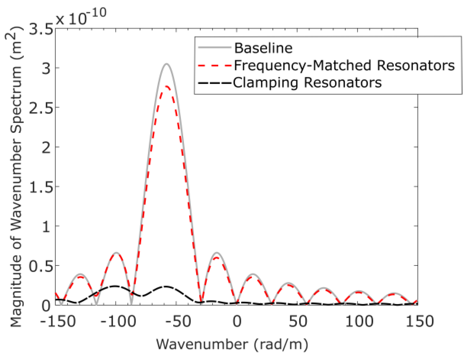
y-directions since periodic boundary conditions are applied to these edges. The clamping resonators are effective at prohibiting the propagation of much of the S0 Lamb wave, while the frequency-matched resonators are completely ineffective. The wavenumber spectrum was calculated using the complex-displacements measured from the transmitted wavefield and is shown in
Figure 8. At the wavenumber of the S0 mode we see that the frequency-matched resonators only reduce the spectrum by approximately 7%, while the clamping resonators reduce it by 90%.
5. Conclusions
Based on Williams et al.’s [
7] identification of the clamping phenomenon, we sought to investigate whether the concept’s applicability could be extended to S0 Lamb wave modes. Two approaches for designing a resonator were used based on the concepts discussed by Williams et al. These approaches resulted in the frequency-matched resonators and the clamping resonators (based on the clamping concept). The clamping resonators performed well by decreasing the amplitude of the transmitted wave by about 75%. When measuring the reflection from the clamping resonators, 62% of the incident wave was found to be reflected. The reason these two percentages do not equal each other is provisionally attributed to scattering from the resonator array and beam spread. In comparison, the frequency-matched resonators did not reduce the S0 Lamb wave amplitude. While the results for the clamping resonators used in these experiments are limited to the S0 Lamb mode at 50 kHz, these results and those of Williams et al. suggest that by designing a resonator based on the concept of clamping the waveguide, a metamaterial capable of prohibiting the propagation of a low-frequency A0 or S0 Lamb wave is possible. This also suggests that these resonators could be mode-specific by using different resonator designs for each mode. Moreover, a more detailed description of the basis for the concepts used to design the clamping resonators will be provided along with the associated theoretical modeling effort, which is still ongoing. Future work will focus on the frequency stop-bandwidth.
Author Contributions
Conceptualization, P.S., C.L. and C.H.; investigation, C.H.; writing—original draft preparation, C.H.; writing—review and editing, C.H., C.L. and P.S.; supervision, C.L.; project administration, P.S.; funding acquisition, P.S.
Funding
This research was funded by a seed grant from the College of Engineering at The Pennsylvania State University, “Engineering a giant metamaterial: a band-stop seismic/blast filter to shield critical civil infrastructure”.
Conflicts of Interest
The authors declare no conflict of interest.
References
- Pendry, J.B. Negative refraction makes a perfect lens. Phys. Rev. 2000, 85, 3966–3969. [Google Scholar] [CrossRef] [PubMed]
- Cubukcu, E.; Aydin, K.; Ozbay, E.; Foteinopoulou, S.; Soukoulis, C.M. Negative refraction by photonic crystals. Nature 2003, 423, 604–606. [Google Scholar] [CrossRef] [PubMed]
- Schurig, D.; Mock, J.J.; Justice, B.J.; Cummer, S.A.; Pendry, J.B.; Starr, A.F.; Smith, D.R. Metamaterial electromagnetic cloak at microwave frequencies. Science 2006, 314, 977–980. [Google Scholar] [CrossRef] [PubMed]
- Norris, A.N.; Shuvalov, A.L. Elastic cloaking theory. Wave Motion 2011, 48, 525–538. [Google Scholar] [CrossRef] [Green Version]
- Farhat, M.; Guenneau, S.; Enoch, S. Ultrabroadband elastic cloaking in thin plates. Phys. Rev. Lett. 2009, 103, 1–4. [Google Scholar] [CrossRef] [PubMed]
- Stenger, N.; Wilhelm, M.; Wegener, M. Experiments on elastic cloaking in thin plates. Phys. Rev. Lett. 2012, 108, 1–5. [Google Scholar] [CrossRef] [PubMed]
- Deymier, P.A. (Ed.) Acoustic Metamaterials and Phononic Crystals; Springer: Berlin, Germany, 2009. [Google Scholar]
- Liu, Z.; Zhang, X.; Mao, Y.; Zhu, Y.Y.; Yang, Z.; Chan, C.T.; Sheng, P. Locally resonant sonic materials. Science 2000, 289, 1734–1736. [Google Scholar] [CrossRef] [PubMed]
- Bilal, O.R.; Hussein, M.I. Trampoline metamaterial: Local resonance enhancement by springboards. Appl. Phys. Lett. 2013, 103, 111901. [Google Scholar] [CrossRef]
- Wu, T.C.; Wu, T.T.; Hsu, J.C. Waveguiding and frequency selection of lamb waves in a plate with a periodic stubbed surface. Phys. Rev. B 2009, 79. [Google Scholar] [CrossRef]
- Rupin, M.; Roux, P. A multi-wave elastic metamaterial based on degenerate local resonances. J. Acoust. Soc. Am. Express Lett. 2017, 142, EL75–EL81. [Google Scholar] [CrossRef] [PubMed]
- Li, Y.; Zhu, L.; Chen, T. Plate-type elastic metamaterials for low-frequency broadband elastic wave attenuation. Ultrasonics 2017, 73, 34–42. [Google Scholar] [CrossRef] [PubMed]
- Zhao, J.; Bonello, B.; Boyko, O. Focusing of the lowest-order antisymmetric lamb mode behind a gradient-index acoustic metalens with local resonators. Phys. Rev. B 2016, 93, 174306. [Google Scholar] [CrossRef]
- Rupin, M.; Lemoult, F.; Lerosey, G.; Roux, P. Experimental demonstration of ordered and disordered multiresonant metamaterials for lamb waves. Phys. Rev. Lett. 2014, 112, 234301. [Google Scholar] [CrossRef] [PubMed]
- Williams, E.G.; Roux, P.; Rupin, M.; Kuperman, W. Theory of multiresonant metamaterials for A0 lamb waves. Phys. Rev. B 2015, 91, 104307. [Google Scholar] [CrossRef]
- Alleyne, D.N.; Cawley, P. The interaction of lamb waves with defects. IEEE Trans. Ultrason. Ferroelectr. Freq. Control 1992, 39, 381–397. [Google Scholar] [CrossRef] [PubMed]
- Chillara, V.K.; Ren, B.; Lissenden, C.J. Guided wave mode selection for inhomogeneous elastic waveguides using frequency domain finite element approach. Ultrasonics 2016, 67, 199–211. [Google Scholar] [CrossRef] [PubMed] [Green Version]
- Hsu, J. Low-frequency forbidden band in phononic crystal plates with Helmholtz resonators. Jpn. J. Appl. Phys. 2011, 50. [Google Scholar] [CrossRef]
© 2019 by the authors. Licensee MDPI, Basel, Switzerland. This article is an open access article distributed under the terms and conditions of the Creative Commons Attribution (CC BY) license (http://creativecommons.org/licenses/by/4.0/).


