1. Introduction
Display devices, such as flexible OLED, micro LED, electronic papers, RFID sensors, solar panels and other electronic elements can be mass-produced in a continuous manner similar to newspapers. Thus, the low-cost mass-production of printed electronics technology is attracting considerable attention [
1,
2]. In particular, since display devices are composed of fine patterns with features ranging in size from a few μm to tens of μm, the roller must have a vibration amplitude smaller than this feature size. Ideally, the vibration amplitude should remain within a few μm. The vibration of the roller and the application of an ever force during printing are some of the most important factors directly affecting the printing accuracy. Therefore, the roller used for printing requires extremely precise printing surface processing and low rotational vibration. Commonly used printing machines for producing sub-micron patterns include roll-based nanoimprinting and reverse offset printing. In addition, since printing forces significantly affect the patterning mechanism and printing quality [
3,
4], printing machines for producing sub-micron patterns must have high-precision printing force control and a uniform printing force. For multi-step continuous roll-to-roll printing technology, the tension control of the web [
5], the roll of paper used in offset printing, using the roller and longitudinal displacement control are also important to reduce printing errors [
6]. Furthermore, the implementation of proper roller alignment is one of the most important factors in achieving high printing precision and a uniform printing force.
In general, rollers are supported by ball bearings. In the case of printed electronics equipment, the performance improvement and commercialization of printed electronics elements are hindered by the poor rotation accuracy or difficulties during the roller alignment process. Most printing equipment under research/development uses rollers with ball bearings. Ball bearings exhibit significant mechanical wobble, which produces rotational vibrations with at least 10–20 μm of displacement owing to non-uniform stiffness and clearance [
7]. In addition, rollers tend to shift during roll-to-roll printing, which causes misalignment of the printing rollers such that disassembly and re-assembly of the printing rollers is required during the production process. Due to this, it is extremely difficult and time-consuming to implement reliable precision printing. A non-uniform force distribution on the printing surface causes periodic errors due to the printing force, and may cause serious printing defects such as nanoimprinting, microcontact printing, and offset printing [
8,
9,
10,
11,
12]. The printing force applied by rollers must be uniform to improve the printing quality. For this, many additional devices are required, including various force and position sensors, pneumatic or hydraulic actuators, linear motors, and voice coil motors, which make the structure of the printing equipment complicated and more expensive while still requiring periodic re-calibration [
13].
Magnetic bearings cause constant bearing stiffness with no friction because they support rollers in a non-contact way, while controlling the magnetic force [
14]. This makes the rotational vibration of the roller very small. In addition, since the positions of both ends of the roller can be arbitrarily and easily changed within the air gaps between the shaft core and the electromagnets of the magnetic bearings, it is possible to automatically align the roller so that the printing forces at both ends of the roller can act uniformly. Active magnetic bearings have been used for a wide range of applications including rotors [
15], turbo blowers [
16], control moment gyroscopes [
17], gears [
18], and for machining [
19]. Existing magnetic bearing rotational machinery focus on the performance of rotating shafts during transmission of a torque, but no study has been done on the use of magnetic bearings to transmit a force as would be required of rollers. Furthermore, the surveyed literature does not include any function for self-aligning rollers that could significantly increase the printing performance for printed electronics.
In this study, a concept for a roller with force feedback for self-alignment making use of magnetic bearings to adjust and align the printing forces without re-assembly was designed and fabricated for precision printing. Its basic performance was tested, and the automatic alignment function was implemented and verified. The measured rotation vibration of this system under a lateral load was measured to be much less than existing rollers with ball bearings. The fine displacement movement performance of the roller using the position control of the magnetic bearings was examined, and the automatic alignment performance was experimentally verified. This study proposes the applicability of a new type of roller to precision printing equipment.
2. Automatic Alignment System Using Magnetic Bearings
For roll-to-roll or roll-to-plate type printing, alignment between the roller and printing surface is required for uniform printing quality. The alignment degree of a roller can be defined as the mechanical parallelism between the roller and printing surface or the uniformity of the printing force at both ends of the roller. For rollers with typical ball bearings, repetitive measurement, disassembly and re-assembly processes are required to adequately align the roller and printing section. In addition, during printing, additional driving devices are required to apply uniform printing forces to both ends of the roller. However, the roller can move freely within the air-gap range and the printing force at each end of the roller can be controlled when magnetic bearings are used as the radial bearings at both ends of the roller. Therefore, the printing forces at both ends of the roller can be controlled to apply a uniform pressure. Furthermore, it is possible to implement the automatic alignment function of the roller by using this characteristic.
2.1. Magnetic Bearing System Configuration
Magnetic bearings can measure and control the position of the rotor using electromagnets, sensors, and control systems.
Figure 1 shows the schematic diagram of the magnetic bearing control system. The position of the shaft within the air gap is measured using the gap sensors placed in the x and y directions. The magnetic bearing controller adjusts the position of the shaft core by controlling the input current of the magnetic bearing coil supplied through the current driver. The magnetic bearing controller consists of a proportional-integral-derivative (PID) controller with a sampling frequency of 10 kHz, a lead compensator, and a low-pass filter. The PID gain was optimized to stably levitate the rotor and secure a phase margin of more than 20°.
2.2. Principles of the Automatic Alignment System Using Magnetic Bearings
Figure 2 shows the testing setup for assessing the automatic alignment performance of the precision roller for printing. Radial magnetic bearings capable of controlling the radial position and force were installed at both ends of the roller, and a thrust magnetic bearing was placed at the right end of the roller to control the axial movement. Inside the radial magnetic bearings, gap sensors were attached in the x-axis and y-axis directions to measure the displacement of the rotor in real time. Through the feedback of the gap sensors on the measured roller displacement, the position of the roller inside the air gap was controlled. The roller proposed in this study can move up to ±0.2 mm in the radial direction from the center of the radial magnetic bearings and the force and position of each of the left and right magnetic bearings can be controlled. The position of the radial bearings can be used to adjust the force exerted by the roller and the load cells provide force feedback of the contact force and alignment of the roller with respect to the element the roller is in contact with.
Figure 3 is a conceptual diagram of the automatic alignment of the roller and shows the definition of alignment used in this paper. If the printing forces are the same, it is assumed that alignment is achieved.
3. Design of Magnetic Bearing and Roller System
Figure 4 shows the configuration of the precision roller system with magnetic bearings. The radial magnetic bearings applied to the precision roller for printing must be able to support the printing force as well as the mass of the roller, because the mass of the roller acts as a radial load. The mass of the roller is 30 kg and the maximum printing force applied to the roller during printing was set to 300 N. Therefore, the magnetic bearings at must be capable of generating a force of at least 600 N. Based on this, the radial magnetic bearings were designed to generate a force each exceeding 300 N. In the case of the axial force, the thrust generated between the core and rotor magnet in the motor and the axial component of the printing force caused by the vibration and misalignment occurring during the rotation of the roller act as axial disturbances. Since these forces are not large, the required force of the thrust magnetic bearing was set to 100 N. The roller, rotor of the motor, roller printing section, and shaft core were designed to be integrated as one part for ease of control and complete levitation. The design parameters of the radial and axial magnetic bearings were selected based on the magnetic circuit and the magnetic force equation, and they were examined using Maxwell, a finite element electromagnetic field analysis software program [
20,
21]. The dimensions of the magnetic bearings were selected based on the roller used for the test, but these dimensions may need to be increased depending on the specific application and roller used because larger bearings will be required to support heavier industrial rollers. This process is omitted from this paper for brevity. The air gap of ±0.2 mm in which the roller can move was designed to implement the automatic alignment function of the roller. This movement range is sufficient for most production processes where the adjustment is fairly small, but the current or the magnetic bearing size might need to be increased to generate the same magnetic force for larger movement ranges. The specifications of the precision roller and magnetic bearings proposed in this study are listed in
Table 1.
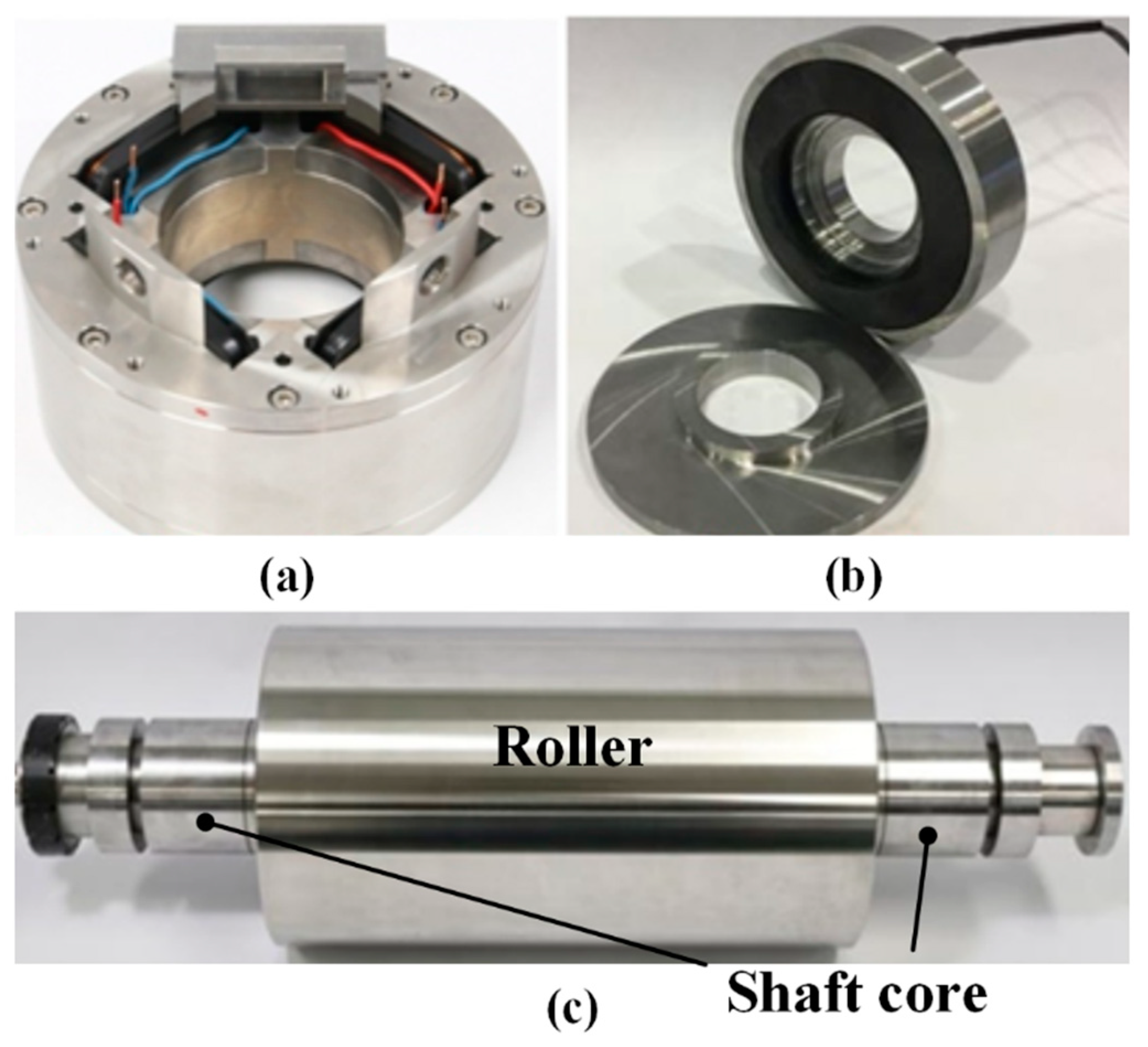
The prototypes of the magnetic bearings and precision roller equipment for printing were fabricated according to the design parameters shown previously.
Figure 5a,b shows the fabricated radial and thrust magnetic bearings, and
Figure 5c presents the precision roller. For roller rotation, a direct drive motor (TBMS-12913, Kollmorgen, Radford, VA, United States) was used.
4. Basic Performance Test of Precision Roller with Magnetic Bearings
The basic performance of the actuator to produce minimal vibration when subjected to a lateral load and to produce step-wise increase in lateral forces was verified. To implement automatic alignment on the rollers, good performance of these two characteristics is essential.
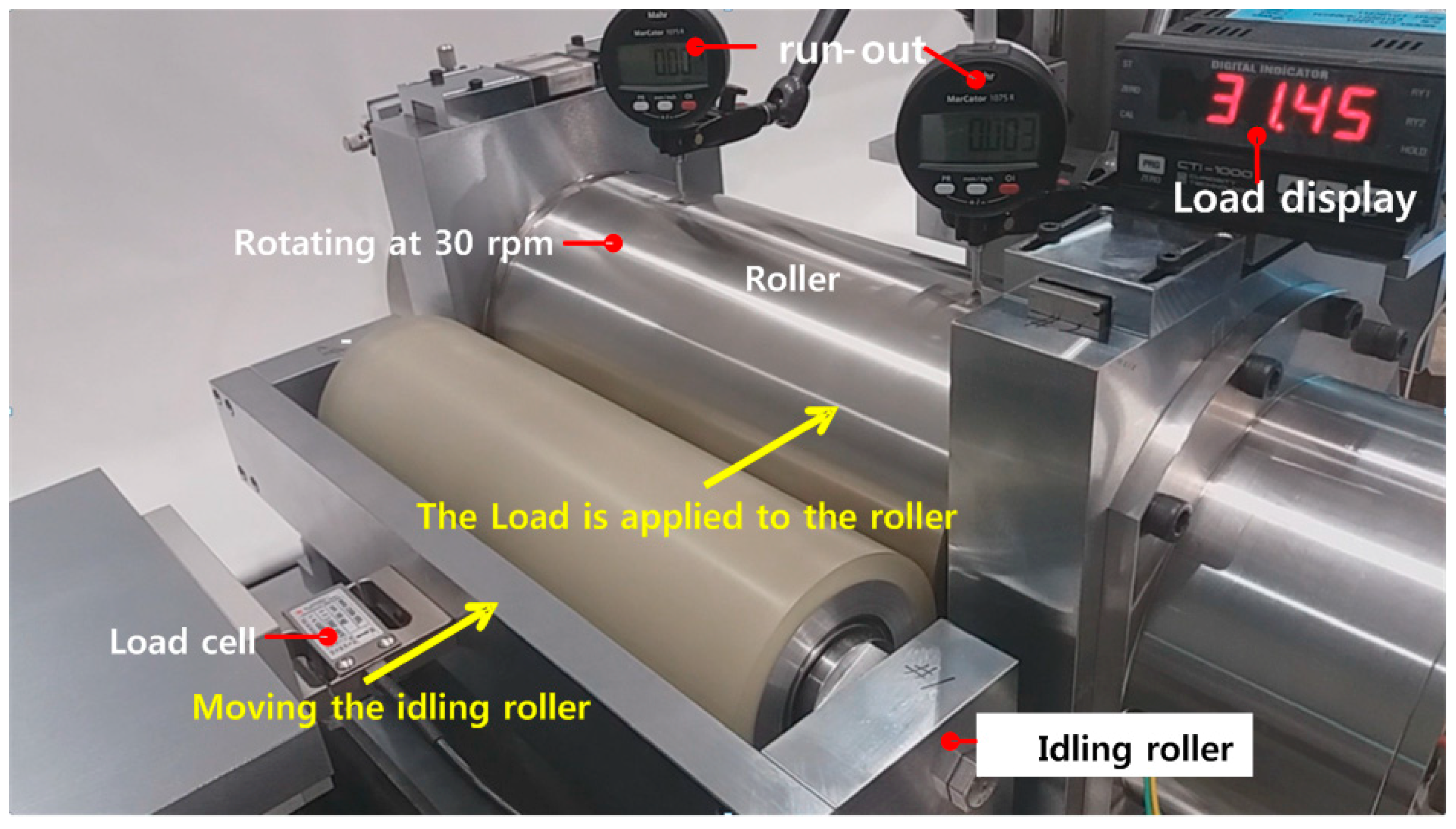
Figure 6 shows the conceptual diagram of the roll-to-roll load condition test used to evaluate the basic performance of the actuator, and
Figure 7 illustrates the experimental setup constructed based on the diagram where the idle roller has a diameter of 100 mm.
4.1. Vibration Performance of Roller under Radial Loads
A load was applied through the idle roller onto the printing roller and its value was measured using a load cell attached to the fixture of the idle roller.
Figure 8 shows the results of measuring the vibration amount of the roller depending on the load condition of the roller using the gap sensors of the left and right radial magnetic bearings. The vibration was first measured without contact with the idle roller under stop condition and at 30 rev/min (
Figure 8a,b). The maximum vibration measured under the stop condition was approximately 2.2 μm (peak-to-peak) while the maximum vibration at 30 rev/min was approximately 3.6 μm (peak-to-peak). Next, the roller was tested at 30 rev/min under a 300 N lateral load from the idle roller which rotates at 51 rev/min or 0.85 Hz (
Figure 8c). The maximum vibration measured in the 30 rev/min rotation and 300-N maximum load condition was approximately 4.6 μm (peak-to-peak). In this case, the vibration component of the rotation frequency of the idle roller (0.85 Hz) was found to be the largest source of vibration. These vibrations are originated from all components of the system including the vibration caused by the magnetic levitation of the roller, the roundness error of the shaft core, vibration of the driving motor or from the idle roller, the mass unbalance of the roller and from sensor noise.
During rotation, a larger harmonic vibration was measured at the left bearing than at the right bearing. This appears to be because of the impact of the torque ripple in the motor located on the left end. The frequency of this vibration was 78 Hz, which is the 156th harmonic component corresponding to the least common multiple of 12-pole and 39-slot. It was confirmed that the roller with magnetic bearings was capable of a rotational vibration performance of less than 4.6 μm (peak-to-peak) even when applying a large lateral force of 300 N at a rotational speed of 30 rev/min.
4.2. Step Movement Control Performance of Roller
Another function that the roller must meet is the ability to accurately execute step movement position control to be able to calibrate the roller without disassembly of the entire system. The next section shows the performance of the roller to execute step movements of different heights in order to evaluate in advance how small the resolution of the step movement that the roller is able to perform.
The magnetic bearings perform feedback control to constantly position the shaft core at the reference position, which is the center of the magnetic bearing stator core, by measuring the error between the actual position of the shaft core and the reference position and compensating for the error. The reference positions of the left and right radial magnetic bearings are moved in the radial direction to perform a step movement. The resolution and settling time for step movements of 10 and 1 μm was measured with step movements being executed at constant intervals of 2 s. After five steps, the reference positions were moved back to the origin in five steps.
In the 10 μm movement test, an overshoot of approximately 20% occurred after the movement with a rising time of 0.047 s, and the movement to the reference position was performed with a 3% settling time of 0.47 s (
Figure 9a). Position control with a resolution of approximately 1 μm was also confirmed to be possible using magnetic bearings, which would be useful for the superimposed printing of precise patterns (
Figure 9b).
6. Conclusions
In this study, the automatic alignment of the precision roller for printing was implemented using the ability of magnetic bearings to move the position of the roller within the air-gap range. A precision roller for printing capable of ±0.2 mm movement and magnetic bearings were designed and fabricated. When the precision roller contacted the alignment reference surface, the contact forces at both ends of the roller could be measured using load cells. An automatic alignment produce was developed by using the forces measured by the load cells as feedback. The improved alignment was implemented by applying two-step displacements, and the difference in the contact forces between each end was within 0.3 N. Vibrations of less than approximately 2 μm peak-to-peak was confirmed under the no-load condition and of less than approximately 5 μm peak-to-peak was observed under a rotation speed of 30 rev/min and a load of 300 N. This vibration is very small compared to the vibration of 10–100 μm peak-to-peak of conventional printing rollers supported by ball bearings [
13].
The proposed system is the first magnetic bearing system designed to produce a controllable lateral load onto an external object, making it superior in terms of energy, time and quality to existing systems. If the proposed magnetic bearing roller system is used, it is expected that the disassembly–assembly process for the realignment of the assembled roller will not be necessary. In addition, the proposed system will also provide significant benefits in terms of the cost and volume because additional actuators required for uniform printing force control on both ends of the roller will not be necessary. The lower friction of the bearings will also make the system more energy efficient and prevent printing failures, which makes the system greener. In the future, the vibration performance of the roller will be further improved by applying additional control algorithms against loads and disturbances that may occur in printing equipment, such as printed electronics equipment. In addition, improved control algorithms will be used to automate the fine adjustments near the setpoint.


