1. Introduction
With the rapid development of virtual reality technology, mixed reality technology, and human–computer interaction technology, an increasing number of businesses are working from various angles to realize erasure animations in mixed reality so that their users’ participations can be improved. Some examples are Fruit Ninja and The Swords. In these systems, limits exist in the number of face-to-face participants and the unnatural interactive devices. How to realize rich somatosensory interactive erasure animations for a large group of face-to-face participants by some popular interactive devices has great influence on the participations.
The technologies of image matting and interactive erasing are working to develop users’ participations in erasure animations. Existing image matting methods are mainly used for two-dimensional (2D) scenes and their mask images and background images are all 2D data. They do not support customizations of three-dimensional (3D) scenes [
1,
2]. Some 3D simulation software systems, such as Unity3D and Unreal Engine 4, use their powerful shader functions to perform texture transparency blending on the image which contains the information of erasure shapes and background scenes, and thus reveal the scenes. The erasure can be performed in every position. However, the visualization of multiple erasure actions simultaneously requires to create and load multiple shaders, which is very time-consuming. Therefore, they are not suitable for a larger number of participants. In the field of interactive erasing technology, some sensor-based, and vision-based gesture recognition methods are used for interactions [
3,
4], for example, virtual reality glasses, Kinect, cameras. Some of them are not easy in implementation and some of them suffer from serious occlusion of a larger number participants.
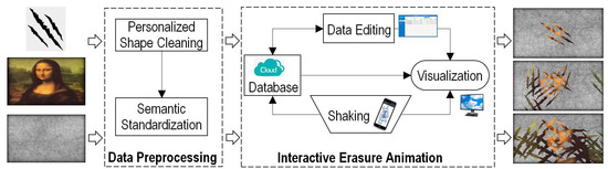
To tackle the aforementioned challenges, we design a system to realize interactive and personalized erasure animations by using mobile terminals, a shared display terminal and a database server. The system is implemented by a data preprocessing module and an interactive erasure animation module (
Figure 1). The data preprocessing module is mainly responsible for preprocessing the input erasure shape data, including cleaning the personalized shape data and semantic standardizations. The interactive erasure animation module consists of three parts: shaking mobile terminals, visualization of the erasure animations in the shared display terminal, and dynamic and personalized data editing in the database server. In our system, users shake their mobile terminals continuously and simultaneously with their hands, and their valid shaking data are captured and saved in the database server. Then the shared display terminal accesses the database server and shows visualizations of real-time erasure animations according to the data. Note that the system can only show a continuous animation for many shakings: one valid shaking occurs when a user shakes his mobile terminal, then the shared display shows an erasure shape; another valid shaking occurs when another user shakes his mobile terminal, then the shared display shows two erasure shapes; more valid shakings occur and then the shared display shows more erasure shapes.
The main contributions of our system are as follows:
We introduce a novel interactive erasure animation system based on a shared display terminal and mobile terminals (mobile phone/tablet computer), the implementation of which is very easy for a larger number of participants.
In our system, the shared display terminal can respond to a larger number of shaking actions from participants in real time and show an immersive and somatosensory erasure animation, the erasure shapes which are highly consistent with the participants’ shaking actions (position, travel distance, angle, etc.).
Our system supports real-time personalized erasure animations. The erasure shape, mask data, scene data, and so on can be customized on our backend management platform. The scale, rotation, and translation of each shape are personalized and determined by the corresponding shaking action.
2. Related Work
Our work has a cross-section of research in the fields of image matting and interaction technique. In this section, we first briefly review the previous work in image matting and then introduce the interaction in mixed reality.
2.1. Image Matting
With the development of digital multimedia technologies, image matting has gained increasing interest from both academic and industrial communities. Existing image matting methods are simply divided into three types: sampling-based methods, propagation-based methods, and hybrid methods that combine the sampling-based methods and propagation-based methods.
The basic idea of sampling-based methods [
5,
6,
7] is as follows: It is assumed that the pixels of an unknown area can be estimated according to the nearby foreground color and background color. The value of the transparency can be calculated using these known sample pixels, and thus the pixels of the unknown area are partitioned. For example, the probability and statistics method [
7], the Bayes image matting algorithm [
5]. The quality of image matting yielded by the sampling-based method depends heavily on the transparency of pixels of the unknown area. Propagation-based methods [
8,
9,
10,
11,
12,
13] make assumptions based on the statistical properties of the image and describe the relationship between neighboring pixels based on color, spatial position, and so on. Closed-form matting [
10], Poisson matting [
13], and KNN matting [
14] are some famous propagation-based methods. To better combine the advantages of the above two methods, some researchers have proposed hybrid method that combines the sampling-based and propagation-based methods [
15,
16,
17], such as the shared-matting method [
15], the global matting method [
16], and robust mapping method [
17].
The purpose of image matting is to precisely extract the foreground objects with arbitrary shapes from an image or a video frame [
6]. Both of their foreground data and background data are 2D raster data. They cannot be used for 3D interactive erasure animations, which can provide immersive and somatosensory animations.
2.2. Interaction in Mixed Reality
Mixed reality content can be interacted with via different devices, such as mobile terminals, virtual reality glasses, and Kinect [
18]. Simon et al. [
4] introduced an interaction paradigm for co-located collaboration in large projection-based display systems. Their system provides a shared experience and collaboration for a large number of users by handling the same shared display terminal, which inspires us to deal with large number of participants. On the one hand, the system was designed for tracking controls in the shared display terminal and can not be used for interactive erasures. On the other hand, our interactive erasures can be realized by hand gestures, which play an important role in our day to day communication.
2.2.1. Hand Gesture Recognition
Hand gestures play a natural and intuitive communication model for all human interactive erasures. The ability of a computer or any processing system to understand the meaning of these gestures is referred to the hand gesture recognitions. According to the difference of input devices, there are two methods for hand gesture recognitions: the sensor-based method and the vision-based method.
In the sensor-based method, a user wears a sensor terminal or a colored glove, which serves as an interface to communicate with the computer. The method makes it easy to collect hand movement data and can give accurate results. However, it is cumbersome and unnatural. It hinders the ease and naturalness with which the user can interact with the computer [
4,
19]. So, the key is to get accurate hand gesture results by some light and portable terminals. The vision-based method overcomes the drawback of the sensor-based method as it serves as a natural means of interaction [
19]. In this method, the movement of the hand is recorded by video cameras. This input video is decomposed into a set of features [
20]. The method adopts computer vision and machine learning algorithms for recognizing the features. However, obtaining highly accurate results is a challenging task for the vision-based method [
21], especially when large number of participants and serious occlusions occur.
Here we introduce a database server to bridge the mobile terminals and the shared display terminal to realize interactive erasure animations, the implementation of which is very easy for a larger number of participants. There are no occlusion problems in our system.
2.2.2. 3D Animation
The key problem in the mixed reality interaction is the animation efficiency. Researchers in the fields of computer graphics have proposed lots of methods to improve animation efficiency, such as point-based method, image-based method, and the Level Of Detail (LOD) method [
22,
23,
24]. The LOD method [
22] decreases the complexity of a 3D model representation as it moves away from the viewer. The reduced visual quality of the model is often unnoticed because of the small effect on object appear.
In this study, we combined the ideas of image matting, LOD method, and the hand gesture interaction to realize the interactive erasure animations.
3. Data Preprocessing
Data preprocessing refers to preprocessing the erasure shape data to reduce the computing complexity during the following erase animations.
In our system, the input erasure shape data is image data. The purpose of data preprocessing is to extract the erasure shape from the image data and semanticize it, so that it can be used conveniently in erasure animations. The input image data which contains the erasure shape data must be a noise-free grayscale image (Two colors in the image, one is the foreground color and the other is the background color), which is created by an image matting method [
6].
We transform the above erasure shape data to the vector data with a semantic standardization to make a template for the subsequent real-time animation process. The process mainly includes the following three steps (
Figure 2).
3.1. Vectorization of the Erasure Shape Data
The erasure shape is usually irregular, and it may even have multiple connection graphs. Inspired by the idea of the scan line algorithm, we obtain the vector data of the erasure shape boundaries from the image raster data through a row-by-row scanning process to realize the vectorization of the image data. The process consists of three steps: finding the intersections, sorting the intersections, and pairing the intersections.
Finding the intersections: The scan lines are intersected with the edges of the erasure shape during row-by-row scanning and then the coordinates of each intersection points can be calculated (
Figure 3).
Sorting the intersections: We sort the intersection points according to their x-coordinates.
Pairing the intersections: We pair the sorted points in the following way according to their x-coordinates: 1st and 2nd, 3rd, and 4th, and so on. Each pair of intersection points represents the left and right boundary of the erasure shape.
We then obtain a vector data set
represented by a 2D coordinate sequence to describe the boundary of the erase shape:
Here represents the left and right boundary of the erasure shape. t is the number of scan lines, represents the number of intersection points between the i-th scan line and the boundary of the erasure shape.
Let
, then
Let
be the
i-th line. It is easy to prove that the number of elements in each line in Equation (
1) is different, that is,
. The reason is that the erasure shape is irregularity and complexity (for example, in
Figure 3, the number of elements obtained by the scan line a is 4, and the number is 2 by the scan line b).
To facilitate computations of the subsequent operations, it is necessary to use a matrix to depict .
3.2. Matrixing of the Vector Data
Let the matrix of
be
, then
For , if , let .
It is easy to see that
and
(
) are never the left boundary of a connection graph (
Figure 3). In order to realize an efficient searching in animations, we use position-shifting operations to ensure that
and
(
) are the left boundary of one connection graph. Algorithm 1 is as follows:
| Algorithm 1: Position-shifting operations for P. |
|
3.3. Affine Transformation of the Matrix Data
It is difficult to use the above shape data to realize an erasure animation. The reasons are as follows:
The area of the erasure shape is larger than the area of the shared display terminal. We have to shrink the size of the shape to make sure that it can be drawn on the shared display terminal.
The coordinate values of the erasure shape are too large/small. We have to translate all of the coordinates of the erasure shape to make sure it can be drawn on the shared display terminal.
Here we use the following affine transformations to solve above problems:
Here
A is a
diagonal matrix, in which principle diagonal elements are
k.
k denotes the scaling coefficient:
Here w and h are the length and width of the shared display terminal, respectively. is constant and . If , the area of the erasure shape is nearly same as the area of the shared display terminal. The area of the erasure shape is smaller than the area of the shared display terminal if the value of is smaller.
Translating transformation:
Here
B is a translation matrix,
Here . is the translation distance on the x-coordinate, is the translation distance on the y-coordinate, , and .
After the above translating transformation process, the center position of the erasure shape is near the center of the shared display terminal. is the template of the erasure shape for the subsequent real-time animation process.
4. Interactive Erasure Animation
In this section, we introduce an interactive erasure animation process based on the above- mentioned erasure shape data.
To conduct a rich somatosensory interactive erasure animation process for all participants, one shared display terminal is used for all of them. These participants continuously and simultaneously shake their mobile terminals with their hands. Note that all popular mobile terminals, such as iphone mobile phones, android based mobile phones, tablet computers, can be directly used in our system. Then our system shows visualizations of real-time erasure animations on the shared display terminal (for example, a large screen), the shapes of which are highly consistent with the participants’ shaking actions: the rotation angle of the erasure shape is consistent with the angle that the mobile terminal is turned during shaking, and the size of the erasure shape is proportional to the displacement of the mobile terminal, etc.
Now we have to process multiple sets of shaking data in parallel in the shared display terminal, in which we also have to do time-consuming erasure animations. There are no ready sensors to capture the shaking data and transmit them to the shared display terminal. The vision-based method [
19] cannot be used because there are serious occlusions among participants. Here we introduce a database server to bridge the mobile terminals and the shared display terminal. Participants firstly connect their mobile terminals to the database server. The database server then captures and saves their shaking data through the accelerometers of their mobile terminals. The shared display terminal accesses the database server in real time to show visualizations of the interactive erasure animations.
From a user’s point, there are three steps to realize an interactive erasure animation process: shaking mobile terminals, visualization of the erasure animations in the shared display terminal, and dynamic and personalized data editing in the database server.
4.1. Shaking the Mobile Terminal
Participants can apply the interaction permission via mobile terminals by submitting their personal information to the database server through scanning a QR code. After their permissions are successfully obtained, connections between their mobile terminals and the database server are built. They shake their mobile terminals using their hands. The database server captures all of their shaking actions through the accelerometers of their mobile terminals in real time and then judges the validity of the shaking actions. The valid shaking data (shaking angles, shaking amplitudes, and shaking positions) are saved into the database for erasure animations (
Figure 4).
A valid shaking action is defined as follows:
The time interval between two adjacent shaking actions for a user is larger than the interval threshold T_threshold. In our system, T_threshold = 0.1s.
The shaking speed is larger than the speed threshold v_threshold. In our system, v_threshold = 2 m/s.
Algorithm 2, about how to capture the shaking action of a user and judge its validity, is as follows:
| Algorithm 2: How to capture the shaking action of a user and judge its validity. |
|
Here curTime is the current time and lastTime is the starting time of the last valid shaking action. (x, y, z) and (last_x, last_y, last_z) are the coordinates of the center of gravity of the mobile template at the moment of curTime and lastTime. represents the amplitude of the shaking action. returns the angle value of the 2D vector, which is the angle value of the vector (x-last_ x, z-last_ z). We use to save the valid shaking action data into the database. The coordinate system of the above coordinates is described as follows:
The origin is the central point of the display template.
The x-axis direction and the z-axis direction are parallel to the horizontal direction and vertical direction of the display template, respectively.
The coordinate system complies with the right-hand rule.
4.2. Visualization of the Erasure Animations
Our system accesses the shaking data from the database server and shows a real-time visualization of the erasure animations on the shared display terminal.
In our system, we use the orthographic projection theory [
25] and the LOD method [
22] to realize the visualization of the erasure animations. Specifically, we draw the environment in the direction of the observer’s sight in the 3D space created by orthographic projection and then draw a mask image in front of it. In the erasure animation, let the alpha channel of the erasure area be 0 (i.e., completely transparent), and the alpha channel of the rest area be 1 (i.e., completely opaque). The erasure area is the set of erasure shapes, which is created by all users participating in the interaction. Let the direction of the observer’s sight in the 3D space be the positive direction of the z-axis and the position where the mask image draws be
.
Let the total number of valid shaking actions be N in the database and the projection coordinates of the shaking position of the kth valid shaking action in N be . Algorithm 3 for the process of calculating the erasure area R is as follows:
| Algorithm 3: The process of calculating the erasure area R. |
|
Here
is the shaking amplitude, which is calculated in
Section 4.1.
is the amplitude threshold, which is 0.2 m in our system.
is a positive integer and is determined by the distance between the shared display terminal and the mobile terminal.
is the shaking angle, which is calculated in
Section 4.1.
and
are the first-order Taylor expansions of
and
, respectively.
is the boundary of the erasure shape, which is calculated in
Section 3.
represents the polygon defined by coordinates
, and
.
4.3. Dynamic and Personalized Data Editing
A lot of data have to be used in each erasure animation frame in our system, such as scenes, mask data, templates of erasure shapes, users, shaking data. We save the data in the database server for better management. We develop a backend management platform to manage and customize these data. In our system, we can customize the following data in real time: scene data, mask image, erasure shape, erasure sound, and the interaction permissions of each user, and so on.
The scene data can be 2D vector data, images, videos, and 3D scenarios. We can modify the scene data information in real time, and the shared display terminal responds to the data change in real time. The mask image is an image. All common image file formats (JPG, PNG, BMP, TIFF, etc.) can be used in our system directly. The erasure shape data are obtained in
Section 3. We can change the erasure shape by modifying the erasure template data. If we choose the erasure template that has been made in
Section 3, the shared display terminal responds to the data change instantly. If we choose a new erasure shape, we should firstly create the erasure template according to the method described in
Section 3. The erasure sound shows the sound in the shared display terminal when a valid shaking action occurs in our system. When the erasure sound is changed, the shared display terminal will show the new sound when a user creates a valid shaking action. We can also decide the interaction permissions of each user. The shaking action of users without the interaction permission will not yield any erasure animation on the shared display terminal.
5. Results
We introduce a system to realize interactive and personalized erasure animations. In our experiments, a large screen was shared by users. These users stood (or sat down) in front of the screen. There are serious occlusions among these users. They applied the interaction permission firstly and then shook their smartphones using their hands. What follows are results about kinds of personalization/interaction and performance analysis.
5.1. Kinds of Personalization and Interaction
We can customize erasure shapes, scene data, and so on. In addition, there are high interactions between the shaking actions of users and the visualization of erasure animations. Different shaking actions introduce different erasure animations.
5.1.1. Erasure Shape
Almost all kinds of shapes can be used in our system, including single connection graphs, multiple connection graphs, convex polygons, concave polygons, etc.
Figure 5 shows some erasure animations when different shapes (including ellipse, pentagram, flag, and multi-connection concave polygon) were used (The outcome is highlighted in the
supplementary video (
http://v.qq.com/vplus/f9ca5d28f9c7c8696f356522325b0902)). Note that if the shape has been made into an erasure template, we can use it directly in erasure animations. Otherwise, we should firstly create the erasure template according to the method described in
Section 3.
5.1.2. Scene Data and Mask Image
We can update the scene data and mask image in real time in erasure animations. The scene data can be videos, 3D scenarios, 2D images, 2D vector data, etc. The file formats of mask image data can be JPG, PNG, BMP, TIFF, etc. There is no constraint for the mask image features.
Figure 6 shows some visualizations of the erasure animations with a 3D scenario.
Figure 7 shows visualizations with a video/2D image scene data and different mask image data. As shown, our system is capable of showing erasure animations no matter what types of scene data and mask image data are used, which ensures a large scope of application.
5.1.3. Erasure Animation
In
Section 4.2, we show how to realize a visualization of the erasure animations on the display terminal. One erasure shape corresponds to one valid shaking action. The position of the erasure shape for the
kth valid shaking action is
, which is obtained from the database server. The size and the angle of the erasure shape for the
kth valid shaking action are determined by
(the amplitude of the shaking action) and
(the rotation angle of the shaking action), which are also obtained from the database server.
Figure 8 shows some erasure animations with different rotation angles, different positions, different amplitudes, and different times of shaking actions. The left-most subfigure of
Figure 8 shows the erasure animation of a valid shaking action (
,
,
,
in
Section 4.2).
Figure 8a shows the erasure animation of one valid shaking action with a different rotation angle (
).
Figure 8b shows the erasure animation of one valid shaking action at a different spatial position (
).
Figure 8c shows the erasure animation of a valid shaking action with a different amplitude (
).
Figure 9 shows some snapshots of the erasure animation as the number of valid shakings increases. More valid shaking actions occur and then the shared display shows more erasures shapes. The shapes (scale, rotation, translation, and number) are highly consistent with the users’ shaking actions, which indicate natural interactions between users and the display terminal.
5.2. Performance Analysis
We evaluate the performance of our system from two parts: the efficiency of data preprocessing and the efficiency of the erasure animations. These results were collected on an Intel(R) Core 8 Xeon (TM) i7-4790 CPU with a 3.60 GHz processor and 4.0 GB of RAM.
5.2.1. Efficiency of Data Preprocessing
The efficiency of data preprocessing is determined by the size of the input image and the size of the erasure shape in the image.
Firstly, we zoomed in on a 256 × 256 image, the circumference of the erasure shape in which is 980 pixels.
Figure 10 shows the relationship between the size of the image and the total data preprocessing time. It shows that the data preprocessing time increased as the image size increases. The reason is that the size of the image affects the whole data preprocessing process, including the vectorization of the erasure shape data, the matrixing of the vector data, and the affine transformation of the matrix data. Note that the side length of the image is usually about 1000 pixels. The data preprocessing process can be completed in a matter of seconds, which is completely acceptable to users.
Secondly, we changed the circumference of an erasure shape in a 1024 × 1024 image.
Figure 11 shows the relationship between the circumference of the erasure shape and the total data preprocessing time. It shows that the data preprocessing time increased as the circumference of the erasure shape increases. The reason is that the size of the erasure shape affects the matrixing process of the vector data and the affine transformation process of the matrix data.
5.2.2. Efficiency of Erasure Animations
We showed our system in a meeting with new students to evaluate the performance of our erasure animations. There were about 1500 students and all of them had obtained the interaction permissions. They shook their mobile terminals using their hands. The largest number of valid shaking actions captured by our system is 620 in a short time interval (50 ms). Our system can respond to those actions simultaneously and present the corresponding erasure animations on the shared display terminal in real time.
We also used our system to a simulation experiment to evaluate the relationship between the number of shaking actions and the total computing time of the erasure animations. In the experiment, we used an erase shape with a perimeter of 1192 pixels. The experimental results are shown in
Figure 12. It shows that our system could respond to more than 2000 shaking actions. Note that in this experiment, we did not take into account of the duration of shaking data transmissions from mobile terminals to our database server.
6. Conclusions
We introduced a novel and easy-to-use interactive and personalized erasure animation system by using mobile terminals, a shared display terminal, and a database server for a large group of participants. We do not need to face the occlusion problems and the unnatural sensor terminals in our system. Users apply for the interaction permissions and then shake their mobile terminals. Their valid shaking actions are captured and saved in the database server of our system. The shared display terminal then shows 3D visualization of erasure animations according to the shaking actions. The experimental results show that there are natural interactions between the user and the shared display terminal. Our system can respond to more than 2000 shaking actions simultaneously and present the corresponding erasure animations on the shared display terminal in real time. In the future, we would like to introduce a continuous animation for each erasure shape to realize a richer somatosensory interactive erasure animation. We also would like to make the erasure shape consistent with the user’s shaking rather than the erasure template in our animation.


