Abstract
This study presents the improvement of energy efficiency and operating time of mini-loader vehicles by integrating the power system of internal combustion engines (ICE) and electric motors (EM). The hybrid powertrain was developed based on the belt-starter generator (BSG). The BSG system enabled us to choose optionally the ICE or the EM mode according to the power demand in different usage scenarios. The required power specifications were evaluated. The equipment in conformity with specification was then tight-stacking installed in the limited space of the mini-loader. Therefore, the mini-loader ably passes across a 770 mm width door. In the situation of consumption of the same amount of gasoline, the hybrid power mode can increase the operating time by 30 min. In addition, its power output can be satisfied to override 140 mm high short steps, cross a 300 mm trench, and climbing a 30% slope. In particular, using electricity as a power source can reduce carbon emission.
1. Introduction
Climate change-related disasters caused by the greenhouse effect, in terms both of quantity and intensity, have been increasing year on year. Therefore, disaster relief has become an important issue. In order to operate conveniently in the disaster scene, existing mini machines are with few functions and need to be improved, mainly for detecting signs of life or surveying disaster sites. However, mini-loader vehicles, which are used in agricultural operations have the potential to be refitted as multi-purpose disaster relief machines [1]. For example, the mini-loader (C85 Series, CORMIDI, U.S.) can be used as a tool vehicle for disaster relief, transporting goods, and excavation operations by consuming gasoline as fuel. The small size design not only allows it to enter a narrow space for operation, but also meets the needs of excavation and transportation of goods. In addition, a multifunctional loader (HS1100, Hinowa SpA, Nogara, Italy) is developed which allows operators to replace operation equipment quickly and easily in a single vehicle, thus meeting the needs of diverse operation situations, such as digging, transportation, cargo lifting, and cement mixing. The power chassis uses the internal combustion engine (ICE). Replacement modules are provided as tools to meet the needs of users and expands the operation category and scope of mini vehicles. Another commercial loader (CINGO, MERLO, Italy) strives to satisfy consumers’ requirements for a single vehicle with more suitable work tools, such as sweeping, watering, mowing, and snow removal. This vehicle divides the body into two parts: the power platform and tools. The power platform uses a 33 hp ICE system to allow the platform to withstand greater loads, and the tools can perform the four functions described above are also included in the tools.
These conventional mini-loader vehicles are driven by ICE, and the concept of hybrid powers has not yet been introduced. However, hybrid vehicles can reduce greenhouse gas emissions and increase the total amount of available energy [2,3,4]. In addition, there are many advantages to electrifying the loader vehicles of ICE. Several reports have revealed that improvements in the electro-hydraulic system have saved energy. Wang et al. [5] have analyzed the possible energy saving of a hybrid hydraulic excavator under different operating conditions. Bedotti et al. [6] constructed a new control mode with an excavator equipped with a load sensing hydraulic system, which saves 15% fuel. Xia et al. [7] proposed an integrated drive and energy recuperation system based on a three-chamber hydraulic cylinder. This design can save 50% energy consumption and 64% of peak power. Furthermore, the more flexible control strategy for power strain systems has enhanced energy efficiency. For example, Gong et al. [8] developed a novel electro-hydraulic control system to integrate into recovery and regeneration devices. Shen et al. [9] discussed the boom energy regeneration technology for hydraulic construction machinery. Chen et al. [10] investigated the control strategy of the power train system in the hybrid hydraulic excavators. In particular, the motor can also be served as a power generator that regenerated the potential energy and significantly enhanced energy efficiency [11,12,13,14,15].
At present, even though the designs of hybrid power machinery have been developed, which can be reviewed in academic papers [16,17,18,19], in the market, only large-scale machines have products with gas–electric hybrid power systems. The large-scale dozer (D7E, Caterpillar, Peoria, IL, USA) is equipped with a diesel–electric hybrid power system. The output of the flywheel is 238 hp and the machine has a longer operating time than general dozers. The excavator (ZH200, Hitachi, Tokyo, Japan) is equipped with a diesel–electric hybrid power system. The output of the flywheel is 154 hp and can also provide a longer operating time. Despite the fact that the hybrid power can meet the demand of green energy, the mini-loader vehicles and typical hybrid vehicles have large differences includes the structure, transmission, weight range, load, and energy consumption. The mini-loader vehicles use a hydraulic system to drive the working devices, the load varies greatly during working operation, and energy consumption characteristics are more complex. Therefore, the previous researches of typical hybrid vehicles cannot be directly applied to mini-loader vehicles.
The multifunctional mini-loader vehicle with a hybrid power system is a feasible solution for the powertrain development with higher fuel efficiency, less energy use, and emissions. However, existing commercial mini-vehicle systems are insufficient to cope with the increasingly demanding multifunctional requirements and high energy efficiency. Most importantly, when power is supplied only by the ICE, not only are the systems prone to generating a large amount of greenhouse gases, but they also cause air pollution in a confined space, which is harmful to the operators. Mini-vehicles are limited to the space requirement of the operation. Not exceeding the volume specification after incorporating the electric motor (EM), battery, and motor module is an important challenge for the machine design. Therefore, considering the need to replaceable tool functions, increase the amount of available energy, reduce greenhouse gas emissions, and create a user-friendly work environment while maintaining a certain volume requirement, the goal of this study was to design a mini-loader vehicle using gas–electric hybrid power system. The three design requirements for the multifunctional mini-loader vehicle are as follows: first, emissions from fossil fuel combustion can cause harmful pollution to the environment, humans, and even crops. Therefore, energy-saving and carbon reduction have become important indices of the power system design of vehicles. Second, with the rise of greenhouse planting and indoor agricultural planting, mini-car bodies are needed to travel through narrow entrances and operate in indoor spaces. Finally, the capabilities of this loader should be extended to disaster relief and civil engineering to clear road obstacles and climb barriers, increasing its value and usage.
2. Materials and Methods
After completing the above mention on the requirements of the vehicle system, this study concludes that there are two main mechanisms for the mini-loader vehicle. First, the power system has to be designed as a mild hybrid power system with two power sources. The considerations include the drive design, the motor, and the battery module design. Second, to reduce engine load, the system should be hydraulic. The hydraulic system is powered by electricity, which is supplied by the battery module. The hydraulic valves of each module are integrated into a hydraulic valve block to simplify the system and reduce the operation time of personnel. The tool module is initially set as a shovel and transportation tool, and the vehicle is equipped to maneuver through dozing soil and transporting soil, which can be used quickly for disaster relief. Through the establishment of replacement modules, the vehicle can be extended to other agricultural operations such as plowing and spraying. The following sections describe the design of the mobile module, hybrid power system, hydraulic system, and tool module of the vehicle.
2.1. Vehicle Mobile Module
Common locomotion modes can be classified into three categories, including wheeled type, articulated multipedal type, and track type. Wheeled vehicles are most common, with the advantages of low cost and movement noise, ease of control, and the ability of high-speed driving on flat grounds. However, the ability of vehicles to cross obstacles is limited to the size of the wheel diameter, and different sizes of tires are required to handle different road conditions. When it comes to loose sand, the driving efficiency is still not as good as track types. The articulated multipedal mechanism is extremely agile and maneuverable and mimics the complex movements of creatures, with the movement being the most unrestricted by terrains. Therefore, the brakes and sensors of this system are important components. In addition to the complicated structure and high cost, the stability of the system control is also an issue. Tracked vehicles are generally used for military and civil engineering. The advantages are small grounding pressure, good off-road performance, strong ability to cross obstacles and trenches, and relatively high load-carrying capacity. Tracked vehicles have a small minimum turning radius and have the ability to rotate in place. Compared with the two other types, tracked vehicles are more suitable for disaster relief, and therefore chosen by this study as the locomotion mode of the vehicle.
2.2. Design of the Hybrid Power System
The mild-hybrid power system is divided into two categories, the integrated starter generator (ISG) and the belt-starter generator (BSG) [20]. The ISG system has the advantages of having a fast reaction speed and a smooth motion; the disadvantage is high cost. The BSG system employs a parallel hybrid power technology that uses an EM to drive a serpentine belt to power the crankshaft of the ICE. The EM unit is installed in the position of a conventional vehicle alternator, as shown in Figure 1. This is a low-cost approach to achieving mild hybrid power functions such as the start and stop of vehicles, power assistance, and mild applications of regenerative braking. It has been valued and adopted by many car companies [21]. After evaluation, the BSG system was concluded to be more suitable for this study. In addition to the advantage of not requiring special modifications to the ICE structure, it also is of low cost. Hence, the vehicle power system is designed for conversion according to the requirements of operators, switching to the motor mode in narrow space operations to reduce the amount of exhaust in the area, accomplishing carbon reduction benefits and improving the performance of the vehicle. The system switches to the engine mode when the battery is low and uses the gearbox to output power, while the belt drives the generator to charge the battery. When a large torque output is required, the system is switched to the hybrid power mode; the torques of the ICE and the EM are combined simultaneously for high torque outputs.
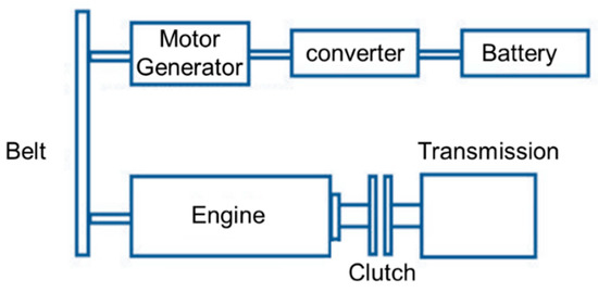
Figure 1.
Belt-starter generator structure.
Because the state-of-art charging strategy can significantly prolong the cycle-life of Li-ion battery, Li-ion batteries were chosen as electric power source/storage [22,23]. Thus, the hybrid power system of the vehicle is composed of a Li-ion battery, a hydraulic pump, a hydraulic valve, a motor/generator, a fuel engine, a transmission mechanism, and a motor controller. The Li-ion battery provides electricity to the motor and the hydraulic pump, and the hydraulic pump drives the hydraulic valve to actuate the hydraulic system. The motor provides power to start the fuel engine or to transfer power to the transmission mechanism through the belt to move the loader vehicle. When the fuel engine is actuated, the motor can also be converted to a generator to charge the Li-ion battery or to output power through the belt to the transmission mechanism to move the loader vehicle with hybrid power. The hybrid power system structure is shown in Figure 2.
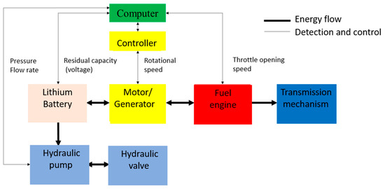
Figure 2.
Hybrid power system design.
2.2.1. Design of the Drive Specifications
In addition to the start, acceleration, deceleration, stop, and climbing changes during the normal road driving process, different road surfaces and loads are considered for the vehicle. When designing, the weight can be divided into unloaded and fully loaded weights. The unloaded weight indicates the weight of general mini agricultural tractors of 270 kg, and the fully-loaded weight is the total weight that includes the hydraulic cylinder system along with the tool module, set to 470 kg. For the design of the vehicle moving speed, in this study, the average adult walking speed of 3.75–5.34 km/h is considered, with the maximum speed being set to 4 km/h. To ensure that the vehicle can operate in different conditions, the drive system design is determined by calculating the maximum power required by the vehicle, as shown in Equation (1) [24]:
In Equation (1), drive force p in the left side is the power consumption to overcome the resistance and the right side refers to the conditions of pure electric vehicles. Under good road conditions, pure electric vehicles can drive at its highest speed, thus the required power should not be less than the sum of kinetic energy of automobile and all the resistance. is the drag coefficient corresponding to the ground deformation, is the maximum driving speed, and is the transmission coefficient. Because the maximum travel speed of this study is set to slow, the wind resistance is omitted. The equation is simplified as
The weight of the vehicle is 720 kg when considered to be driving fully loaded on a normal road surface. The transmission efficiency of the tracked vehicle is 0.89, and the track-to-ground resistance coefficient is 0.15; the fully loaded maximum speed is set to , and then the values of are substituted into Equation (2) to obtain the following:
The power consumption when the vehicle climbs a slope at a certain speed is shown in Equation (3):
Because the speed is slow, the power consumption by wind resistance in Equation (3) can be omitted, and the formula is simplified as
Assuming a 30% slope is climbed fully loaded, to enhance safety, the maximum speed is reduced to 2.5 , and then substituting into Equation (4), p is obtained as follows:
This value shows that the power required to travel on flat grounds is greater than , and the power required to climb slopes is greater than . To ensure that the vehicle can be used in various conditions, the drive system of this study needs to be greater than . The design specifications and performance index of the entire vehicle are listed in Table 1.

Table 1.
Performance index of the multifunctional mini-loader vehicle.
2.2.2. Motor/Generator
According to Section 2.2.1, the power required to drive fully loaded on a flat ground is p ≥ 0.99 kW, and the power required to drive fully loaded on a slope is p ≥ 3.47 kW. The motor (MC016, ADATA Corp., New Taipei City, Taiwan) is rated at 1.589 kW and can travel on flat grounds. It also exceeds the 3.47 kW fully loaded design requirement. The best torque performance is at 3300 rpm, and the specifications are shown in Table 2.
Table 2.
MC016 motor specifications.
2.2.3. Battery Pack
In the mild hybrid power system, there is little demand for the battery packs from the operation of vehicle functions, and therefore Li-ion batteries (26650, Lifecell Battery Fty., Guangzhou, Guangdong, China) were used, 15 battery cells were first connected in series, and then 6 groups were connected in parallel to make a battery pack of 48 V/12 Ah. The battery pack mainly supplies electricity to the motor, hydraulic pump, and the solenoid valve of the hydraulic valve. The parameters of a single battery cell are shown in Table 3.
Table 3.
Battery cell parameters of A123 26650.
Table 4 shows the complete power platform specifications for the mild hybrid power system developed for the multifunctional mini-loader vehicle.
Table 4.
Hybrid power platform specifications.
2.3. Design of the Hydraulic System and Tool Modules
To reduce greenhouse gas emissions from the ICE, this design employed an electricity-driven electric hydraulic pump. According to the design target, the DC power pack of the hydraulic pump (Smiths Hydraulics) was selected. Operators can control the current to adjust the rotational speed, flow speed, and flow rate. According to the specifications of the pump, the rated output is 2 kW. At a maximum current of 150 A, it can output 2.5 kW, the working pressure can reach 170 bar, and the system displacement can reach 2.6 c.c./rev. Detailed specifications are shown in Table 5. The design of the hydraulic pipeline is shown in Figure 3. There are two hydraulic cylinders, one each on the left and right sides of the bucket arm and the bucket. The cargo bed has a hydraulic cylinder, and the hydraulic system drives the rotary plow. The hydraulic valve has a maximum operating pressure of 315 bar, a maximum backpressure of 25 bar, a fluid temperature range of −20 to 80 °C, a viscosity range of 15 to 75 (), and an ambient temperature range of –40 to 60 °C. These features meet the maximum pressure requirement of 170 bar required for the hydraulic pump. The tool module has dual hydraulic mechanical arms and a built-in power source that can drive the excavation and transportation module of the hydraulic cylinder. The mechanical arm has 3 degrees of freedom, a 0.6 m arm length, and a 100 kg load. It combines the function of trucks, excavators, and dozers and can be used not only for agriculture but also for disaster relief and civil engineering.
Table 5.
Hydraulic pump parameters.
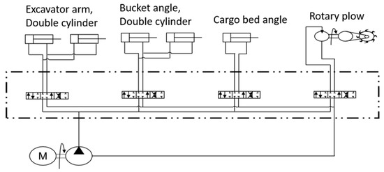
Figure 3.
Hydraulic pipeline design.
2.4. 3D Modeling of the Multifunctional Mini-Loader Vehicle
According to the vehicle function and size analysis results, the mechanical design of the vehicle mobile module and the hybrid power system is completed using CAD software, as shown in Figure 4. First, the modules that can move the vehicles, such as the driving wheel, the supporting wheel, the drag chain, the guide wheel, and the tracks are at the bottom. Second, the gearbox of the transmission system that is connected to the mobile module of the vehicle is next to the drive wheel. Then come the engine and the electric hydraulic pump. Finally, the hybrid power platform is at the top, including the engine, fuel tank, motor, generator, and a lithium battery that stores electricity. The designs of the hydraulic system and the tool modules required in the excavating module are shown in Figure 5.
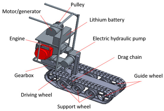
Figure 4.
3D diagram of the mini-loader.
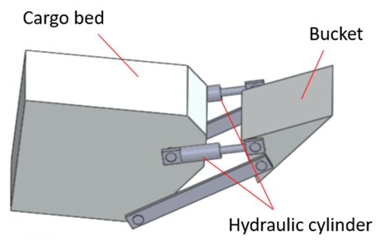
Figure 5.
3D diagram of the hydraulic system and the tool modules.
3. Results
3.1. Assembly of the Multifunctional Mini-Loader Vehicle
The complete assembly of the multifunctional mini-loader vehicle is shown in Figure 6. It contains the fuel engine, the motor module, the battery module, and the controller module are mounted on the platform to complete the mechanical assembly of the hybrid power system. Moreover, the assembly of the hydraulic system and the tool modules, which include the electric hydraulic pump module, the hydraulic valve module and the bucket hydraulic cylinder, and the cargo bed hydraulic cylinder.
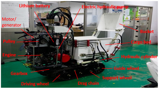
Figure 6.
Hybrid power multifunctional mini-loader vehicle.
3.2. Hybrid Power System and Hydraulic Pump System Tests
The tests of the hybrid power system include testing the engine, the hybrid power, and the battery mode. The steps involved in testing the engine mode is shown in Figure 7. The test first confirms that the engine fuel valve and the spark plug coil switch have been turned on. The controller is switched on, and the rotational direction of the motor is verified. The motor speed knob is turned; as the motor rotates, the engine ignites and starts successfully. If the engine does not start, a dipstick is used to check whether the fuel quantity is sufficient. After the engine starts, the motor is shut down, and the motor is converted to a generator to charge the battery. For battery charging, this study limits the maximum charging current to 5 amps and sets the charging mode to be turned on when the state-of-charge (SOC) is less than 60%. The measured charging current is shown in Figure 8. When the motor rotates, it consumes about 10 to 12 amps of current. When the motor is turned off, it becomes a generator, and the charging current is stable at 5 amps. At 30 s, the charging current suddenly drops. The reason is that the clutch is being connected and the low gear is engaged to move forward, which slows down the rotational speed slightly. By engaging the throttle, the current can be maintained at 5 amps.
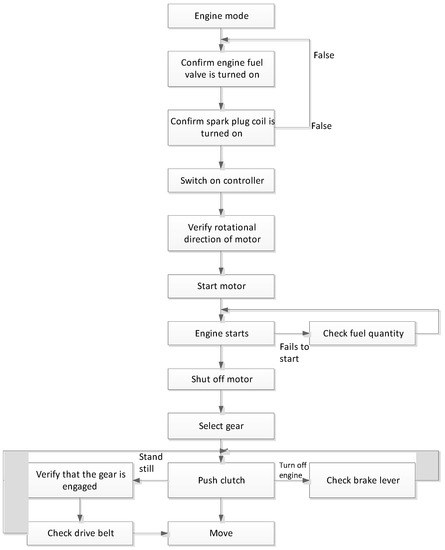
Figure 7.
Testing the engine mode.
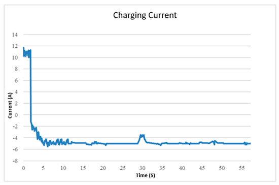
Figure 8.
Charging the battery module by the motor.
The hybrid power mode mainly controls the motor and the engine at the same rotational speed to increase torque. The testing procedure for the hybrid power mode is almost the same as that for the engine mode. The only difference is that the system controls the motor and the engine at the same rotational speed after the engine starts; if there is a speed difference, the power output becomes worse. The testing procedure for the motor power mode is the same as that for the engine and the hybrid power mode. It should be noted that when the residual capacity of the battery is lower than 60% during the motor mode, the system automatically switches to the engine mode to assist in battery charging. When the residual capacity is higher than 90%, the system switches back to the motor mode. The residual capacity of the battery and the usable time are calculated as in Equation (5):
In Equation (5), SOC is 60%, the charge is 12 Ah after charging is completed, and the average motor current is 10 A. The experimental record is shown in Figure 9. Therefore, it can be calculated that the battery has been used for 4.8 Ah and 28.8 min. This demonstrates that when the battery is used from 100% to 60%, the motor can run continuously for approximately 30 min. For the battery charging test, it takes about 40 min to charge to a residual capacity of 90% after switching to the engine mode.
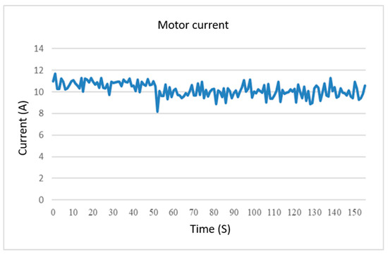
Figure 9.
Current measured by the motor during discharge.
The electric hydraulic pump operates smoothly after repeated experiments. The average time from the loading of the cargo to the clearing of the cargo into the cargo bed is 10 s.
3.3. Field Test
To understand the actual operation of the multifunctional mini-loader vehicle, the following field verifications are carried out according to the design specifications. The test results in Figure 10a demonstrates that the vehicle has the ability to operate in and out of a room with a door width of 770 mm. Figure 10b,c illustrates the ability of the vehicle to climb slopes, including 10% and 30% slopes. Figure 10d establishes that the vehicle has the ability to cross obstacles when encountering a threshold or a short step. This is tested by making the vehicle cross a short step of 140 mm in height. Figure 10e verifies that the vehicle can continue to operate when encountering puddles or potholes. This is tested by driving the loader through a trench of a certain width. After testing, the loader can successfully cross a 300 mm trench.
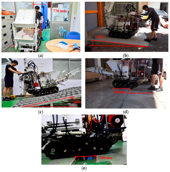
Figure 10.
Field test. (a) Vehicle testing of passing through a door; (b) vehicle testing of climbing 10% slope; (c) vehicle testing of climbing 30% slope; (d) vehicle testing of crossing a short step; (e) vehicle testing of crossing a trench.
4. Discussion
The results of the planned experiments demonstrate that the vehicle meets the design requirements which are longer operating time, better energy efficiency and less air pollution; however, there are some areas that require continuous improvement, including the hydraulic pump performance, climbing ability, obstacle crossing ability, and trench crossing ability and tools. which are discussed as follows.
- Longer operating time and better energy efficiency: The engine can operate at optimum conditions for a longer time, and can rest in the non-optimal operating range. Therefore, through the design of this study, the operation time and energy efficiency can be improved by using EM to provide power or starting battery charging mode to convert wasted power into electricity.
- Less air pollution: Air pollution can be reduced because the power system can adjust output torque in different operation conditions in a hybrid power mode. Avoiding inefficient engine operation can reduce carbon emissions caused by fuel combustion. With the help of hybrid powertrain design and the auxiliary output of generators and electric motors, the engine can run in the optimum efficiency range for a longer time, thus reducing air pollution and improving energy efficiency.
- Hydraulic pump performance: The electric hydraulic pump module successfully dumped the cargo into the cargo bed. During the dumping process, it is observed that when too close to the cargo, the operator is likely to inhale dust or be injured by small dumping. Therefore, the MB-3 hydraulic valve and the solenoid valve are modified to an electronic control mode, and a remote controller of the hydraulic valve is added for operators to use from 1 m away from the loading platform, improving the comfort and safety of personnel.
- Climbing ability: In the three power mode tests, the vehicle climbed 10% and 30% slopes. However, because the centers of gravity of the hybrid power system and the hydraulic system are closer to the user, when the slope angle is too large, the system may tilt upwards or slip downwards, and personnel may be injured. This problem can be overcome by two ideas. The first idea is changing the position of the center of gravity by moving forward the motor/generator and the battery module to the space above the electric hydraulic pump. The second idea is adding a parking brake to supply a moderate reverse force.
- Obstacle crossing ability: The test results demonstrate that the vehicle can cross a short step of 140 mm in height. However, because of the center of gravity of the hybrid power system being closer to the user, when the empty vehicle tracks halfway on the step, the track on the step is slightly dangling. Nevertheless, this does not cause a safety issue. The dangling phenomenon in the unloaded vehicle can be overcome that similar to discussion point 2. This idea not only reduces the overall height of the hybrid power module on the vehicle, but also improves the torque gap between clockwise and counterclockwise.
- Trench crossing ability: The loader crossed a 300 mm trench, but because the center of gravity is closer to the user, it should be noted that an unloaded vehicle may tilt upwards. The solution is the same as the second and third discussion points, which can be overcome by adjusting the center of gravity of the vehicle. This is conducive to overcoming the doubts of tilt upwards and slight dangling caused by climbing, and obstacle and trench crossing when the vehicle has no load.
- The current designed tools are suitable for excavation, soil transport, and soil loosening functions. In addition to meeting the requirements for agricultural farming, important functions required for disaster relief, such as grabbing and dozing tools, will also be considered in subsequent designs.
5. Conclusions
This study achieves the best energy efficiency by matching the power of the engine and the EM. Air pollution is reduced, the working environment is more operator-friendly, and the system can operate in narrow spaces. After the design is completed, the production, processing, assembly, and experiments are performed, and the results obtained during the research and testing process are summarized as follows.
- This study designed a hybrid power system according to the functional requirements. This hybrid power multifunctional mini-loader has the advantages of small size, improved energy efficiency, and reduced air pollution and is more operator-friendly.
- This study conducted experiments on the engine mode, the hybrid power mode, and the motor mode. The results demonstrate that the power system can increase the operating time by more than 30 min by interactive switching of the three modes.
- This study illustrates from field tests that the loader platform can pass through 770 mm wide gates, cross 140 mm high short steps, cross 300 mm trenches, and climb 30% slopes.
- The task of designing the excavation and transportation tools has been accomplished in this study. The structure of the module allows quick disassembly, and it can be extended to plowing and pesticide spraying functions and crucial functions required for disaster relief, such as grabbing tools and dozing tools.
Author Contributions
Conceptualization, P.-F.D.; methodology, P.-F.D.; software, P.-F.D.; validation, P.-T.C., P.-F.D. and K.D.H.; formal analysis, P.-F.D.; investigation, P.-F.D.; resources, C.-J.Y.; data curation, P.-F.D.; writing—original draft preparation, P.-T.C. and C.-J.Y.; writing—review and editing, P.-T.C. and C.-J.Y.; visualization, P.-F.D.; supervision, C.-J.Y. and K.D.H.
Acknowledgments
Authors thank Editage Academic Editing for English editing.
Conflicts of Interest
The authors declare no conflict of interest.
References
- Truong, D.Q.; Marco, J.; Greenwood, D.; Harper, L.; Corrochano, D.G.; Yoon, J.I. Challenges of micro/mild hybridisation for construction machinery and applicability in UK. Renew. Sustain. Energy Rev. 2018, 91, 301–320. [Google Scholar] [CrossRef]
- Chen, P.T.; Pai, P.H.; Yang, C.J.; Huang, K.D. Development of transmission systems for parallel hybrid electric vehicles. Appl. Sci. 2019, 9, 1538. [Google Scholar] [CrossRef]
- Chen, P.T.; Shen, D.J.; Yang, C.J.; Huang, K.D. Development of a hybrid electric motorcycle that accords energy efficiency and controllability via inverse differential gear and power mode switching control. Appl. Sci. 2019, 9, 1787. [Google Scholar] [CrossRef]
- Quan, Z.; Quan, L.; Zhang, J. Review of energy efficient direct pump controlled cylinder electro-hydraulic technology. Renew. Sustain. Energy Rev. 2014, 35, 336–346. [Google Scholar] [CrossRef]
- Wang, T.; Wang, Q. Efficiency analysis and evaluation of energy-saving pressure-compensated circuit for hybrid hydraulic excavator. Autom. Constr. 2014, 47, 62–68. [Google Scholar] [CrossRef]
- Bedotti, A.; Campanini, F.; Pastori, M.; Ricco, L.; Casoli, P. Energy saving solutions for a hydraulic excavator. Energy Procedia 2017, 126, 1099–1106. [Google Scholar] [CrossRef]
- Xia, L.; Quan, L.; Ge, L.; Hao, Y. Energy efficiency analysis of integrated drive and energy recuperation system for hydraulic excavator boom. Energy Convers. Manag. 2018, 156, 680–687. [Google Scholar] [CrossRef]
- Gong, J.; Zhang, D.; Guo, Y.; Liu, C.; Zhao, Y.; Hu, P.; Quan, W. Power control strategy and performance evaluation of a novel electrohydraulic energy-saving system. Appl. Energy 2019, 233–234, 724–734. [Google Scholar] [CrossRef]
- Shen, W.; Jiang, J.; Su, X.; Karimi, H.R. Control strategy analysis of the hydraulic hybrid excavator. J. Frankl. Inst. 2015, 352, 541–561. [Google Scholar] [CrossRef]
- Chen, Q.; Lin, T.; Ren, H. Parameters optimization and control strategy of power train systems in hybrid hydraulic excavators. Mechatronics 2018, 56, 16–25. [Google Scholar] [CrossRef]
- Lin, T.; Wang, Q.; Hu, B.; Gong, W. Research on the energy regeneration systems for hybrid hydraulic excavators. Autom. Constr. 2010, 19, 1016–1026. [Google Scholar] [CrossRef]
- Wang, T.; Wang, Q.; Lin, T. Improvement of boom control performance for hybrid hydraulic excavator with potential energy recovery. Autom. Constr. 2013, 30, 161–169. [Google Scholar] [CrossRef]
- Hao, Y.; Quan, L.; Cheng, H.; Xia, L.; Ge, L.; Zhao, B. Potential energy directly conversion and utilization methods used for heavy duty lifting machinery. Energy 2018, 155, 242–251. [Google Scholar] [CrossRef]
- Ge, L.; Quan, L.; Li, Y.; Zhang, X.; Yang, J. A novel hydraulic excavator boom driving system with high efficiency and potential energy regeneration capability. Energy Convers. Manag. 2018, 166, 308–317. [Google Scholar] [CrossRef]
- Chen, Q.; Lin, T.; Ren, H.; Fu, S. Novel potential energy regeneration systems for hybrid hydraulic excavators. Math. Comput. Simul. 2019, 163, 130–145. [Google Scholar] [CrossRef]
- Lin, T.; Chen, Q.; Ren, H.; Huang, W.; Chen, Q.; Fu, S. Review of boom potential energy regeneration technology for hydraulic construction machinery. Renew. Sustain. Energy Rev. 2017, 79, 358–371. [Google Scholar] [CrossRef]
- Wang, H.; Wang, Q.; Hu, B. A review of developments in energy storage systems for hybrid excavators. Autom. Constr. 2017, 80, 1–10. [Google Scholar] [CrossRef]
- He, X.; Jiang, Y. Review of hybrid electric systems for construction machinery. Autom. Constr. 2018, 92, 286–296. [Google Scholar] [CrossRef]
- Lin, T.; Wang, Q.; Hu, B.; Gong, W. Development of hybrid powered hydraulic construction machinery. Autom. Constr. 2010, 19, 11–19. [Google Scholar] [CrossRef]
- Baldizzone, S. Performance and Fuel Economy Analysis of a Mild Hybrid Vehicle Equipped with Belt Starter Generator. Ph.D. Thesis, University of Windsor, Windsor, ON, Canada, 2012. [Google Scholar]
- Steffan, R.; Hofmann, P.; Geringer, B. Potentials of a 48 Volt Belt-Starter-Generator in the Powertrain of an Ultra-Light Vehicle. In Proceedings of the SAE 2015 World Congress, New York, NY, USA, 2015, 14 April 2015. Paper ID 2015-01-1155, Detroit. [Google Scholar]
- Chen, P.T.; Yang, F.H.; Gao, H.M.; Huang, K.D. Moderate energy for charging Li-ion batteries determined by first-principles calculations. Batter. Supercaps 2018, 1, 209–214. [Google Scholar] [CrossRef]
- Chen, P.T.; Yang, F.H.; Cao, Z.T.; Jhang, J.M.; Gao, H.M.; Yang, M.H.; Huang, K.D. Reviving aged Lithium-ion batteries and prolonging their cycle life by sinusoidal waveform charging strategy. Batter. Supercaps 2019, 2, 673–677. [Google Scholar] [CrossRef]
- Chen, J.; Lin, M.; Lu, T. Parameter Matching Analysis and Application of Electric Vehicle Power System. In Proceedings of the 15th National Conference on Vehicle Engineering, Tainan, Taiwan, 26 November 2010. [Google Scholar]
- Mitsubishi Heavy Industries Engine. Available online: http://www.mhiet.co.jp/en/ (accessed on 5 May 2019).


© 2019 by the authors. Licensee MDPI, Basel, Switzerland. This article is an open access article distributed under the terms and conditions of the Creative Commons Attribution (CC BY) license (http://creativecommons.org/licenses/by/4.0/).