Hazard Analysis for Escalator Emergency Braking System via System Safety Analysis Method Based on STAMP


Abstract
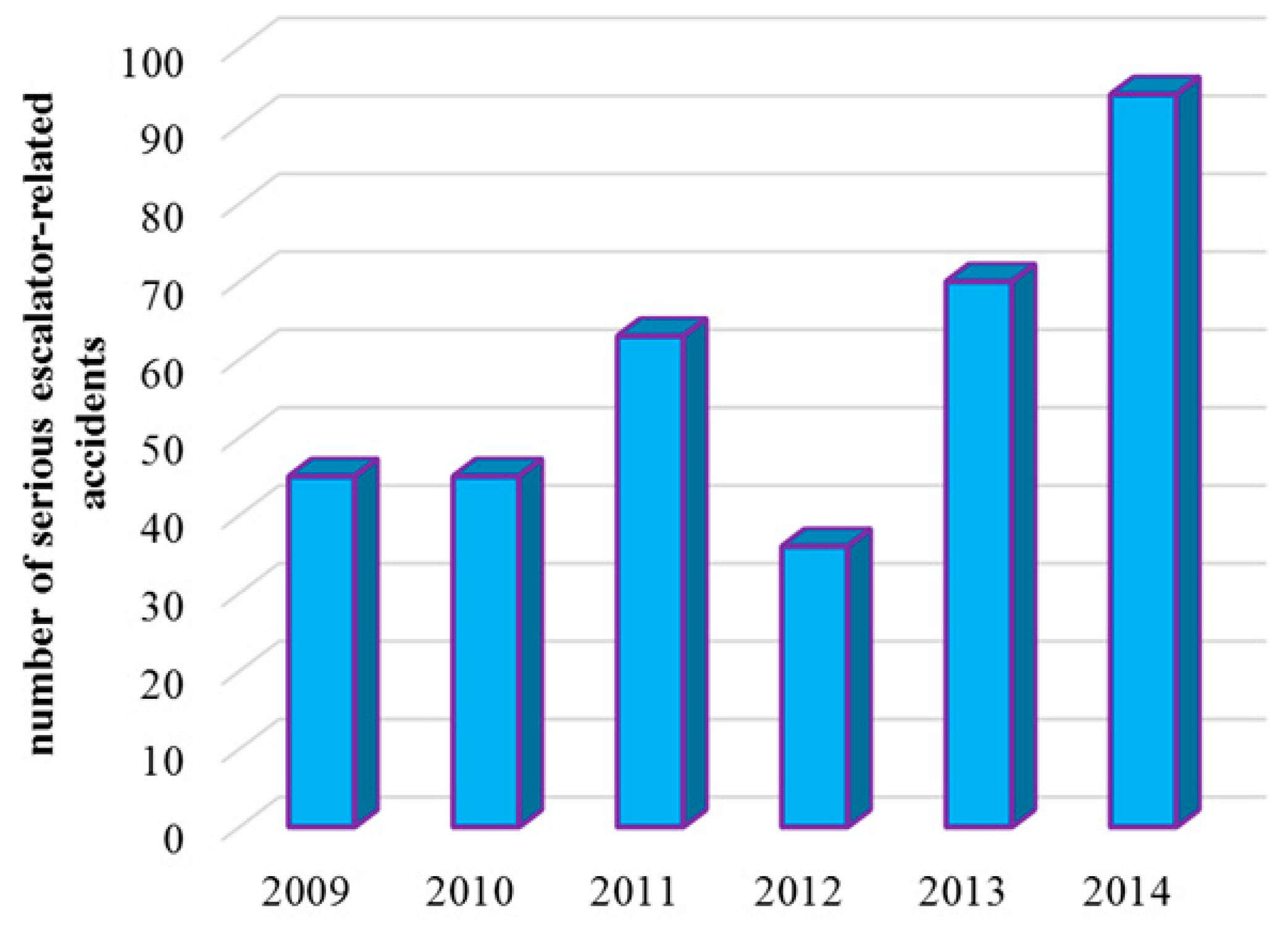
:1. Introduction
2. Safety Analysis Framework for Complex Electromechanical Equipment System Based on STAMP
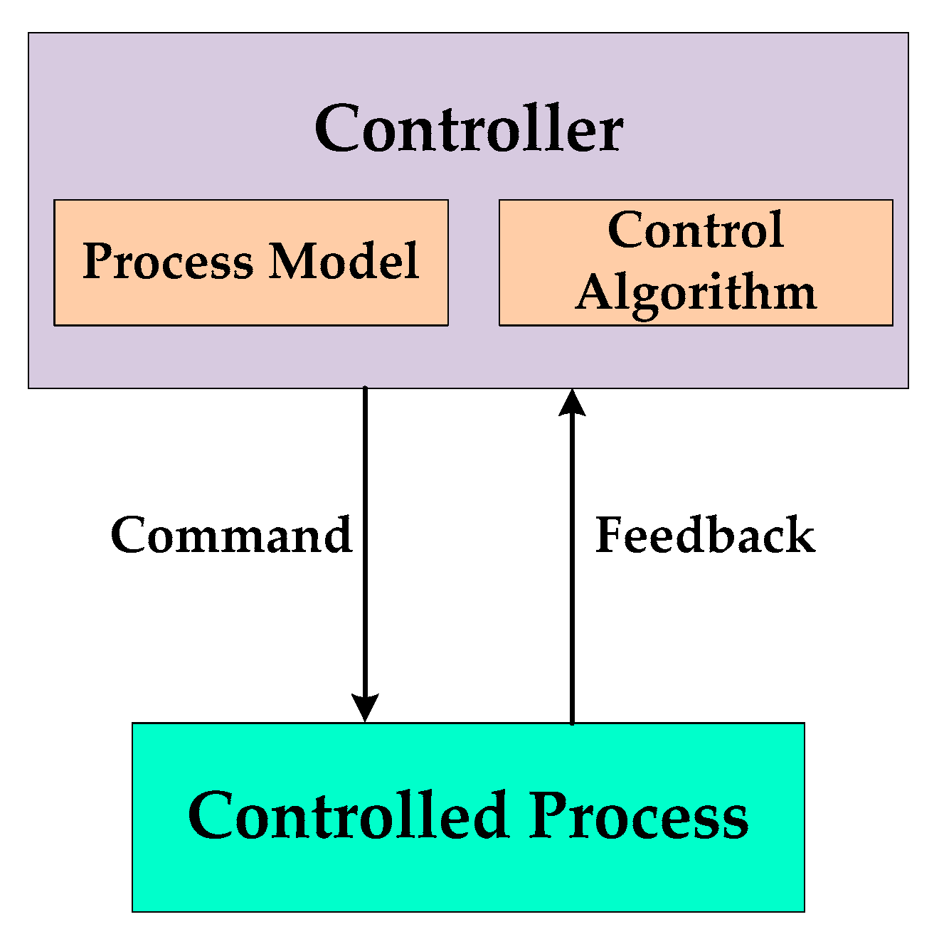
2.1. Principles of STAMP
2.2. Comparison between FTA, FMECA, HAZOP, and STAMP
2.3. System-Therotical Process Analysis (STPA)
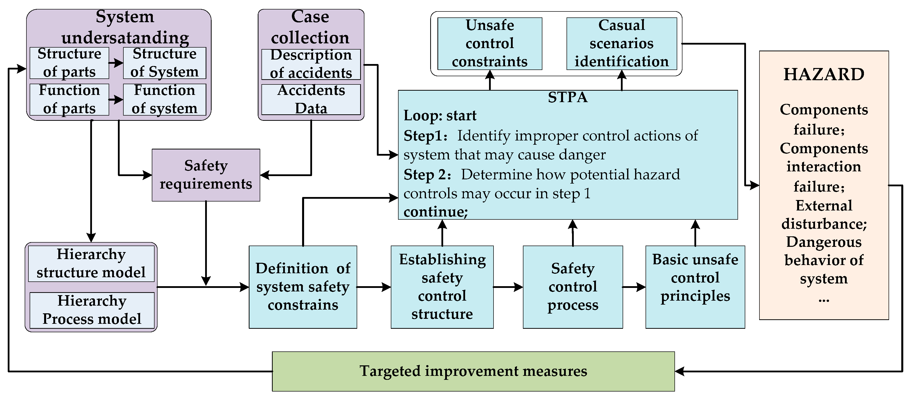
2.4. A Safety Analysis Framework for Complex Electromechanical System Based on STAMP
3. Hazard Analysis for Breaking System of Escalator
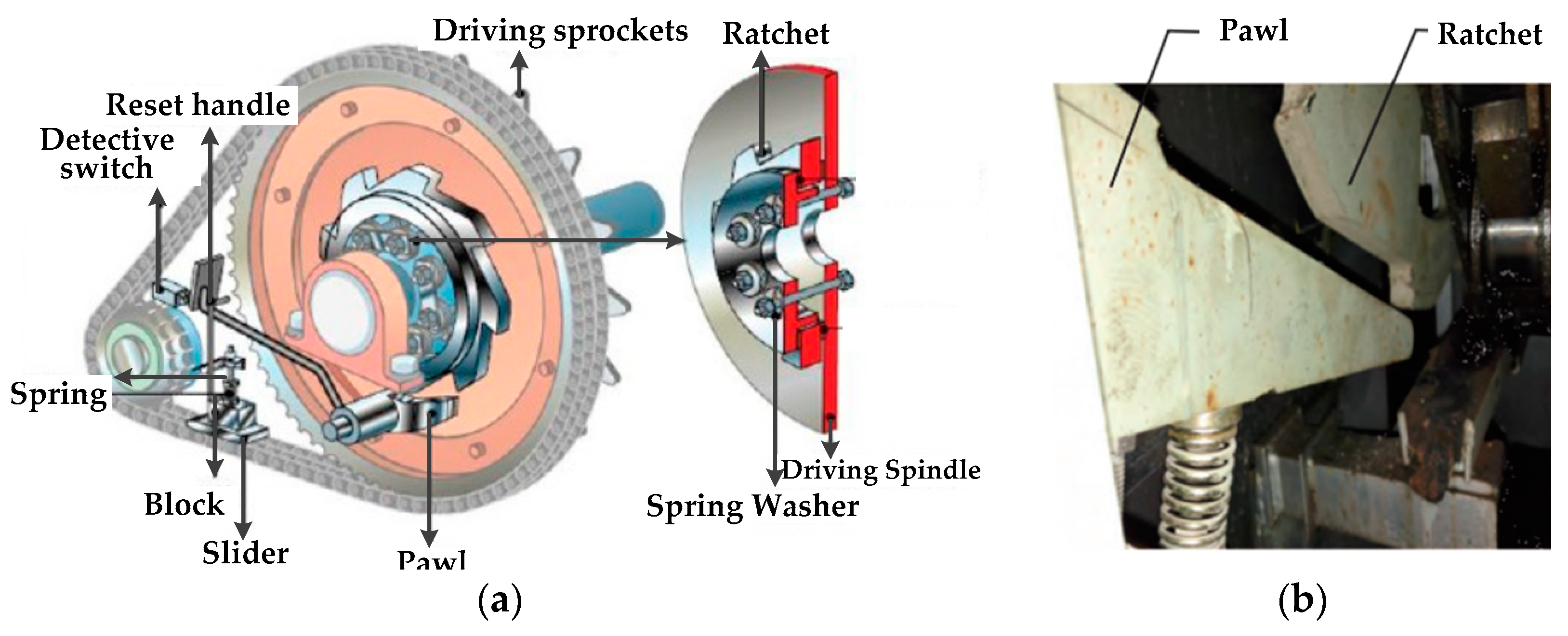
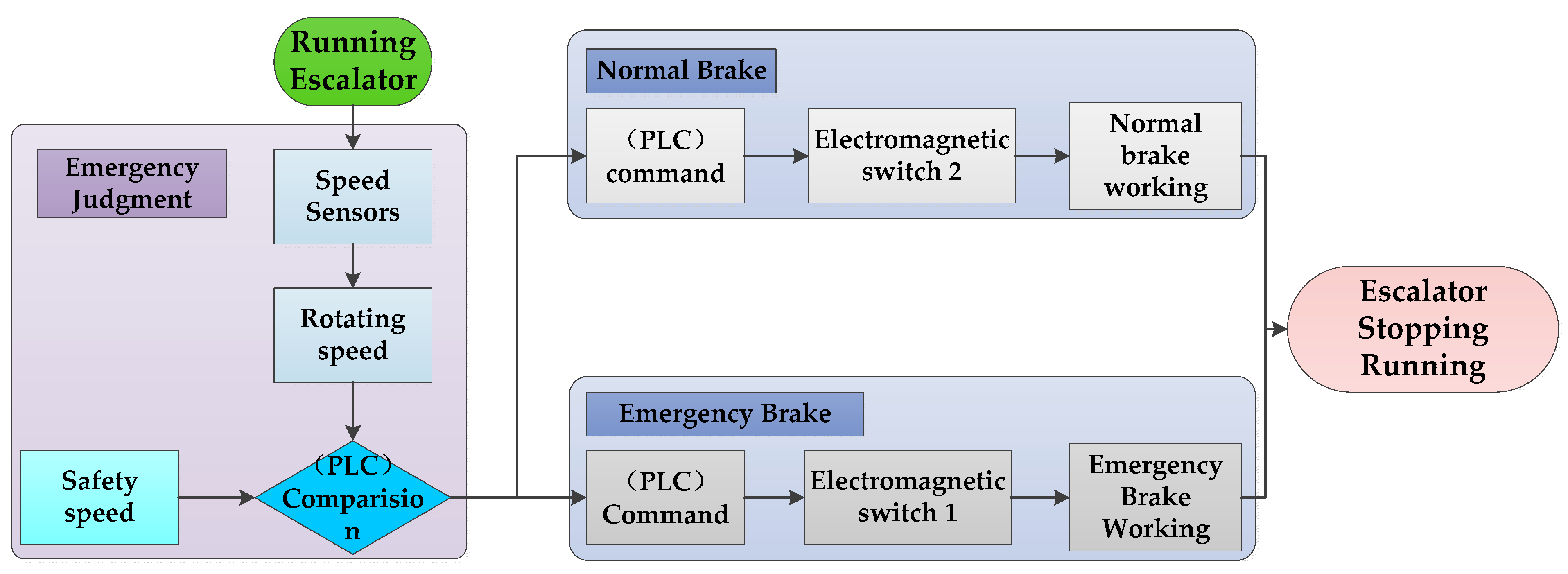
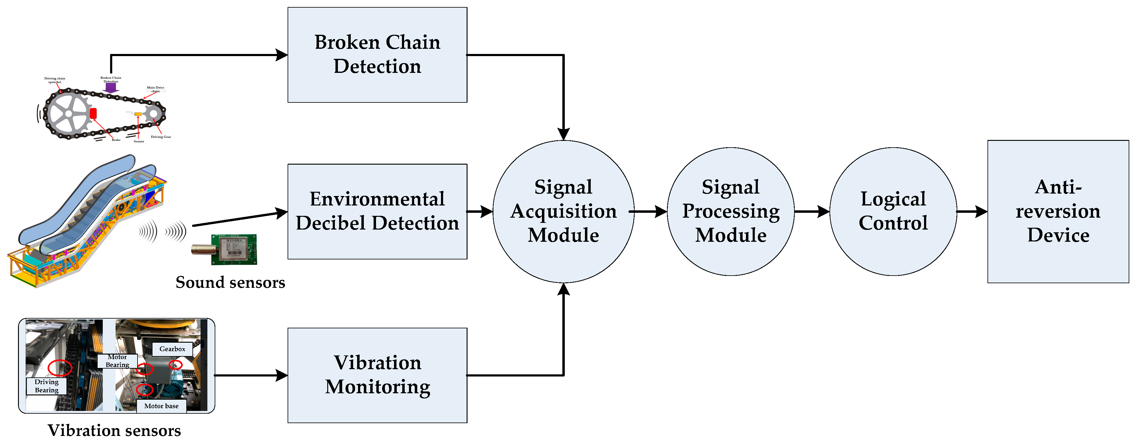
3.1. Overview of Escalator Emergency Breaking System
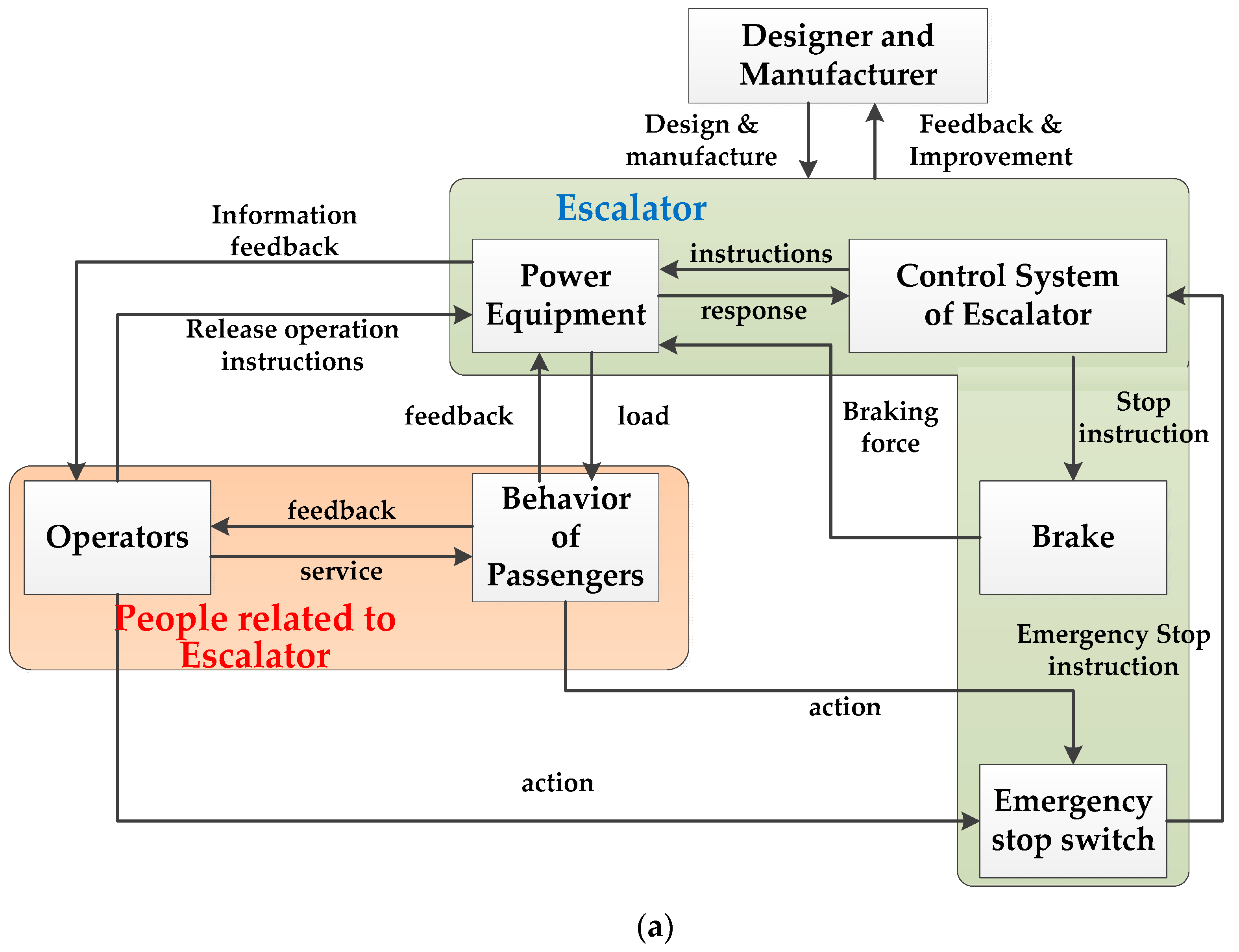
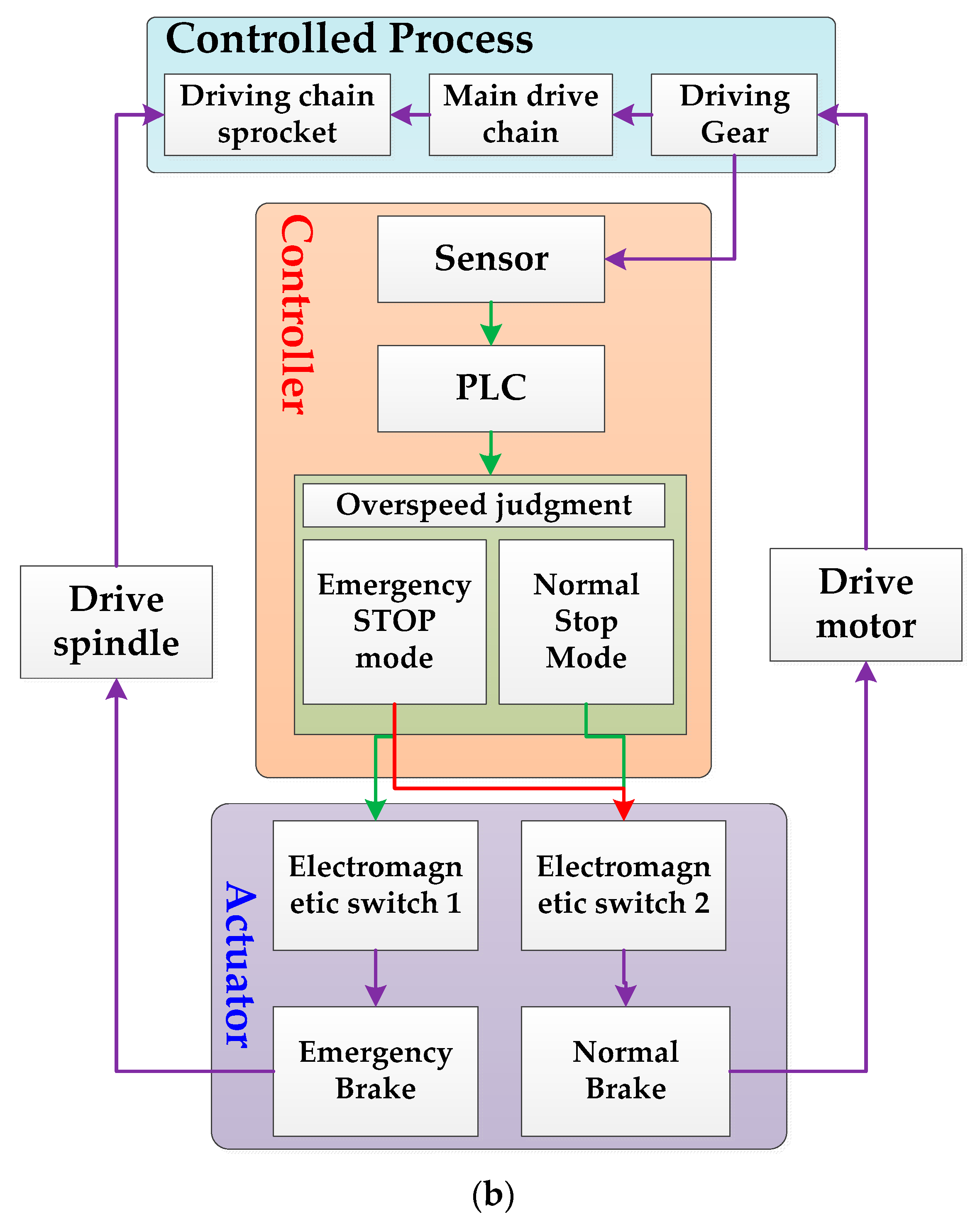
3.2. Control Structure of EEBS
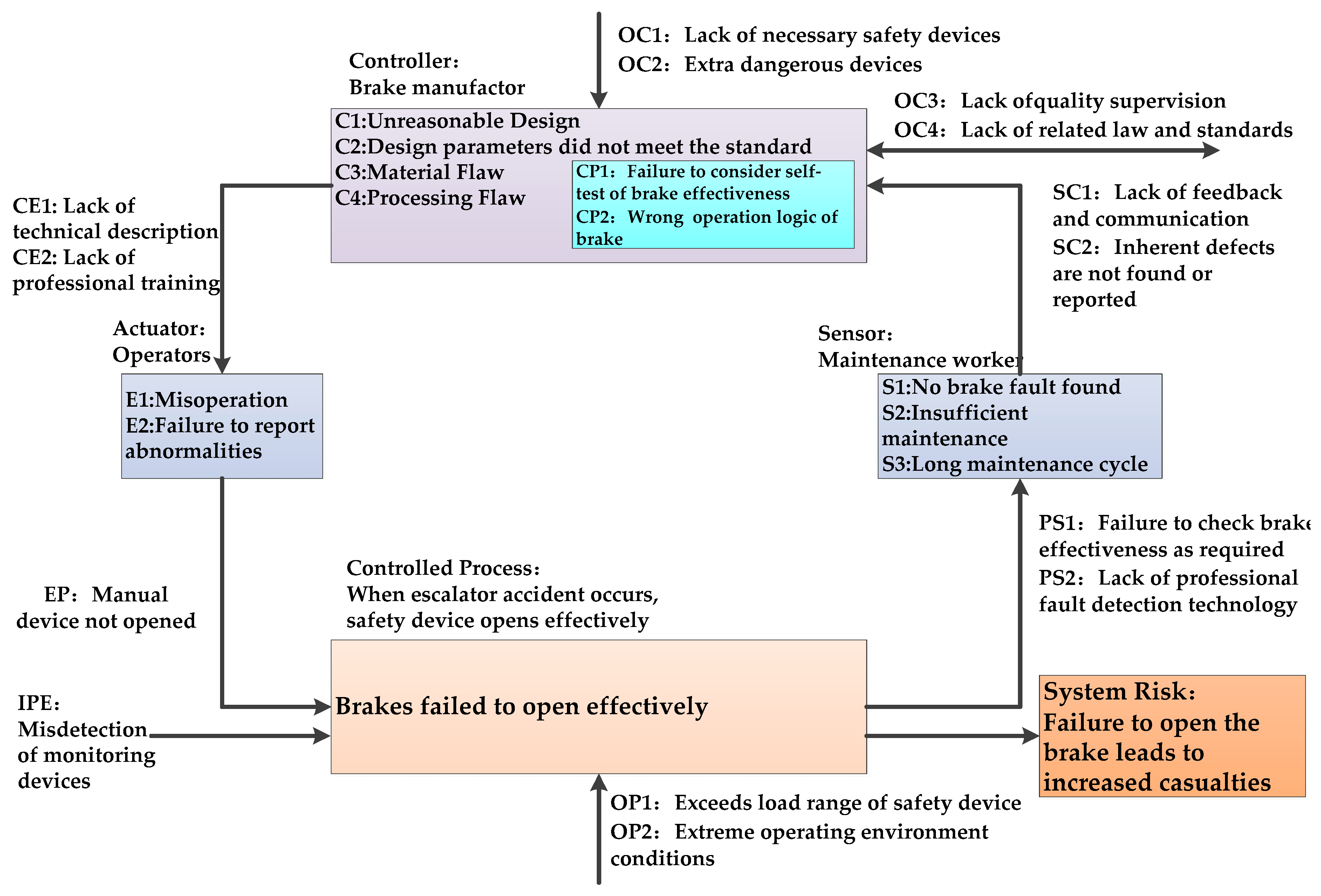
3.3. STPA for Escalator Breaking System
4. Result Analysis and Comparison with FTA
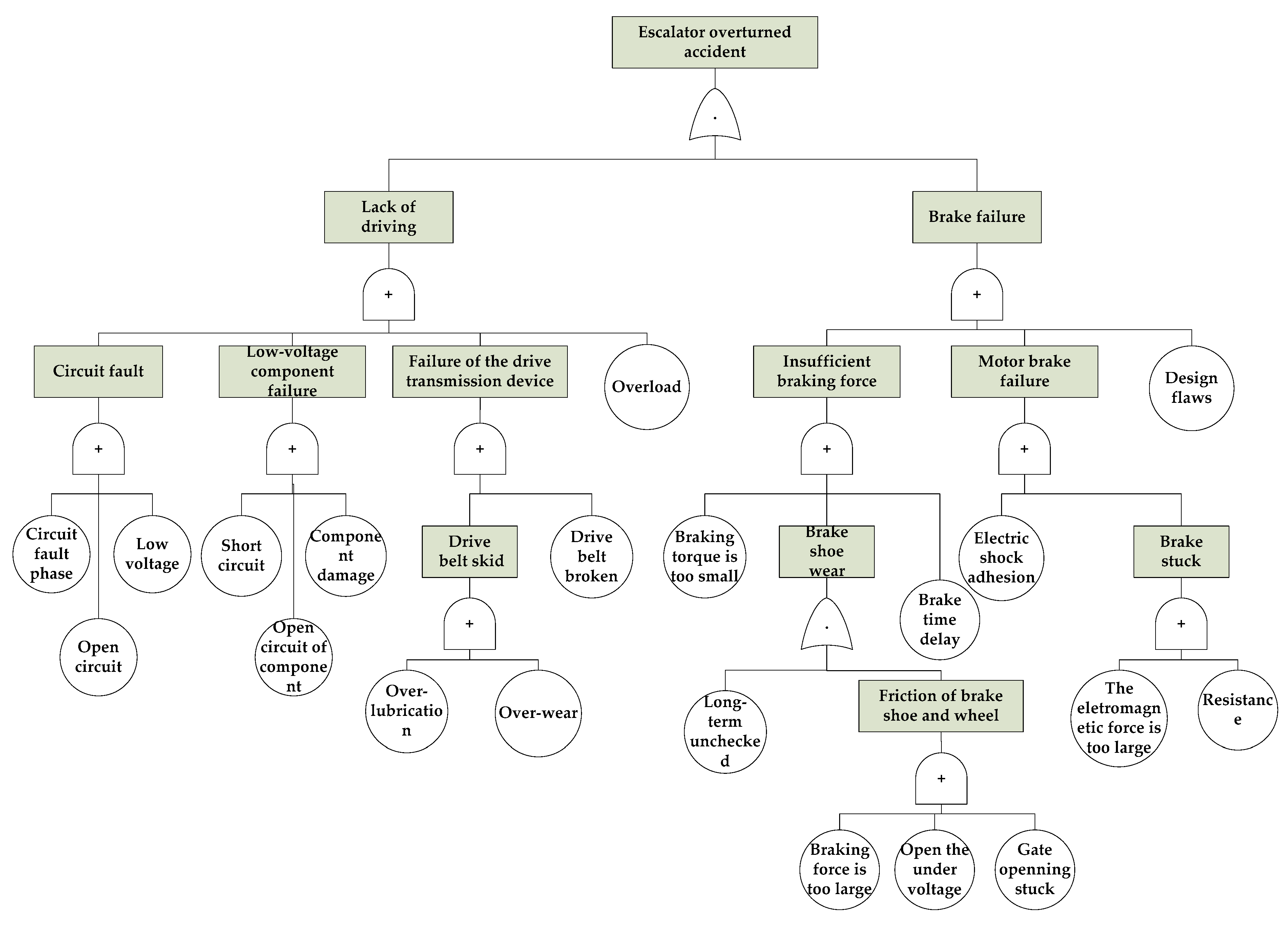
4.1. FTA of Escalator Breaking System
4.2. Result Comparison between FTA and STPA
4.3. Improvement on Control Process
5. Conclusions
Author Contributions
Funding
Acknowledgments
Conflicts of Interest
References
- Xing, Y.; Dissanayake, S.; Lu, J.; Long, S.; Lou, Y. An analysis of escalator-related injuries in metro stations in China, 2013–2015. Accid. Anal. Prev. 2017, 122, 332–341. [Google Scholar] [CrossRef] [PubMed]
- Shi, C.; Zhong, M.; Nong, X.; He, L.; Shi, J.; Feng, G. Modeling and safety strategy of passenger evacuation in a metro station in China. Saf. Sci. 2012, 50, 1319–1332. [Google Scholar] [CrossRef]
- Rogova, E.; Lodewijks, G. Braking system redundancy requirements for moving walks. Reliab. Eng. Syst. Saf. 2015, 133, 203–211. [Google Scholar] [CrossRef]
- Chan, J.P.; Gschwendtner, G. Braking performance analysis of an escalator system using multibody dynamics simulation technology. J. Mech. Sci. Technol. 2015, 29, 2645–2651. [Google Scholar]
- Mishra, K.M.; Huhtala, K. Elevator fault detection using profile extraction and deep autoencoder feature extraction for acceleration and magnetic signals. Appl. Sci. 2019, 9, 2990. [Google Scholar] [CrossRef]
- Greenwood, M.; Yule, G. An inquiry into the nature of frequency distributions representative of multiple happenings, with particular reference to the occurrence of multiple accidents or disease or repeated accidents. J. Roy. Stat. Soc. 1920, 83, 255. [Google Scholar] [CrossRef]
- Heinrich, H. Industrial Accident Prevention, 1st ed.; McGraw Hill: New York, NY, USA, 1932. [Google Scholar]
- Haddon, W. The changing approach to the epidemiology, prevention, and amelioration of trauma: The transition to approaches ethologically rather than descriptively based. Am. J. Public Health 1968, 58, 1431–1438. [Google Scholar] [CrossRef]
- Reactor Safety Study: An Assessment of Accident Risks in U.S. Commercial Nuclear Power Plants. Available online: URL https://digital.library.unt.edu/ark:/67531/metadc784367/ (accessed on 23 October 2019).
- Reason, J. Managing the Risks of Organizational Accidents; Ashgate: Adershot, UK, 1997. [Google Scholar]
- Perrow, C. Normal Accidents: Living with High-Risk Technologies; Basic Books: New York, NY, USA, 1984. [Google Scholar]
- Porte, T.R.L.; Consolini, P. Working in theory but not in practice: Theoretical challenges in high reliability organizations. J. Public Adm. Res. Theory 1991, 1, 19–47. [Google Scholar]
- Leveson, N.; Dulac, N.; Marais, K.; Carrol, J. Moving beyond normal accidents and high reliability organizations: A systems approach to safety in complex systems. Org. Stud. 2009, 30, 227–249. [Google Scholar] [CrossRef]
- Rasmussen, J. Risk management in a dynamic society: A modeling problem. Saf. Sci. 1997, 27, 183–213. [Google Scholar] [CrossRef]
- Leveson, N. A new accident model for engineering safer systems. Saf. Sci. 2004, 42, 237–270. [Google Scholar] [CrossRef]
- Mohaghegh, Z.; Mosleh, A. Incorporating organizational factors into probabilistic risk assessment of complex socio-technical systems: Principles and theoretical foundations. Saf. Sci. 2009, 47, 1139–1158. [Google Scholar] [CrossRef]
- Mohaghegh, Z.; Kazemi, R.; Mosleh, A. Incorporating organizational factors into probabilistic risk assessment (PRA) of complex socio-technical systems: A hybrid technique formalization. Reliab. Eng. Syst. Saf. 2009, 94, 1000–1018. [Google Scholar] [CrossRef]
- Fleming, C.H.; Leveson, N.G. Early concept development and safety analysis of future transportation systems. IEEE Trans. Intell. Transp. Syst. 2016, 1–12. [Google Scholar] [CrossRef]
- A Comparison of STPA and the ARP 4761 Safety Assessment Process Process. Available online: http://sunnyday.mit.edu/papers/ARP4761-Comparison-Report-final-1.pdf (accessed on 23 October 2019).
- Ishimatsu, T.; Leveson, N.G.; Thomas, J.P.; Katahira, M.; Miyamoto, Y.; Ujiie, R.; Nakao, H.; Hoshino, N.; Fleming, C.H. Hazard analysis of complex spacecraft using systems-theoretic process analysis. J. Spacecr. Rockets 2014, 51, 509–522. [Google Scholar] [CrossRef]
- Xiangkun, M.; Guoming, C.; Jihao, S.; Gaogeng, Z.; Yuan, Z. STAMP-based analysis of deepwater well control safety. J. Loss Prev. Process. Ind. 2018, 552018, 41–52. [Google Scholar]
- Mahajan, H.S.; Bradley, T.; Pasricha, S. Application of systems theoretic process analysis to a lane keeping assist system. Reliab. Eng. Syst. Saf. 2017, 167, 177–183. [Google Scholar] [CrossRef]
- Yunhua, G.; Yuntao, L. STAMP-based causal analysis of China-Donghuang oil transportation pipeline leakage and explosion accident. J. Loss Prev. Process. Ind. 2018, 56, 402–413. [Google Scholar]
- Chi, C.F.; Chang, T.C.; Tsou, C.L. In-depth investigation of escalator riding accidents in heavy capacity MRT stations. Accid. Anal. Prev. 2006, 38, 662–670. [Google Scholar] [CrossRef]
- Algin, A.; Gulacti, U.; Erdogan, M.O.; Tayfur, I.; Yusufoglu, K.; Lok, U. Escalator-related injuries in one of the deepest subway stations in Europe. Ann. Saudi. Med. 2019, 39, 112–117. [Google Scholar] [CrossRef]
- Kefan, X.; Zimei, L. Factors influencing escalator-related incidents in China: A systematic analysis using ISM-DEMATEL method. Int. J. Environ. Res. Public Health 2019, 16, 2478. [Google Scholar]
- Li, W.; Gong, J.; Yu, P.; Shen, S. Modeling, simulation and analysis of group trampling risks during escalator transfers. Phys. A. Stat. Mech. Appl. 2016, 444, 970–984. [Google Scholar] [CrossRef]
- Li, W.; Gong, J.; Yu, P.; Shen, S.; Li, Y.; Duan, Q. Simulation and analysis of congestion risk during escalator transfers using a modified social force model. Phys. A. Stat. Mech. Appl. 2015, 420, 28–40. [Google Scholar] [CrossRef]
- Lee, J.Y.S.; Lam, W.H.K.; Wong, S.C. Pedestrian Simulation Model for Hong Kong Underground Stations. In Proceedings of the Intelligent Transportation Systems, Oakland, CA, USA, 25–29 August 2001; pp. 554–558. [Google Scholar]
- Wang, W.; Li, X.; Pan, Q.L. Notice of Retraction Risk Management based on the Escalator Overturned Accident. In Proceedings of the International Conference on Quality, Reliability, Risk, Maintenance, and Safety Engineering, Emeishan, China, 15–18 July 2013; pp. 22–27. [Google Scholar]
- Priestley, K.; Lee, G. Human Factors in Railway Operations. Railway Engineering—Challenges for Railway Transportation in Information Age. In Proceedings of the ICRE 2008: International Conference on IET, Hong Kong, China, 25–28 March 2008. [Google Scholar]
- Anis, B.; Nga, N.; Faïda, M.; Jean-Yves, C.; Abdelfattah, M. Improved safety analysis integration in a systems engineering approach. Appl. Sci. 2019, 9, 1246. [Google Scholar]
- Yongming, Z.; Zhe, Y.; Feng, Y.; Jiawei, Y.; Bao, D. A novel reconstruction approach to elevator energy conservation based on a DC micro-grid in high-rise buildings. Energies 2019, 12, 33. [Google Scholar]
- Al-Kodmany, K. Tall buildings and elevators: A review of recent technological advances. Buildings 2015, 5, 1070–1104. [Google Scholar] [CrossRef]
- Stamatis, K. Predictive maintenance of hydraulic lifts through lubricating oil analysis. Machines 2014, 2, 1–12. [Google Scholar]
- Oh, S.; Hwang, D.; Kim, K.H.; Kim, K. Escalator: An autonomous scheduling scheme for convergecast in TSCH. Sensors 2018, 18, 1209. [Google Scholar] [CrossRef]


| Year | Passenger Flow Per Year (billion) | Total Injuries | Escalator-Related Injuries |
|---|---|---|---|
| 2013 | 1.99 | 418 | 291 |
| 2014 | 2.28 | 477 | 314 |
| 2015 | 2.40 | 520 | 345 |
| Method | Time&. by | Advantages | Disadvantages |
|---|---|---|---|
| FTA | 1961 By American Telephone & Telegraph Company | Concise expression of causality and logic; Predict and Prevent accident; Qualitative and quantitative analysis | Not for analysis of a process or equipment system; More steps and computational complexity for a complex system; The probability of all basic events needs to know for quantitative analysis etc. |
| FMECA | 1950s By United States Air Force | The whole process of product development; Principle and operation are simple; The base of other failure analysis | Heavy workload, time-consuming; Univariate analysis; Limited by environmental conditions; Poor generality of the conclusion, etc. |
| HAZOP | 1974 By Imperial Chemical Industries | Detailed analysis of process engineering; Design evaluation and operation evaluation; | Need professional groups to work; Ignore the interaction between subsystems |
| STAMP | 2004 By Massachusetts Institute of Technology | Understanding accidents from the perspective of system theory and cybernetics; Fully consider the interaction between systems; | Emphasize social factors; Mostly used for qualitative analysis and need to be combined with other methods for quantitative analysis |
| # | Control Process | From | to |
|---|---|---|---|
| 1 | C1 Design or manufacture | Designer or manufacturer | Brake system |
| 2 | C2 Running escalator | Operators | Control system |
| 3 | C3 Taking escalator | Passengers | escalator |
| 4 | C4 Control system running | Control system | Power system |
| 5 | C5 issue brake command | Control System | Brake |
| 6 | C6 Braking Process | Brake | Power system |
| 7 | C7 Emergency Stop | Operators or passengers | Control system |
| # | Control Action | From | to |
|---|---|---|---|
| 1 | C8. Speed Measurement | sensors | escalator |
| 2 | C9. State judgment by PLC | PLC control system | escalator |
| 3 | C10. Issue command by PLC | PLC control system | Brake system |
| 4 | C11. brake start | Electromagnetic switch | Pawl of brake |
| 5 | C12. Braking Process | Brake | Power system (Driving spindle) |
| # | Control Action | Not Provided | Incorrect Provided | Wrong Time or Wrong Sequence | Incorrect Duration |
|---|---|---|---|---|---|
| 1 | C1 Design or manufacture brake | UCA1 Lack verification | UCA2 original design flaw UCA4 unqualified processing | UCA3 development lifecycle (D & M) is too long | |
| 2 | C2 Escalator Running | UCA5 Lack effective means of supervision UCA6 No safety hints are set | UCA7 Keep running when escalator breakdown | UCA8 negligent management and maintenance for a long time | |
| 3 | C3 Taking escalator | UCA9 unsafe behavior or mental of passengers | UCA10 taking escalator when escalator break down | ||
| 4 | C4 Control system running | UCA11 out of control because of inherent fault | UCA12 wrong control command from staff | UCA13 Unreasonable design of control system | UCA14 control command delay |
| 5 | C5 issue brake command | UCA15 No brake command issued in emergency situation | UCA16 Brake command issued when escalator in normal operation | UCA17 Brake command delay when emergency | |
| 6 | C6 Braking Process | UCA18 Brake is not started | UCA19 Unsuccessful braking | UCA20 Brake when escalator in normal operation | UCA21 Escalator does not stop because of short brake time; UCA22 Serious wear because of long brake time |
| 7 | C7 Emergency Stop | UCA23 No operation in an emergency | UCA24 Wrong operation in an emergency | UCA25 operation in normal running |
| # | Control Action | Not Provided | Incorrect Provided | Wrong Time or Wrong Sequence | Incorrect Duration |
|---|---|---|---|---|---|
| 1 | C8 Speed Measurement using sensors | UCA26 Non installed sensor UCA27 Sensor damaged | UCA28 Measurement Error of sensor UCA29 improper installation position UCA30 signals from sensor are disturbed | UCA31 Resolution or sample rate is low | |
| 2 | C9 state judgment by PLC | UCA32 incorrect state judgment algorithm | UCA33 wrong state judgment | UCA34 state judgment required time is too long | |
| 3 | C10 Issue command by PLC | UCA35 No brake command issued by PLC | UCA36 Wrong brake command issued by PLC | ||
| 4 | C11 brake start | UCA37 The electromagnetic switch failed to start normally | UCA38 The contact fault of electronic components was not detected | UCA39 Electromagnetic switch starting in normal operation | UCA40 The action time of the electromagnetic switch is too long; UCA41 The response time of the brake is too long |
| 5 | C12 Braking Process | UCA42 Pawl is not working | UCA43 No effective deceleration of brake operation | UCA44 rake when escalator in normal operation | UCA45 short brake time; UCA46 Serious wear because of long brake time |
| Unsafe Control (Incentives) | Example Scenario |
|---|---|
| Unreasonable installation location; Signal from sensor is disturbed; sensor damaged | The sensor does not measure the change effectively when overspeed occurs, which resulting in the PLC not making correct overspeed judgments. |
| Component of PLC damaged | Velocity judgment can be wrong and command mistake because of the component of PLC damaged. |
| Unreasonable overspeed judgment algorithm; Trigger threshold of overspeed judgment is too high or too low | The misjudgment of overspeed can lead to frequent starts of emergency brake system, which would influence the operation of escalator and aggravating the wear of mechanical components. |
| Command mistake from PLC | The brake command is sent during normal operation or the command is not sent when the speed exceed the safe threshold, or there is a delay in the command, increasing the response time of brake system. |
| Component of brake damaged | The mechanical component of brake system can’t afford the instantly impact force and energy when it needs to work. |
| Component of Driving spindle damaged | The risk of losing power would be increased when components of driving spindle are damaged |
| High traffic flow | (1) the escalator is running under a heavy load, which would increase the wear of components and risk of component damage; (2) high traffic flow can easily lead to chain reaction and butterfly effect of unsafe behavior |
| Unsafe behavior and mental state of passenger | The passengers did not grasp the handrails. When an accident occurred, it caused panic, stampede, and increased brake load. |
| Response time of brake system is too long when accident occurs | When the accident occurs, the overspeed judgment time is long, the PLC does not issue the instruction in time, or the braking time is too short, or the passengers have a long reaction time, all of which cause the time course of the brake action process to be longer than the time course of the accident |
| Object | Identified by Both FTA and STPA | Identified by STPA Only |
|---|---|---|
| sensors | Sensors damaged | Unreasonable installation location; Signal from sensor is disturbed |
| PLC | Component of PLC damaged | overspeed threshold setting; Command delay; Error algorithm |
| Brake | Component of brake damaged; Braking force is small | Braking signal trigger setting; Unreasonable trigger threshold; short braking duration |
| Driving spindle | Component of driving spindle damaged | Long time load |
| Passengers | Heavy load (high traffic flow) | Reaction time of passengers; Mental states of passengers; Long traveling time |
© 2019 by the authors. Licensee MDPI, Basel, Switzerland. This article is an open access article distributed under the terms and conditions of the Creative Commons Attribution (CC BY) license (http://creativecommons.org/licenses/by/4.0/).
Share and Cite
Zhou, Z.; Zi, Y.; Chen, J.; An, T. Hazard Analysis for Escalator Emergency Braking System via System Safety Analysis Method Based on STAMP. Appl. Sci. 2019, 9, 4530. https://doi.org/10.3390/app9214530
Zhou Z, Zi Y, Chen J, An T. Hazard Analysis for Escalator Emergency Braking System via System Safety Analysis Method Based on STAMP. Applied Sciences. 2019; 9(21):4530. https://doi.org/10.3390/app9214530
Chicago/Turabian StyleZhou, Zitong, Yanyang Zi, Jinglong Chen, and Tong An. 2019. "Hazard Analysis for Escalator Emergency Braking System via System Safety Analysis Method Based on STAMP" Applied Sciences 9, no. 21: 4530. https://doi.org/10.3390/app9214530