Abstract
Although non-invasive brain stimulation techniques do not involve surgical procedures, the challenge remains in correctly locating the stimulator from outside the head. There is a limit to which one can manually and precisely position and orient the stimulator or repeatedly move the stimulator around the same position. Therefore, in this study, we developed a serial robot with 6 degrees-of-freedom to move the stimulator and a neuro-navigation system to determine the stimulus point from looking at the shape of the subject’s brain. The proposed robot applied a spherical mechanism while considering the safety of the subject, and the workspace of the robot was designed considering the shape of the human head. Position-based visual servoing was applied to compensate for unexpected movements during subject stimulation. We also developed a neuro-navigation system that allows us visually to check the focus of the stimulator and the human brain at the same time and command the robot to the desired point. To verify the system performance, we first performed repeatability and motion compensation experiments of the robot and then evaluated the repeated biosignal response experiments through transcranial magnetic stimulation, a representative technique of non-invasive brain stimulation.
1. Introduction
Scientists have been trying to understand how the brain functions through brain stimulation, which includes both invasive and non-invasive stimulation techniques. Although invasive methods have advantages of high resolution and controllability of stimulation depth, they require brain surgery, which involves complications and potentially fatal risks. Non-invasive methods, in contrast, do not endanger the patient, as surgery is not necessary. Transcranial magnetic stimulation (TMS) is one of the most representative non-invasive stimulation methods [1]. The therapeutic application of TMS is widely used in neurology or psychiatry for the treatment of depression or schizophrenia. Thus, the number of studies on treating neuropsychiatric disease using TMS has increased rapidly.
Unfortunately, there is a technical difficulty in implementing this non-invasive brain stimulation method. Since TMS is a neuromodulation technique using a coil that generates a magnetic field, it must be fixed in the direction and position above the subject’s head [2]. Generally, manual positioning with a fixing arm is being used in clinical setups, but this procedure is complicated and time-consuming. Furthermore, patients should keep their head pose fixed during the treatment, which causes discomfort, because some treatments can take considerable time. For example, it takes more than 30 min for every session in the treatment of neuropsychiatric diseases [3]. For this reason, there have been studies on the development of a wearable positioning device to automatically position the brain stimulator [4]. It was designed for ultrasonic transducers that are far smaller in volume and lighter than TMS coils. Thus, we cannot apply it to TMS stimulation. In this study, a 6 degrees-of-freedom (DOF) serial manipulator was designed to enable the automatic positioning of TMS coils. The robot manipulator has an advantage in terms of accuracy and repeatability compared with manual positioning.
Unlike typical 6-DOF serial manipulators, the developed manipulator has a spherical mechanism. By using a spherical joint in this manipulator, the shape of its workspace can also be made spherical. Therefore, not only is the moving of the manipulator highly dexterous and concise (as the workspace is only required to cover the human brain [5]), but also the manipulator can easily avoid gratuitous singular points. The spherical mechanism has been applied to the medical robot field because it can minimize robot movement and improve patient safety [6,7]. In addition, a research study on robotic brain stimulation employed it to compensate for the unexpected movement of the subject [8]. We employed position-based visual servoing (PBVS) to compensate for the unexpected movement of the subject [9,10,11].
Although the robot can be moved to the desired position of the brain, a neuro-navigation system is required to determine the stimulus point while showing the brain [12,13,14,15]. The system aligns the subject’s medical image coordinates (e.g., computed tomography (CT), magnetic resonance imagining (MRI), functional MRI) with human coordinates, facilitating non-invasive brain stimulation, because the experimenter can simultaneously see the focus of the stimulator and the cortex of the brain. By selecting the desired stimulus point on the screen, one can easily determine the stimulation target.
In this study, we developed an integrated system for non-invasive brain stimulation and conducted experiments to verify precise stimulation. First, a repeatability experiment was conducted to verify how consistently the developed system could locate the stimulator to a desired posture. A motion compensation experiment was executed to confirm the control to compensate for the small movements of the person that would occur during the brain stimulation experiment. Finally, an integrated system was used to confirm the accuracy of the repeated stimulus by measuring electromyography (EMG) signals from electrodes that were attached to the patients’ arm and detecting the motor-evoked potential (MEP) to confirm that the same cortical stimulation could be repeated.
The rest of this paper is structured as follows. Section 2 introduces the entire system integrating the positioning robot and navigation system. The kinematic analysis of the robot, finite-element method (FEM) and modal analysis, and control method of the robot are described in Section 3. The functions used in the developed navigation program and the coordinate system used in the whole system are explained in detail in Section 4. The evaluation of the robot’s repeatability [16,17], accuracy, and repeated stimulation experiments is analyzed in Section 5. Finally, Section 6 concludes with a planned experiment and an overview of the research using the developed integrated system.
2. Overall System
To improve the curative effectiveness of treatments using non-invasive brain stimulation, the target locations should be stimulated accurately and repetitively. Furthermore, the determined relative posture between the stimulator and the head should be maintained during the treatment which usually lasts about 40 min [3]. Unpredictable motions of patients should be compensated for in real time to maintain the stimulation accuracy during treatment. In addition, it is important to save disease- and patient-specific target locations because these areas vary across diseases and individuals. The automatic relocation function helps achieving consistent performance in every treatment and reduces the preparation time for treatments.
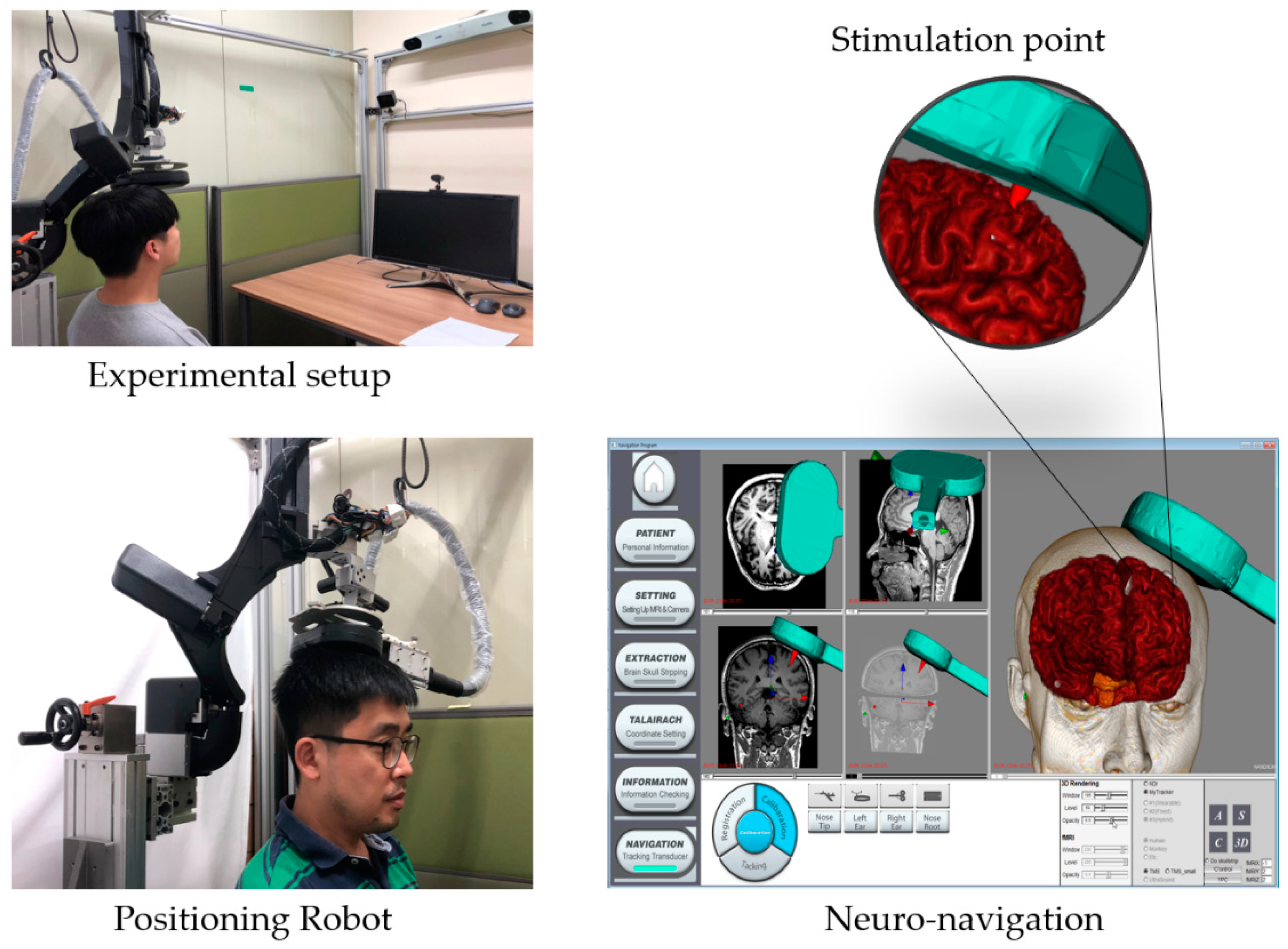
To satisfy these requirements, the proposed system was designed with a spherical robotic positioning device and a neuro-navigation system, as shown in Figure 1. Compared to the conventional manual positioning method, a robotic positioning device offers various advantages, such as precise positioning, good repeatability, and compensation of patient movements. The neuro-navigation system not only shows the current location of the stimulator with respect to the patient’s head but also works as a graphical user interface (GUI) for controlling the positioning robot. For examples, the target stimulation spot is set on this GUI.
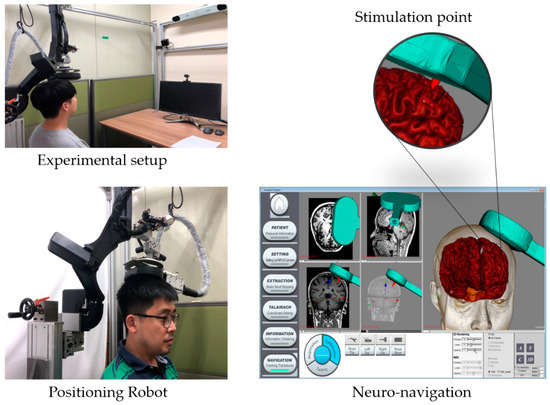
Figure 1.
Developed system for non-invasive brain stimulation.
3. Spherical Robotic Positioning Device
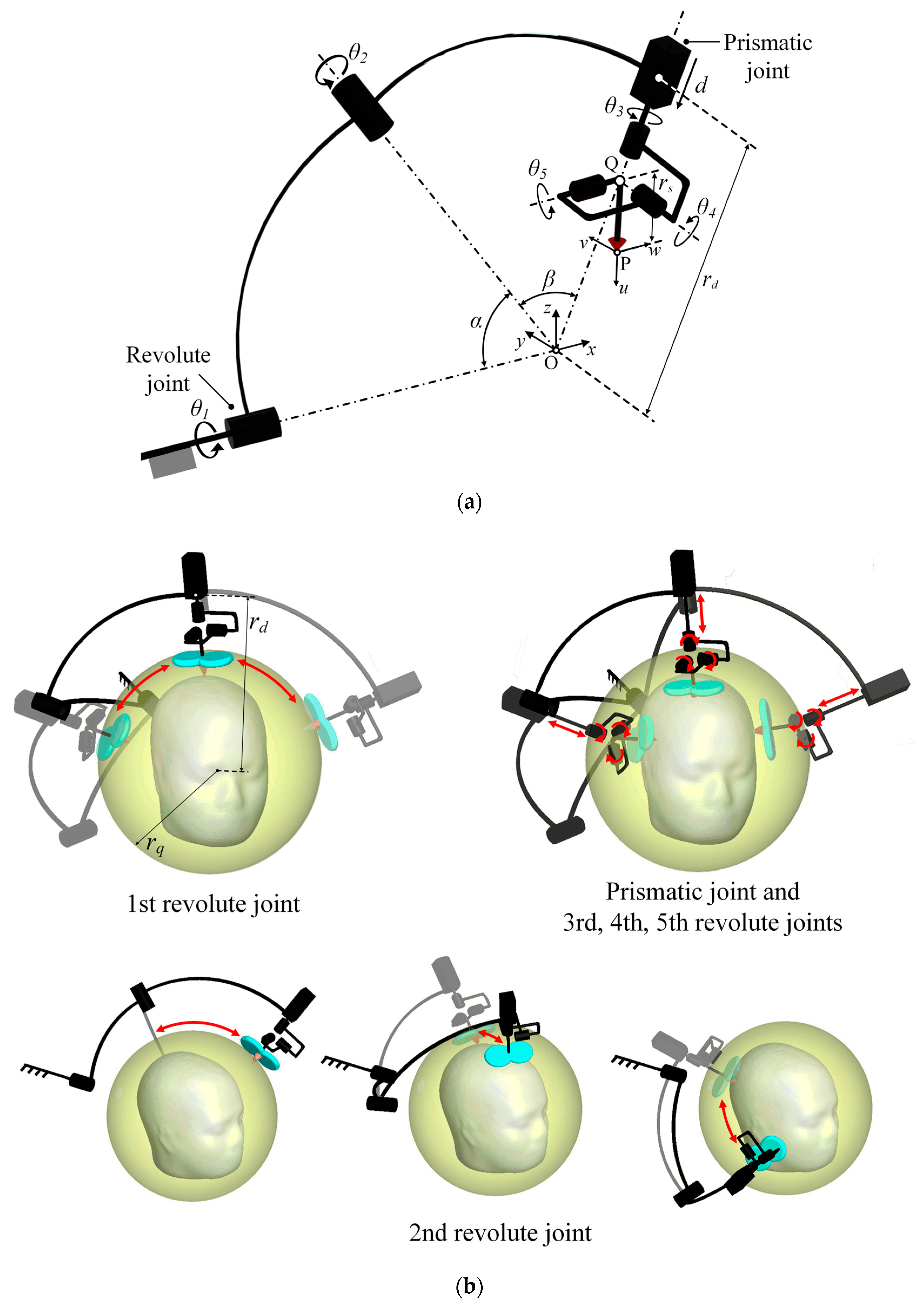
A schematic diagram of the proposed robotic positioning system is presented in Figure 2a. The configuration of the mechanism and arrangement of joints are, respectively, a serial manipulator with 6-DOF and an RRPRRR chain (R: revolute joint and P: prismatic joint). The rotational axes of the first, second, and third revolute joints are aligned to coincide with the origin O, and each joint is connected with spherical frames. Although the final stimulator posture is determined based on the combined motion of each joint, the configuration of each joint was designed according to a main role during device operation. The main roles of the first and second revolute joints, which take as the input values (, ), is generating large movements of the end-effector with the initial length () of the prismatic joint. It enables the robotic positioning device to move at the outer spherical space of radius , which is represented as a yellow spherical space in Figure 2b and it is hereinafter called a safety space. In other words, the stimulator can be transferred rapidly along a large path connecting two arbitrary points on the safety space using only two revolute joints. It is an efficient movement compared to the movement of serial manipulators using all actuators. Moreover, in this movement, the safety for patient is guaranteed because all parts of the device including a stimulator are moved at the outer of the safety space. The roles of the third, fourth, and fifth revolute joints (, , ) is controlling the stimulator orientation because their axes are designed to intersect at the point Q and are mutually orthogonal. The prismatic joint () adjusts the depth of stimulation. The movement of joints except the first and second actuators locates the stimulator at the target position exactly and slowly in the inner of the safety space, as shown in Figure 2b. For these reasons, this design configuration improves the efficiency of device movement around the head and safety for patients. With this proposed configuration, the device can move in highly dexterous manner, and can avoid singularity generated by kinematic characteristics. The desired payload was set to be 2 kg considering the commercial TMS stimulator (TAMAS, REMED Co., Republic of Korea). is set to be 260 mm considering the average size of the human head and the stimulator thickness [5].
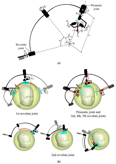
Figure 2.
(a) Schematic diagram of the developed positioning device and (b) motions of device according to movements of each joint.
3.1. Inverse Kinematic Analysis
A base coordinate and a moving coordinate, and , are assigned to the ground and the stimulator, respectively, as shown in Figure 2. In this study, for analyzing inverse kinematics, two vector loops are employed. The first vector loop, which passes through the points O, P, and Q, is the transformation () including information related to the desired posture. The second vector loop is the transformation () through the actuators from the origin (O) to the point Q. When the position vector of the stimulator () and its rotation matrix are given, the transformation matrix is obtained as follows:
where is the transformation matrix of translation from the origin to point P, and (axis, value) is the transformation matrix of translation along a particular axis. Then, the transformation matrix (), which is composed of the input values () of the revolute joints and the input value () of the prismatic actuator, can be expressed as
where (axis, value) is the transformation matrix of rotation along a particular axis. In Equations (1) and (2), and are the distances between point O and the initial position of the prismatic joint and between point Q and the stimulation focus (P), respectively. and are the design angles of the spherical frames. Because each component of and should be equal, the desired values () of each joint are derived as follows:
where c is cos and s is sin, ,
Using the derived input values, the end-effector of the device can be located with the target position and orientation. Moreover, to avoid singularity, the second joint should be driven in range < < 180. The range of the first revolute joint is also set as −180 < < 180.
3.2. 3D-Modeling
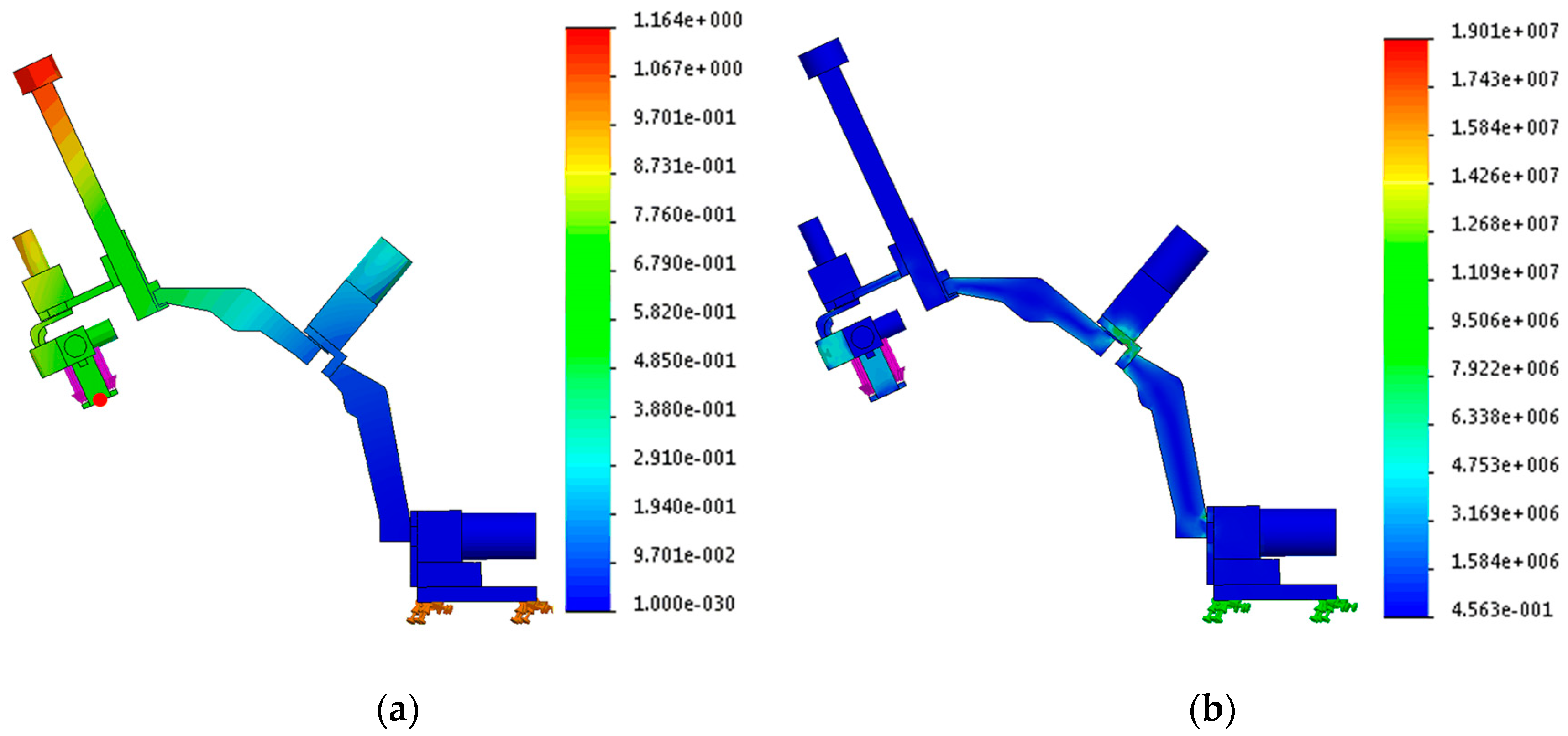
Although the use of a spherical configuration for the first two frames is a good design choice for improving the physical safety and movement efficiency of the end-effector, deflection can be produced easily as in the case of hinges when two spherical frames are stretched. In addition, when an external force is applied to the device, that is, when the device is decelerated and is stopped, vibration problems can occur in a spherical configuration. These mechanical characteristics reduce the accuracy of the device. Therefore, for reducing error produced by hardware and for achieving sufficient strength and stiffness, the thicknesses and shapes of the spherical frames are decided based on two interpretations: The analysis related to the deflection and stress distribution and modal analysis using the finite element method (FEM). Two interpretations are performed in a configuration that the two spherical frames are stretched completely, as shown in Figure 3, because the closer the configuration of the serial mechanism to a beam is, the larger the deflection that is produced. For performing FEM, all parts are considered as a rigid body.
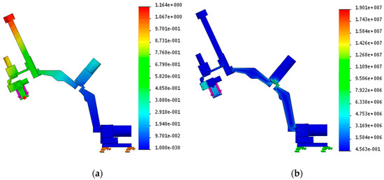
Figure 3.
(a) Result of deflection. The deflection at the red point is 0.664 mm and (b) Result of stress distribution. The maximum stress distribution is .
The simulations of deflection and stress distribution are performed in conditions that the base frame is fixed on the ground, material of the rigid body is set as aluminum 6061, and an external force with 30 N is applied at the center of the end-effector, which is sufficient force magnitude because the desired payload is 2 kg. The conditions except the external force are applied to the simulation of modal analysis. The result is presented in Figure 3a. The deflection at the red point of the end-effector is 0.664 mm, and the maximum stress distribution is . Because the tensile strength of aluminum 6061 is 55.2 MPa, the developed device has adequate strength in the given conditions. The configuration has the natural frequency of 18 Hz, which was thought to be enough because the system will be controlled to move slowly at most a few tens of centimeters.
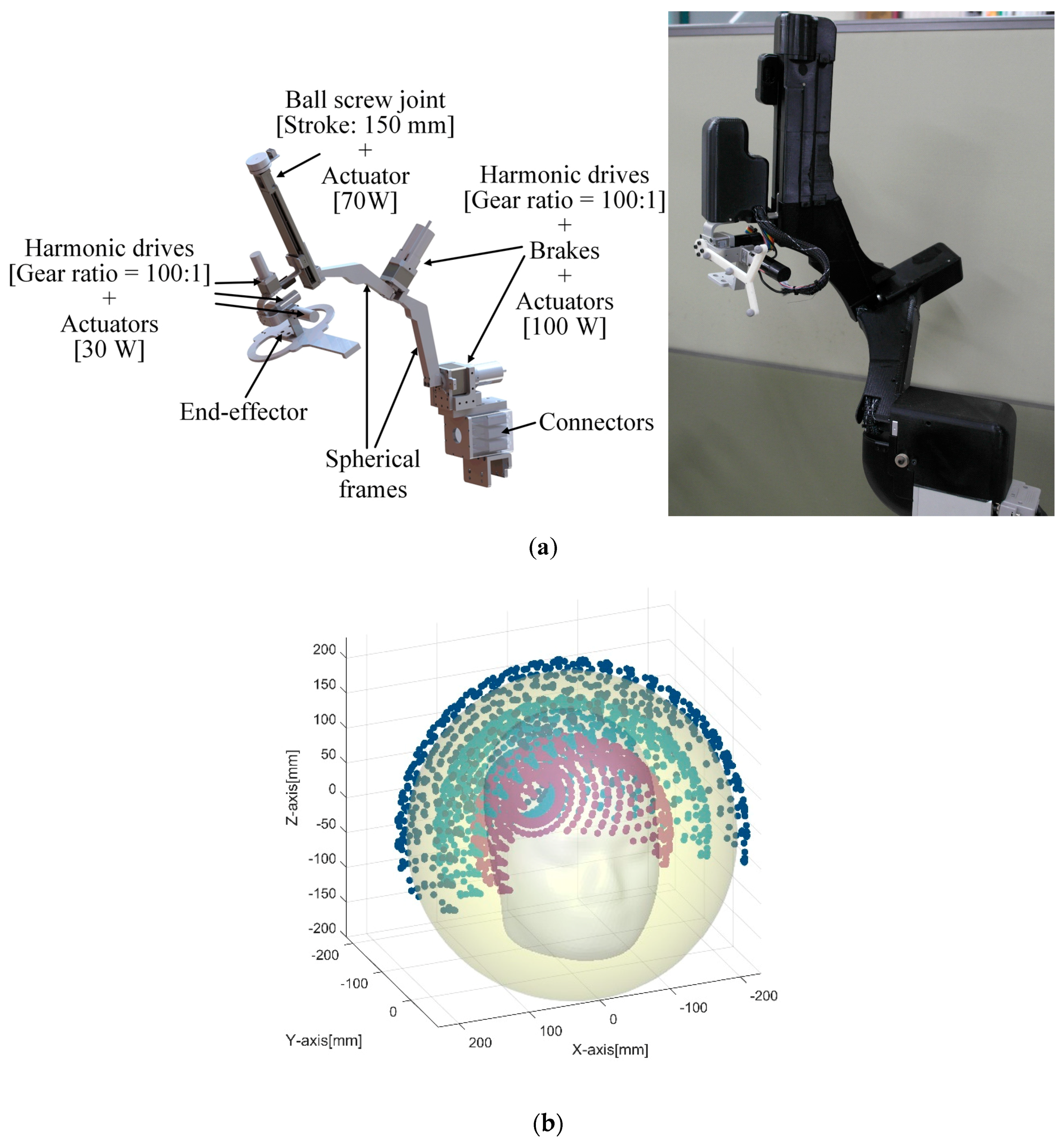
The robotic positioning device was manufactured, as shown in Figure 4. All revolute joints in the device are built with the combination of a harmonic drive, an incremental encoder, a proximal sensor, and an actuator. The gear ratios of all harmonic drives are 100:1. The prismatic joint is composed of a ball screw joint and an actuator. The pitch of ball screw joint is 1 mm, and its stroke length is 150 mm. The power, nominal speed and nominal torque of the actuators installed on the first and second revolute joints from the ground are 100 W, 4390 rpm and 222 mNm, respectively. Those of the actuators at the prismatic joint and the last three revolute joints are 70 W, 4860 rpm, and 128 mNm and 30 W, 2940 rpm, and 54.8 mNm, respectively. In addition, the first and second joints are equipped with power-off braking systems to cope with emergencies. The weight of the final positioning device is about 15 kg.
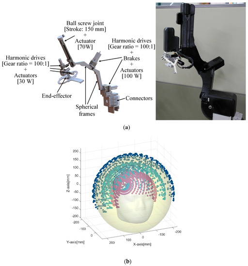
Figure 4.
(a) 3D-model of the spherical robotic positioning device and prototype with enclosure, (b) workspace of the device in given conditions.
The workspace of the proposed device is shown in Figure 4b under conditions in which the last three revolute joints are fixed and the prismatic joint is moved between 0 mm and 100 mm from the initial position.
3.3. Control and Motion Compensation
In this study, the robot was controlled using two methods according to the experiment. In the experiment to measure the repeatability of the robot, open-loop control was used to command the robot in the joint space through the inverse kinematics when the position of the target was determined by the Cartesian coordinate system. In the other two experiments, the robot was controlled using the PBVS method [9] to compensate for unpredicted human movements. The PBVS technique requires a 3D pose estimation process, but the controller used in the conventional Cartesian coordinate system can be used as it is. In this study, the marker-based 3D tracking device was used for neuro-navigation. The navigation program delivers the posture information of the end-effector of the robot and the subject’s head by inter-process communication. This tracking device is described in detail along with the coordinate systems in the next section.
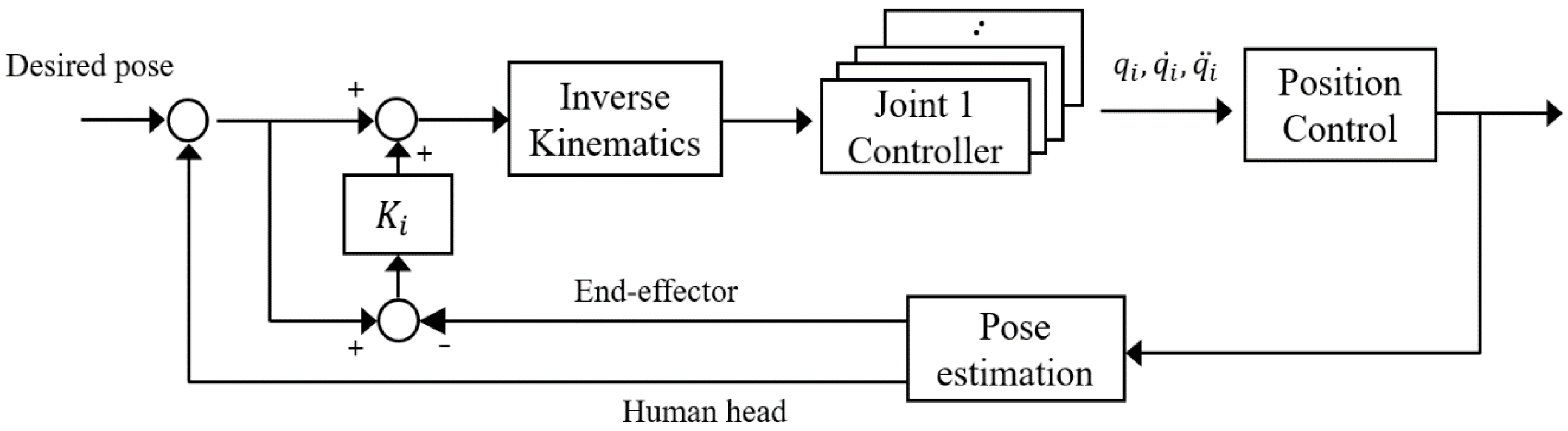
The block diagram of the motion compensation control is given in Figure 5. The coordinate system used for this feedback control is discussed in detail in the next section.
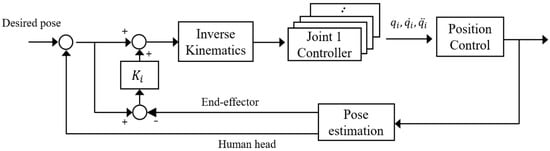
Figure 5.
Block diagram of control and compensation.
The position and orientation errors used for feedback control were defined as follows. The position error ( is defined using the difference between the desired position () and current end-effector position () in Euclidean geometry,
The orientation error depends on the expressions of rotation. The rotation matrix was used for the inverse kinematics of the robot when the target posture was defined in the previous Section 3. The rotation matrix is a matrix that rotates the direction while preserving the length of the arbitrary vector as in Equation (5) and belongs to a special orthogonal group.
The rotation matrix has the advantage that there is no singularity, unlike the Euler angle, but it is difficult to adjust the gain. Other studies have used the error in the rotation matrix and converted it to the angle-axis representation or unit quaternion (Euler parameter) for control [10,11]. We use the rotation matrix to represent the orientation error in the control.
We define a new orientation error () representation using a small-angle approximation of trigonometric functions. If the input angle of the trigonometric function is very small, it can be expressed by approximating and . When the sine function and the cosine function are 14 degrees and 8 degrees, respectively, the error rate due to the approximation is 1%. Therefore, this approximation can be used, because it aims to compensate for the slight movement of the subject. Given the desired orientation (), if the rotation of the end-effector () is determined by the measurement system, the orientation error is:
In Equation (6), the small-angle approximation was applied to the rotation matrix using the ZYX Euler angle. Since small angles are assumed, the second-order and third-order terms are also assumed to be minor enough to be ignored.
This allows us to estimate the rotational error using the component values of the matrix as they are. After multiplying the estimated error by the gain, the final error () is obtained by using the product of the rotation matrix, as in Equation (7). Through this estimation, there is no singularity at any point, which is the advantage of the rotation matrix, and the desired performance can be obtained by adjusting the gain to the orientation error.
The gain is set in consideration of the safety and performance of the experiment, because the faster the speed compensated according to the gain value, the higher the risk of the experiment.
4. Neuro-Navigation System
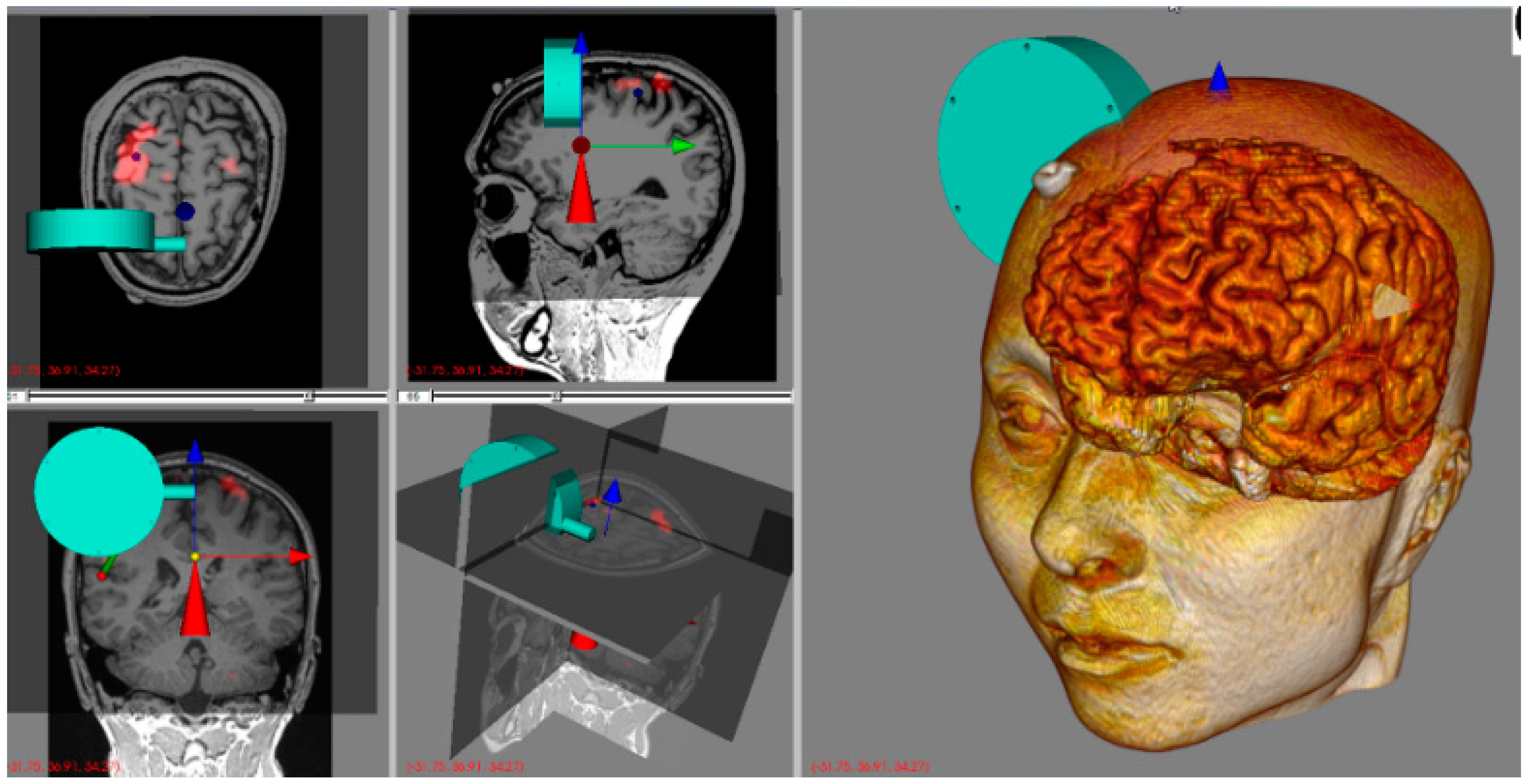
The navigation program was developed based on the Image-Guided Surgery Toolkit [13], which is an open source C++ software library to provide the basic functions for image-guided surgery applications. The basic functions of the toolkit are displaying medical images in three 2-dimensional (2D) planes, e.g., axial, sagittal, and coronal planes, and connecting a tracking system to obtain the 3D information of interesting objects. In addition to these functions, several functions such as communication with a robot program and user interface for target pose assignment were added in the navigation program for controlling the robot (Figure 6). In this section, we explain the coordinate frames and coordinate transform between several coordinate frames because it is essential to realize the main function of the navigation program such as displaying the stimulated pose in the graphic user interface (GUI) and calculating the target posture of the stimulation.
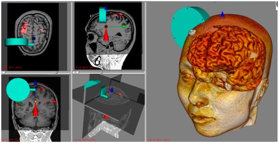
Figure 6.
Graphic user interface (GUI) of navigation program. It displays three 2D windows (axial, sagittal, coronal planes) and two 3D windows. One of 3D windows is combined three 2D planes in the 3D space. In the other 3D window, 3D rendered head and brain model are shown. A transducer model, a red cone, and world coordinate are displayed in every window. The transducer (cyan) is not registered yet.
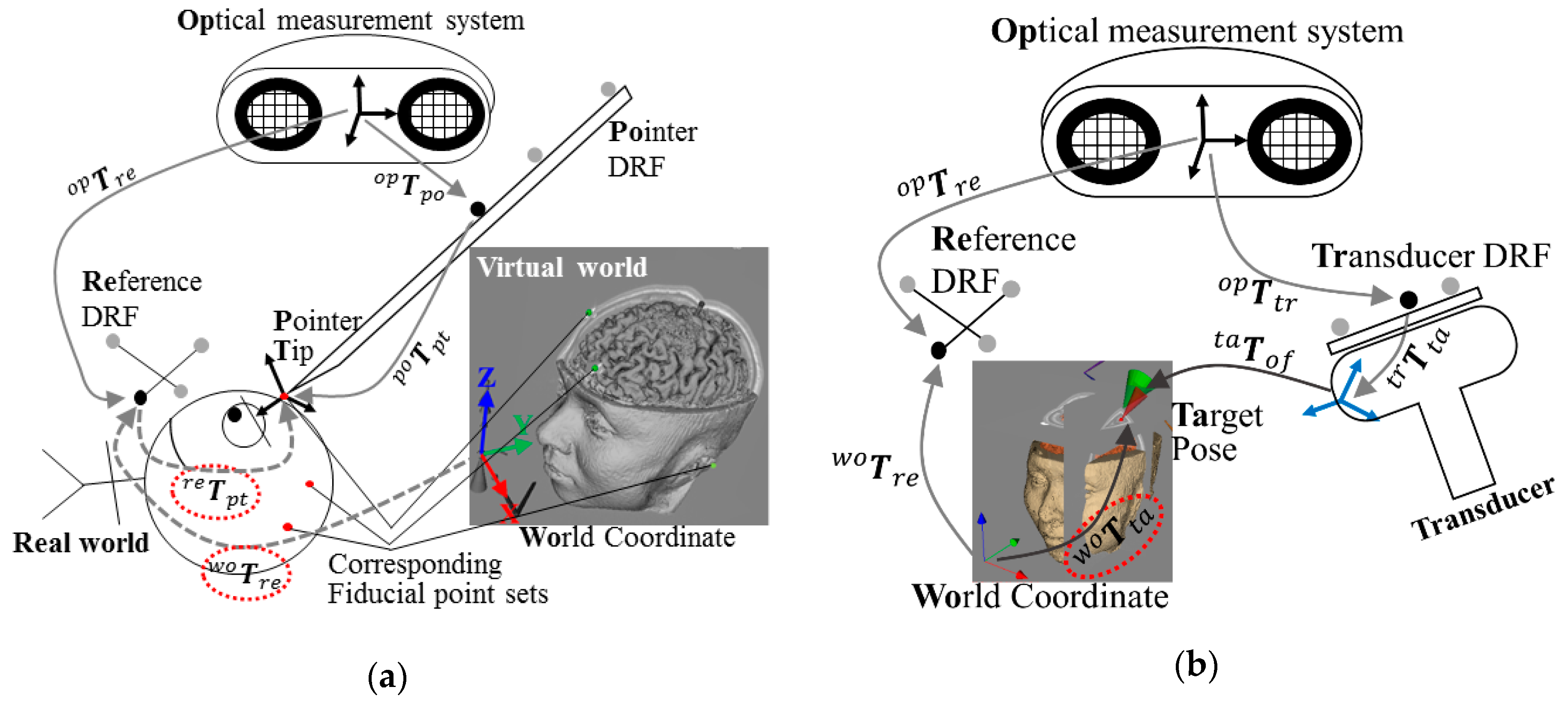
There are three main coordinate frames. Firstly, the world coordinate frame is in the navigation program. MRIs, 3D rendering model, and other graphical objects are attached to this frame. Moreover, users can select the target position and orientation in this frame. Secondly, an optical measurement system (OMS), which is Polaris Spectra infrared camera (Northern Digital Inc., Canada), has its own coordinate frame. Furthermore, dynamic reference frames (DRF) predefined by another program have their own coordinates. Finally, the positioning device has its own coordinate frame. The coordinate frames of the OMS and the positioning robot exist in the real world. The world coordinate frame of the navigation program is in virtual world. For automatic positioning, it is necessary to connect the real and the virtual world. The procedure is called registration.
For the registration, we have to obtain corresponding fiducial points in the navigation program and in the real world as seen in Figure 7a. Usually, the positions of the fiducial points are determined by attaching markers on special points of a subject’s head before doing an MRI. Users can find out the position of the fiducial point on the 2D MRI of the display window; the real-world fiducial points of the subject are pointed by the pointer DRF. When saving the position of the pointer tip, a reference DRF has to be attached to a subject. Because the position is calculated with respect to the reference DRF as follows,
the symbols used in the coordinate transform and Figure 7 are explained in Table 1. In the navigation program, each symbol is composed of position data of vector form and orientation data of quaternion form. With more than three sets of corresponding fiducial points, , that represents the coordinate transform between reference DRF and world coordinate, can be calculated using Horn’s method [15].
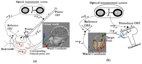
Figure 7.
Two schematic figures represent coordinate transform between several coordinate frames. (a) describes how the pose data of the pointer dynamic reference frame (DRF) with respect to the reference DRF is obtained. For the registration, corresponding fiducial point sets both in the real world and in the GUI are needed. (b) After the registration, the combination of the several coordinate frames to display the transducer in the navigation program is described.

Table 1.
Explanation of coordinate frames used in coordinate transform.
Only after the registration procedure, the transducer model will be visible in the display window. This procedure is described in Figure 7b. Its combination of the coordinate transform is:
By contrast, for the automatic positioning, the navigation program has to give a target pose data to the positioning program. In this case, the target pose with respect to the OMS is transferred as follows:
5. Experiments and Results
5.1. Repeatability Test
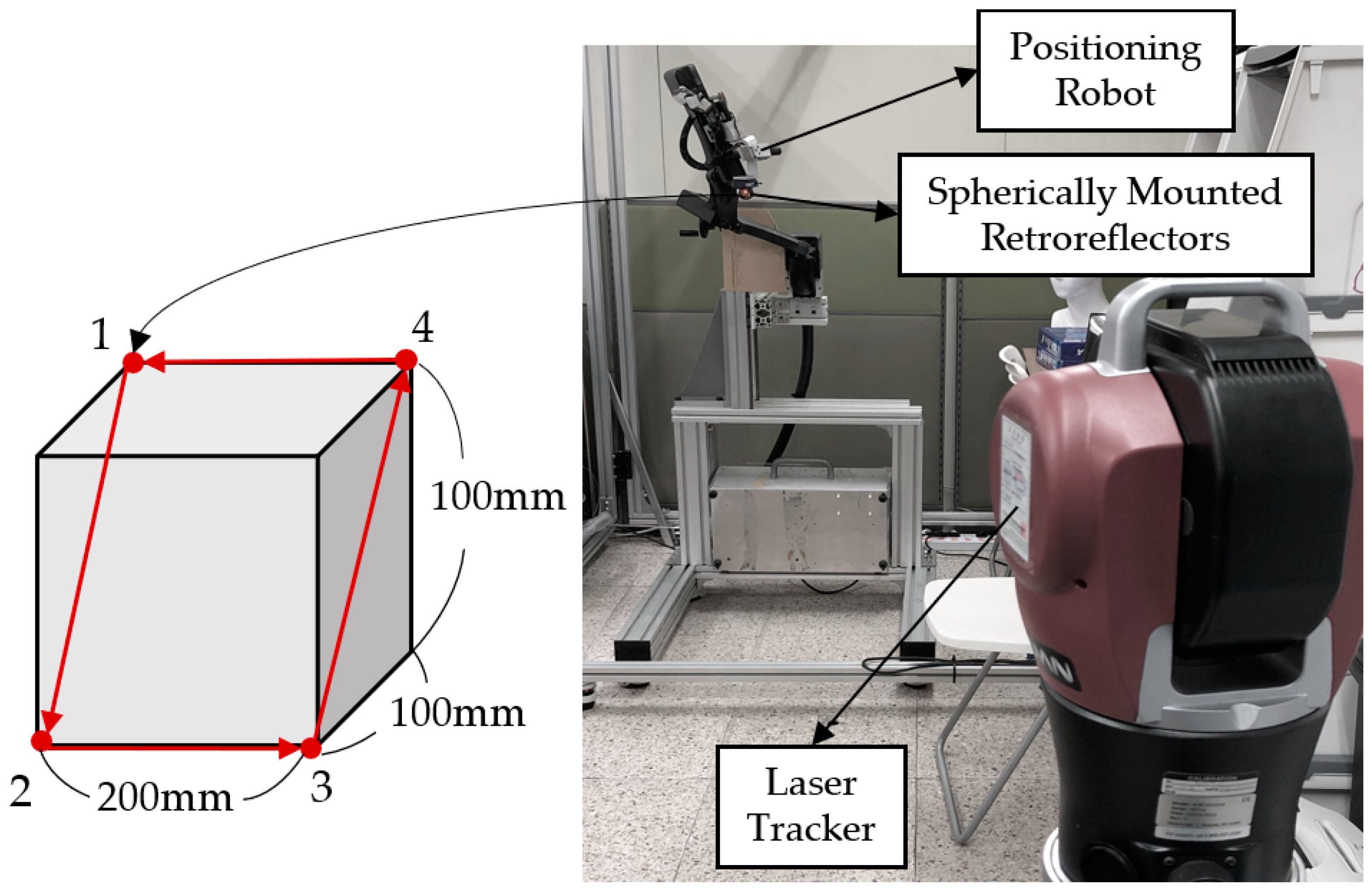
For precise operation of the robot, repeatability experiments are required to verify the same positioning of the same commands in the robot’s workspace. In order to measure the repeatability of the robot, an experimental setup was constructed with reference to ISO 9283. We set the four vertices of the diagonal plane across the test cube with dimensions of 200 mm × 100 mm × 100 mm as the target position, as shown in Figure 8.
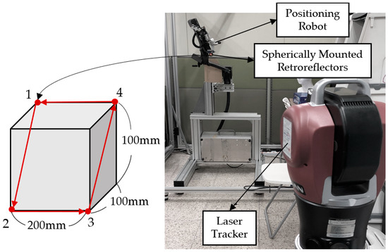
Figure 8.
Setup of repeatability test of robot and test geometry.
In order to avoid the effect of vibration generated when the target point is reached, it started to move to the next target position after a certain time. At each of the four points, 15 measurements were obtained. In the experiment, the position of the end-effector of the robot was measured using a laser tracking system (Radian, API Metrology, USA) with extremely high accuracy. The laser tracking device could accurately estimate the position of API’s spherically mounted retroreflectors (SMRs). In the experimental environment, as shown in Figure 8, the SMR was attached to the end of the robot, and the tracking equipment was constructed about 2 m away from the robot. The system resolution was set to 0.1. We used this instrument only for this measurement test because the robot had very small errors. The error between the reference position and the robot’s real position was calculated using Equation (4). The maximum and minimum errors are shown in Table 2. The repeatability of the robot was calculated as 0.0504 mm. This result is similar to the level of repeatability of industrial robots [16,17]. The OMS introduced in the previous section is to be used as a sensor for tracking objects in other brain stimulation experiments. The OMS has a resolution of a few sub-millimeters which is low resolution compared to the laser tracking system, but that resolution is sufficient for brain stimulation. In this sense, the OMS is an optimal and cost-effective tracking sensor in real clinical situations.
Table 2.
Result of repeatability experiment (unit: mm).
5.2. Regulation and Motion-Compensation Tests
Since the end-effector inevitably contains errors due to both kinematic and non-kinematic factors, there should be errors in the final pose when the robot is controlled by open-loop control. Therefore, it is necessary to perform a process of optimizing a link parameter for a desired area through robot calibration. With this calibration procedure, it is also required to employ a feedback control using an external measuring device to further minimize the final errors.
If the subject is stationary throughout the entire stimulation session, it is possible to reduce the error only by estimating the current pose of the robot. However, this is not the case because the subject cannot immobilize his/her head for a long time. The brain stimulation is usually performed repetitively in clinical situations, with each session lasting several minutes. Therefore, the subject is highly likely to move. We needed to track this movement. Thus, a DRF was attached to the head for tracking.
Firstly, we performed regulation task. We gave three different target postures to the robot and estimated the error at each posture at steady state. Secondly, we performed a head motion compensation task. To verify the motion compensation performance, the subject intentionally generated small movements while the target pose was specified in the navigation program and the robot was in feedback control. For safety, control stopped when the DRF became invisible or the distance between the robot DRF and the head DRF exceeded 300 mm. In the experiment, the tracking device introduced in Section 4 reported the position and orientation of several DRFs with a sampling rate of 30 Hz. The control period of the whole system was set to 35 ms.
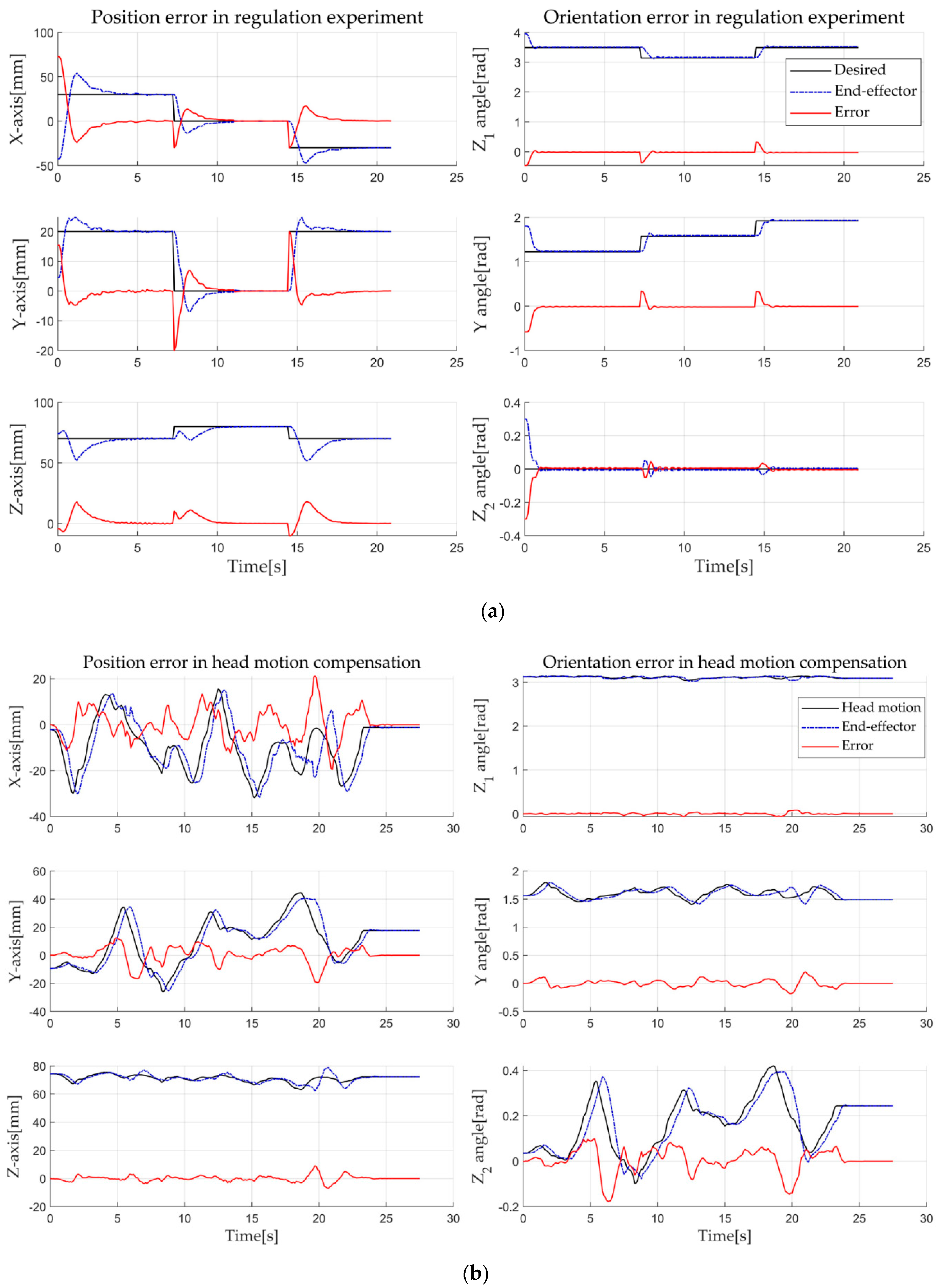
Figure 9 shows the results: a is the result when three different static target postures were given, and b is the result for head motion compensation. The black lines are corrected target postures obtained through the DRF, and the blue dot-dash (-.) lines are the poses of the end-effector obtained through the tracking system. Moreover, the red lines represent error graphs for position and orientation. The position error () is expressed by the XYZ-coordinate using Equation (4), and the orientation error (’) is calculated by using the ZYZ Euler angle. We selected the ZYZ Euler angle because it is more intuitive than other representations.
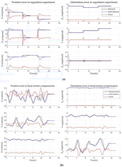
Figure 9.
Regulation and motion compensation experiment of robotic system; (a) is the result when three different static target postures were given, and (b) is the result for head motion compensation.
The regulation task shows that the position errors at steady state are 0.264 mm, 0.047 mm, and 0.072 mm, respectively. Orientation errors were less than 0.04 radian at all three postures (Figure 9a). This accuracy is thought to be sufficient for TMS brain stimulation because TMS targeting accuracy is more than a few millimeters. For motion compensation task, as shown in Figure 9b, the end-effector follows the subject’s head, compensating the error, and finally, the error also becomes almost zero when the subject stops moving. The error seems to be high in particular when the head speed is high. This is because we set the velocity limitation of the robot for safety. The control goal is to remove the error when the target is stationary.
5.3. Repeated Response Experiment of Brain Stimulation
5.3.1. Subjects
Five healthy participants (age: mean = 31, standard deviation (SD) = 5.2, range = 27–39; 5 males) took part in the experiment. All participants were right-handed as determined by an Edinburgh Handedness Inventory [18]. This experiment was conducted with the approval of the Institutional Review Board of Hanyang University Hospital (HYI-18-207-3). All subjects were informed about the risks and monetary rewards of this experiment, and they completed their consent forms before participating in the experiment.
5.3.2. Procedure
In this experiment, we stimulated the primary motor cortex of the brain, specifically, the hand motor area (M1-hand), with the developed robotic system. With the help of the robotic system, we stimulated the same spot repeatedly with a time interval. Here, we used a 10-min interval. Only with navigation, it is very difficult or almost impossible to repeatedly stimulate the same spot with less than a 5-mm error [4]. However, the developed automatic positioning system enabled us to perform this experiment. Here, we used a TMS coil to non-invasively stimulate the brain. It is well known that involuntary movement is induced by the stimulation of the brain’s motor area. The motor area consists of many small areas corresponding to different parts of the body. In this experiment, we stimulated the hand motor area because hand movement is easy to observe and it is generally stimulated to find the standard threshold value in clinical use. To quantify the motion, we measured EMG signals from the hand when we stimulated the brain. The TMS equipment (TAMAS, REMED Co., Republic of Korea) used for the experiment had a figure-of-eight coil (wing diameter: 75 mm).
The test subjects placed their right hands in a comfortable position on a cushion while sitting comfortably in a chair, as shown in Figure 10. In addition, we attached an EMG sensor (Shimmer3 EMG Unit, Shimmer Co., Ireland) to the forearm muscle of the subject with Ag/AgCl surface recording electrodes and detected the MEP to verify the accuracy of the repeated stimulus. MEP is what causes the spinal cord and peripheral muscles to produce neuronal electrical signals by a single pulse stimulation of the brain [19]. Since the position of the motor cortex was slightly different for each subject, the stimulation target position for hand movement and the magnitude of EMG signals should be found and adjusted beforehand. When the optimal site was found through trial and error, the relative posture between the robot and the head was stored. This information was used to stimulate the same place in the next session. A motor threshold is defined as the lowest intensity required to elicit an MEP response of at least 50 amplitude when the TMS is applied to the motor cortex. The motor threshold is the optimal intensity. Therefore, if a different brain area from the target area was stimulated, the MEP response would be smaller.
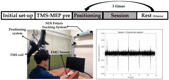
Figure 10.
Procedure and setup of repeated response experiments of brain stimulation.
We first recorded the location where the MEP amplitude was about 50 while stimulating the subject’s brain using the integrated system. This process is represented as TMS-MEP pre in Figure 10. A total of three repetition stimulation sessions were conducted at 10-min intervals per session. Between sessions, the subjects were allowed to leave the chair and take a rest in the room. Subjects were stimulated with the same intensity in all sessions, and the intensity was different for each subject. When the positioning error dropped below 0.9 mm through motion compensation control, we let the stimulation occur. Stimulation was conducted five times per session. The interval in a session was about three seconds. This experiment was a single-blind test. The subjects were unaware of this cycle.
5.3.3. Results and Discussion
The amplitudes of the MEPs differed from person to person. The averages and standard deviations of the MEPs of the five stimulations were represented by different colored bar graphs for each session, as shown in Figure 11a.
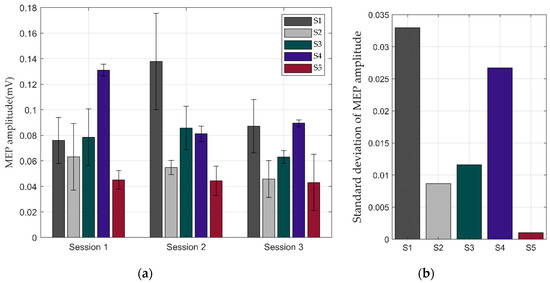
Figure 11.
Result of repeated response experiments thorough stimulation of motor cortex using the integrated system: (a) averages of motion-evoked potentials (MEPs) when each subject was stimulated five times; (b) standard deviations of MEPs in three sessions.
In this experiment, we focused on the repetitive response of motion stimulated by TMS. The repeatable MEP response indirectly verified the repeatable precise position control of the TMS coil on the movable subject’s head. In Figure 11b, the low standard deviation of the MEPs in the three sessions means that the accuracy of robot was good enough to evoke the same responses. The standard deviation of the MEP amplitudes of S5 was very small, indicating that almost the same areas was stimulated in each session even though the subject had been away for a while at a time interval. Meanwhile, S1 and S4 showed slightly higher standard deviations compared to the other subjects, meaning that there was likely more position error. In all cases, however, we concluded that the position error in this experiment was small enough to evoke similar responses, because we cannot expect any MEP response when the position error is large.
This experiment was conducted to show the usefulness of our system as an experimental brain stimulation system. In the future, we plan to conduct neurological brain stimulation research using this automatic positioning system.
6. Conclusions
TMS, one of the non-invasive brain stimulation methods, has become popular in neurotherapy. For clinical use, it is required to achieve high accuracy, repeatability, and to maintain its posture during the positioning of the transducer. To improve the curative effectiveness of treatments using non-invasive brain stimulation, we developed a new robotic positioning device and a neuro-navigation system.
The positioning device has a 6-DOF serial manipulator with a payload of 2 kg. It was developed as a serial mechanism with a RRPRRR chains. In particular, the spherical configuration of the device improves safety and efficiency of movement for brain stimulation tasks. To overcome disadvantages such as deflection and vibration of the positioning device, the thicknesses and shapes of the spherical frames were decided using FEM. By developing the robotic positioning device, the technical functions such as precise positioning, repeatability and motion compensation are achieved. We used feedback control and PBVS to compensate for the unpredictable motion of a subject. A neuro-navigation system was also developed for tracking the stimulator and the subject’s head, and for accepting and delivering the robot control information, such as the target stimulation position in the medical image coordinates.
The experimental results show that the robotic positioning device has high repeatability, 0.050 mm, up to the level of commercial industrial robots. Motion compensation was implemented and verified through experiments. The compensation could be performed more quickly by adjusting control parameters such as feedback gains, but it was set not to be fast for safety reasons. The efficiency of the overall system in real brain stimulation situation was verified through the experiment in which a similar MEP response was obtained repetitively by stimulating the same brain motor area with considerable time interval.
In future work, we plan to collaborate with neuroscientists on a neuromodulation study with the developed system. We expect that the developed precise positioning and repeatability function will enable us to perform experiments that were impossible or very difficult to do in the past.
Author Contributions
Conceptualization, H.S. and S.L.; Methodology, W.R.; Software, H.S. and S.C.; Formal analysis, W.R.; Investigation, H.S., W.R. and S.C.; Writing—original draft preparation, H.S., W.R. and S.C.; Supervision, S.L.; Project administration, S.L.; Writing—review and editing, W.Y. and S.L.
Funding
This work was supported by the National Research Foundation of Korea (NRF) grant funded by the Korea government (MSIT) (No. 2012M3A6A3055694). This work was also supported by the Technology Innovation Program (or Industrial Strategic Technology Development Program) (20001856, Development of robotic work control technology capable of grasping and manipulating various objects in everyday life environment based on multimodal recognition and using tools) funded by the Ministry of Trade, Industry & Energy (MOTIE, Korea).
Conflicts of Interest
The authors declare no conflict of interest.
References
- Barker, A.T.; Jalinous, R.; Freeston, I.L. Noninvasive magnetic stimulation of human motor cortex. Lancet 1985, 325, 1106–1107. [Google Scholar] [CrossRef]
- Laakso, I.; Hirata, A.; Ugawa, Y. Effects of coil orientation on the electric field induced by TMS over the hand motor area. Phys. Med. Biol. 2013, 59, 203. [Google Scholar] [CrossRef] [PubMed]
- O’Reardon, J.P. Efficacy and safety of transcranial magnetic stimulation in the acute treatment of major depression: A multisite randomized controlled trial. Biol. Psychiatry 2007, 62, 1208–1216. [Google Scholar] [CrossRef] [PubMed]
- Kim, J.; Lee, S. Development of a wearable robotic positioning system for noninvasive transcranial focused ultrasound stimulation. IEEE/ASME Trans. Mech. 2016, 21, 2284–2293. [Google Scholar] [CrossRef]
- Pheasant, S.; Haslegrave, C.M. Bodyspace: Anthropometry, Ergonomics and the Design of Wor; CRC Press: Boca Raton, FL, USA, 2018. [Google Scholar]
- Lum, M.J.H. Optimization of a spherical mechanism for a minimally invasive surgical robot: Theoretical and experimental approaches. IEEE Trans. Biomed. Eng. 2006, 53, 1440–1445. [Google Scholar] [CrossRef] [PubMed]
- Al Bassit, L.; Poisson, G.; Vieyres, P. Kinematics of a Dedicated 6 DOF Robot for Tele-echography. In Proceedings of the 11th International Conference on Advanced Robotics, Coimbra, Portugal, 30 June–3 July 2003. [Google Scholar]
- Zorn, L. Design and evaluation of a robotic system for transcranial magnetic stimulation. IEEE Trans. Biomed. Eng. 2011, 59, 805–815. [Google Scholar] [CrossRef] [PubMed]
- Wilson, W.; Hulls, C.; Bell, G. Relative end-effector control using Cartesian position based visual servoing. IEEE Trans. Robot. Autom. 1996, 12, 684–696. [Google Scholar] [CrossRef]
- Luh, J.; Walker, M.; Paul, R. Resolved-acceleration control of mechanical manipulators. IEEE Trans. Autom. Control 1980, 25, 468–474. [Google Scholar] [CrossRef]
- Caccavale, F. Resolved-acceleration control of robot manipulators: A critical review with experiments. Robotica 1998, 16, 565–573. [Google Scholar] [CrossRef]
- Takahashi, S.; Vajkoczy, P.; Picht, T. Navigated transcranial magnetic stimulation for mapping the motor cortex in patients with rolandic brain tumors. Neurosurg. Focus 2013, 34, E3. [Google Scholar] [CrossRef] [PubMed]
- Cleary, K.; Cheng, P.; Enquobahrie, A.; Yaniv, Z. IGSTK: The Book; Signature Book Printing: Gaithersburg, MD, USA, 2007. [Google Scholar]
- Iglesias, J.E.; Liu, C.-Y.; Thompson, P.M.; Tu, Z. Robust brain extraction across datasets and comparison with publicly available methods. IEEE Trans. Med. Imaging 2011, 30, 1617–1634. [Google Scholar] [CrossRef] [PubMed]
- Horn, B.K. Closed-form solution of absolute orientation using unit quaternions. JOSA A 1987, 4, 629–642. [Google Scholar] [CrossRef]
- Slamani, M.; Nubiola, A.; Bonev, I. Assessment of the positioning performance of an industrial robot. Ind. Robot. 2012, 39, 57–68. [Google Scholar] [CrossRef]
- Nubiola, A.; Bonev, I.A. Absolute calibration of an ABB IRB 1600 robot using a laser tracker. Robot. Comput. Integr. Manuf. 2013, 29, 236–245. [Google Scholar] [CrossRef]
- Oldfield, R.C. The assessment and analysis of handedness: The Edinburgh inventory. Neuropsychologia 1971, 9, 97–113. [Google Scholar] [CrossRef]
- Rossini, P.M. Applications of magnetic cortical stimulation. Electroencephalogr. Clin. Neurophysiol. Suppl. 1999, 52, 171–185. [Google Scholar] [PubMed]


© 2019 by the authors. Licensee MDPI, Basel, Switzerland. This article is an open access article distributed under the terms and conditions of the Creative Commons Attribution (CC BY) license (http://creativecommons.org/licenses/by/4.0/).