Article

Application of a Propeller-Based Air Propulsion System to the Land-Based Holonomic Vehicle

1
Institute for Future, Qingdao University, Qingdao 266071, China
2
Micro/Nano Technology Center, Tokai University, 4-4-1 Kitakaname, Hiratsuka-city 259-1292, Japan
3
Department of Mechanical Engineering, School of Engineering, The University of Tokyo, 7-3-1 Hongo, Bunkyo-ku, Tokyo 113-0033, Japan
*
Author to whom correspondence should be addressed.
Appl. Sci. 2019, 9(21), 4657; https://doi.org/10.3390/app9214657
Submission received: 10 September 2019 / Revised: 18 October 2019 / Accepted: 29 October 2019 / Published: 1 November 2019
(This article belongs to the Section Nanotechnology and Applied Nanosciences)

Abstract

:
Holonomic vehicles with wheels such as ball wheels can move in any direction without rotating. For such a system, more driving motors and precise transmission mechanisms are necessary, which makes the control and fabrication complicated. This paper aims to present the design and construction of a novel holonomic mechanism to simplify the system. Air-based propulsion was applied to a land-based holonomic vehicle. A prototype with three roller balls was developed with a propeller for the propulsion of a triangular holonomic vehicle. Only two motors were applied, one for propeller rotation and the other for the adjustment of the angle of thrust. For the establishment of the methodology, the data, including propeller size, rotation per minute, velocity, thrust, efficiency, etc., were measured or calculated. The prototype can move at a velocity of approximate 0.558 m/s with an efficiency of 18.55%. Simulation results showed that with the increase of propulsion efficiency, the velocity can achieve more than 5 m/s if the efficiency is 70%. This study is the first attempt to apply air-based propulsion to a land-based holonomic vehicle. Further, the construction method is simple and can satisfy the accuracy requirement. This design method, therefore, will contribute to the application of holonomic vehicles due to the realization of holonomic functionality and simplicity.

1. Introduction

In contrast to non-holonomic vehicles, such as regular automobiles, a holonomic vehicle can move in any direction without rotating its body. This extra mobility gives the holonomic vehicle an advantage over non-holonomic vehicles. A holonomic vehicle is ideal for narrow or small working environments, where turning the vehicle is hard or impossible. Holonomic vehicles are also useful when performing difficult driving maneuvers, for example, parallel parking is much easier to perform in a holonomic vehicle than in a standard non-holonomic vehicle. Because of the usefulness of holonomic and Omni-directional vehicles, engineers over the years have developed unique ways to make vehicles holonomic.
Because of the advantages of the holonomic vehicle, it has been applied under various conditions, as follows. One type of holonomic vehicle is called the power caster vehicle (PCV). The PCV’s design basically looks like a powered office chair. The PCV is a stable holonomic vehicle that can smoothly navigate all of the usual indoor obstacles [1]. It was successfully integrated with the Programmable Universal Machine for Assembly, or Programmable Universal Manipulation Arm (PUMA) robotic arm in Nomadic Technologies XR4000 robot [2]. To help the physically challenged, a holonomic wheelchair with a ball and wheel mechanism was created [3,4].
The OmniMate is a holonomic vehicle that was created for hazardous environments. It requires few external corrections because it uses an internal position control correction device that allows it to correct for bumps and other floor irregularities [5,6].
There have been several types of wheels developed for the application in holonomic vehicles, as follows. One vehicle design that allows for holonomic movement incorporates Mecanum wheels. Mecanum wheels consist of a ring of angled periphery rollers. With varying wheel directions and speeds, the combination of forces produced allow the vehicle to move in any direction [7,8]. Another wheel design manufactured for holonomic vehicles is made up of several smaller wheels attached perpendicularly along the periphery of the main wheel [9]. A frequently used design for mobile robots is a three-wheel design, with wheels arranged at the vertices of an equilateral triangle [10]. An interesting approach to create a holonomic vehicle is in the shape of a sphere. By controlling pendulums that are mounted in the spherical body, the spherical vehicle is able to move in any direction [11]. A different way to use a sphere in a holonomic vehicle is to use it as a tire. A single rider holonomic vehicle was created, using a basketball as a tire, and four force-transfer-mechanisms for movement [12].
Various models for the control of the holonomic movement of land-based vehicles, underwater vehicles, indoor airship or aerial robots, have been explored in previous studies [9,13,14,15]. For holonomic control, each wheel of the holonomic vehicle drives the robot forward and rotates the frame of the robot; this is because the wheels are located on the frame periphery. The number of traction forces which can be obtained is equal to the number of activated motors, and the driving direction and the sum of the resultant forces are calculated from these forces generated by the motors [9]. Therefore, conventional methods used redundant thrusters to realize motion in each direction, which resulted in high weight and costs. In a study by Ehlers et al. on underwater vehicles (SMART-E), all six degrees of freedom (forward/back, left/right, up/down, yaw, roll and pitch) were controlled by using three thrusters [16]. The three thrusters were rotated by a servo motor about 180° around a rotating axis to achieve holonomic 3D movements, and full holonomic propulsion of underwater vehicles was realized based on the mathematical force model used in the work by Rojas [13,16]. The model considered resultant forces generated by the three thrusters, each of which was a linear combination of a horizontal part inside the vehicle’s x-y plane and a vertical part [9,13]. The forces add up and provide a translational and rotational motion for the robot [9,13]. These studies analyzed the forces according to the number of motors activated, and the traction forces were equal to the number of thrusters [9]. Similarly, Valdmanis et al. drove a holonomic airship using six fans, which consisted of DC motors and propellers [14]. These studies suggest that scientists have adopted a propulsion system based on an increasing number of motors and a sum of ≥ 3 thrust forces to drive a holonomic system.
Many holonomic mobile robots are actuated mainly by electromechanical drives with fixed gearing. The efficiency of the drives with fixed gearing degrades as its torque-speed ratios change, although it has been reported that when a continuously variable transmission (CVT) is integrated into the design concept of a vehicle, the weight of the vehicle can be reduced and its performance can be increased [17]. However, it is known that CVT has disadvantages, such as low efficiency and high maintenance and repair costs because of the specific components and manufacturing process of a CVT vehicle [18,19,20].
As mentioned above, most of the previous studies on mobile robotics focused on the design of the degree of freedom (DOF) of the driving wheels, which were driven directly by the attached motors [21,22]. Based on the consideration, types of omnidirectional wheels were designed to increase the DOF, like 1 DOF to 2 DOF. The problem is the design of the propulsion system. The traditional system drives one wheel directly by a coupled motor and the motor controlled one by one [22,23,24], which made the control and fabrication of the system complicated. Moreover, the increased number of motors leads to heavy weight and high cost; therefore, the methods cannot fully apply the advantages of ball-based wheels. In this paper, a simple method is developed to effectively improve the performance of the holonomic vehicle with a ball based wheel, which will promote the application of the holonomic vehicle.

2. Materials and Methods

2.1. Specification Requirements

Universal and Mecanum wheels vibrate while the robot mobiles, due to the discontinuous contact points of the wheels. On the other hand, ball-based wheels run without any vibrations because the contact points are continuous [25]. Therefore, ball-based wheels were chosen in this study. The specification requirements are as the following:
  • Omnidirectional driving: Realization of propulsion in any direction without the rotation of the vehicle body with ball-based wheels. This function can be fulfilled by increasing the motor number, but it will make the system complicated. So a breakthrough in the driving method is necessary.
  • Simplicity: Simple structure and components comparable to nonholonomic systems are important for practical use. Casual control of the movement path without any path planning. In other words, the realization of omnidirectional mobility and effective control do not act upon the premise of an increased motor number and structural complication.
The two requirements are conflicting when using conventional design, and therefore a new methodology for the conduction of holonomic motion is highly required.

2.2. Concept and Experimental Design

As shown in Figure 1, the holonomic vehicle designed in this research is incorporated with a propulsion system which has not currently been used for land-based holonomic vehicles [26]. The air-propulsion system is basically driven by a propeller that is attached to a powerful direct current (DC) motor amounted to a continuous-rotation servo motor. The frame on which the servo motor attached is seated on free-rolling wheels. This is because the servo motor is able to rotate 360 degrees, which allows the air-propulsion system to move freely and push the vehicle in all directions.
Small propellers for Unmanned Aerial Vehicles (UAVs) or Micro Aerial Vehicles (MAVs) are commercially available [27]. Small propeller performance is different from that of a large-sized propeller because the operating Reynolds number of airflow is different [27]. One of the differences of the application of propellers between aircraft and land-based vehicles is that the relationship between engine power and body weight/drag force is considered in the case of aircraft, but for a land-based vehicle, the friction between the roller and land surface should be calculated. Based on the concept, a complicated calculation of thrust force is not required, because there is only one force for driving. The mathematical models of thrust, velocity and efficiency of the propeller can be adopted from the model of the aviation industry, as shown in the Section 2.4.

2.3. Components

The motor used to drive the propeller is an electric DC motor (Maxon Motor Inc., Fall River, MA, USA). The motor is powered by a 9.6 volt nickel-cadmium (NiCd) rechargeable battery pack (Figure 1d).
The propeller attached to the motor was purchased (RAYCorp 6045 6 × 4.5 Bullnose Propellers, RAYcorp Inc., Tinley Park, IL, USA) (Figure 1e). The basic data, such as the relationship between rotation velocity and thrust, was not available before experiments.
The DC motor is mounted to a sub-frame. This sub-frame will be mounted on top of a continues-rotation servo motor (Figure 1c). This will allow the sub-frame to rotate 360 degrees with precision (0.1 degrees of precision).
One problem that applies to mobile robots, including ones that are holonomic, is the localization of the vehicle with respect to the environment and map building. Using optical triangulation information from isometric and optical sensors, the robot can find the optimal exploratory path. This can be used for robotic rovers used in planetary exploration missions, which would have to move in an unknown environment [28]. Therefore, to characterize this function to the system, the steel frame of the vehicle in this study was created in a triangular form. This frame was constructed with MECCANO® ERECTOR® pieces (Erector Inc., Pleasant Hill, IA, USA). The ERECTOR® pieces have predrilled holes in them, and are attached to each other with nuts and bolts. The triangular frame sits on three roller balls (Erector Inc., USA). The roller balls allow for an instantaneous change of direction, and permit the vehicle to freely move with 360 degrees of freedom. The three wheels are bolted to the bottom of the three endpoints of the triangular-shaped frame.
In a previous study, holonomic distribution control was used to plan a reactionless path to the desired point in Cartesian space. An example where this is needed is on manipulators that are attached to spacecraft. The manipulator’s motion can disturb the altitude and position of a spacecraft [29]. The sensor-control-interface (SCI) board with two neuromorphic sensors was used to control a holonomic robot. The SCI board provides a simple and flexible interface that works for various setups. It allows us to set up and operate small systems with neuromorphic sensors quickly and easily [30]. In this study, the aim is to develop a basic system to confirm the probability of the realization of the design concept, so manual control was applied to simplify the system. Attached to the center of the frame is the microcontroller board (Figure 1b) (Model#555-28188, Parallax BASIC Stamp Inc., Rocklin, CA, USA). The BASIC Stamp is a microcontroller that allows the holonomic vehicle to be remotely controlled.
By using a standard universal television remote the servo and the DC motor can be operated with 0.1 degrees of precision. By using a two relay set up, the motor can run forward or reverse. This allows the vehicle to change directions without needing to rotate the direction of the motor 360 degrees. Mounted below the microcontroller is the 9.6 volt NiCd rechargeable battery pack.

2.4. Equations and Analytical Methods

The methods for evaluating the propulsion for non-holonomic vehicles, manned or unmanned aircraft systems and underwater vehicles have been extensively studied [16,31,32,33,34]. To control the aircraft systems, the power needed for the aircraft to maintain certain airspeed and altitude (power required) and power produced by the engine (power available) was calculated [31]. Further, the relationship between the Maximum Takeoff Weight of air vehicles and engine power, thrust generated by propeller, flight speed, airspeed and propeller efficiency, were designed and verified [31]. The followings were used to evaluate the performance of the propeller driven by the motor, partially adopted from the standard procedures available in aviation industry. In this study, to demonstrate the method and process for the evaluation, vehicle motion on a wooden surface was taken as an example.

2.4.1. Power Required and Power Available

In the aviation industry, the power needed for maintaining a constant airspeed and altitude is calculated based on the drag force produced by the airframe and the airflow. For the prototype used in this study, the friction between the roller and the ground was supposed to be the main drag force, according to a theory used in a study on mobile robotic dynamics with friction [35]. Therefore, the static friction between the steel roller ball and ground surface is of a great concern, since most frictional loss is associated with static friction. Once the vehicle starts to move, the static friction shifts to dynamic friction, which mainly depends on the frictional performance of the roller balls.
The static friction between the steel roller ball and the wooden surface was calculated using the following equation [35].
F r = μ . N
where F r is the resistive force of friction, μ is the coefficient of friction for the two surfaces at zero velocity, and N is the perpendicular force pushing the two objects together. In the study, N is the weight of the prototype (Table 1). After the vehicle was set in motion, the friction coefficient μ was the Coulomb friction at non-zero velocities (Table 1) [35].
In this study, calculation of the driving direction and the sum of forces is not required as conventional control methods of holonomic vehicles [13], because the holonomic movement was realized by only one force, a simple control model.
The Power of the motor can be obtained by knowing the current and voltage of the DC motor (Table 1).
P = V . I
where P is the power, V is the potential difference, and I is the current.

2.4.2. Relationship among Thrust Force, Velocity and the Propulsion Power

The mathematical model here was adopted from two previous studies on propellers used for the propulsion of an aircraft [31,36]. Exemplary, the thrust force is measured as a function of the propulsion (engine) power.
Airplane velocity/airspeed is a parameter for the propulsion system of an aircraft. Here, the velocity of the robot was calculated according to time traveled and the measured displacement from the following equation.
Δ x = u . Δ t + 1 2 . a . Δ t 2
where Δ x is the displacement, u is the initial velocity, Δ t is the time interval and a is the acceleration. Measured data and calculation results of the prototype according to the formula are shown in Table 1 and Table 2.
To find the relationship between robot velocity, propeller efficiency and motor power, the following formula was used [36]:
ν = η . ( 2. P π . ρ . D 2 . ( 1 η ) ) 1 3
where P is the motor power, D is propeller diameter, ν is the velocity of incoming flow, η is the propeller efficiency, and ρ is the density of the fluid in the calculation. The density of air is ρ a i r = 1.225 kg/m3.
The thrust of a propeller depends on the volume of air accelerated per time unit and on the density of the medium. Based on the momentum considerations, it can be expressed as [36]:
T = π 4 . D 2 . ( ν + Δ ν 2 ) . ρ . Δ ν
where T is the thrust, D is the propeller diameter, ν is the velocity of incoming flow (Equation (4)), Δ ν is the additional velocity by the propeller and ρ is the density of the fluid.
From Equations (4) and (5), the relationship between thrust force and engine power can be established.
In this study, only one propeller (RAYCorp 6,045 6 × 4.5 Bullnose Propellers, RAYcorp Inc., Tinley Park, IL, USA) was applied in experiments to confirm the concept. To illustrate the feasibility of the mathematical model, the results in Table 1 and Table 2 were used to confirm the consistency of the measured data and calculation results shown in Table 4. The results in Table 4 were calculated using Equations (4) and (5) when assuming that a series of propeller efficiency from 0% to 100% can be realized, which are also shown in Figure 4.

2.4.3. Efficiency of the Prototype

Different from the efficiency of the propeller system (refer to Equation (4)), the efficiency of the prototype is defined as the ratio of available power to the engine power. The available power can be found by knowing the thrust of the propeller system and the velocity of the incoming flow [36].
η = P a P e n g i n e = T ν P e n g i n e
where Pa is the available power, P e n g i n e is the motor or engine power, T is the thrust, and ν is the velocity of the incoming flow.

3. Results

Before the performance tests were conducted, the diameter of the propeller was measured and the finished prototype was weighted. In addition, the static and rolling friction forces were calculated (Table 1 and Table 2).
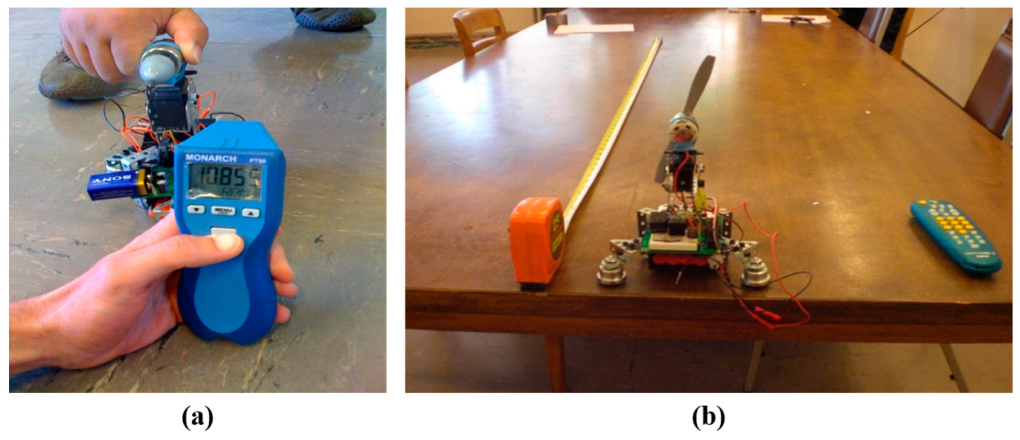
In the first test, the RPM of the propeller was measured by using a handheld tachometer (Figure 2a). The measurements were taken at the propeller’s maximum RPM and at the minimum RPM needed to start the vehicle in motion. The results of the tests gave a range of 8000 to 13,000 RPMs. With these results, the range of efficiency was determined.
In the second test, the velocity of the vehicle was measured (Figure 2b). Using a stopwatch and a measuring tape, the amount of time needed for the vehicle to travel five feet (1.524 m) is recorded, and the velocity can be easily calculated. Two tests were performed on the linoleum floor and three tests on a wooden tabletop. The average time was 2.73 s, giving a speed of 0.558 m/s (Table 3).
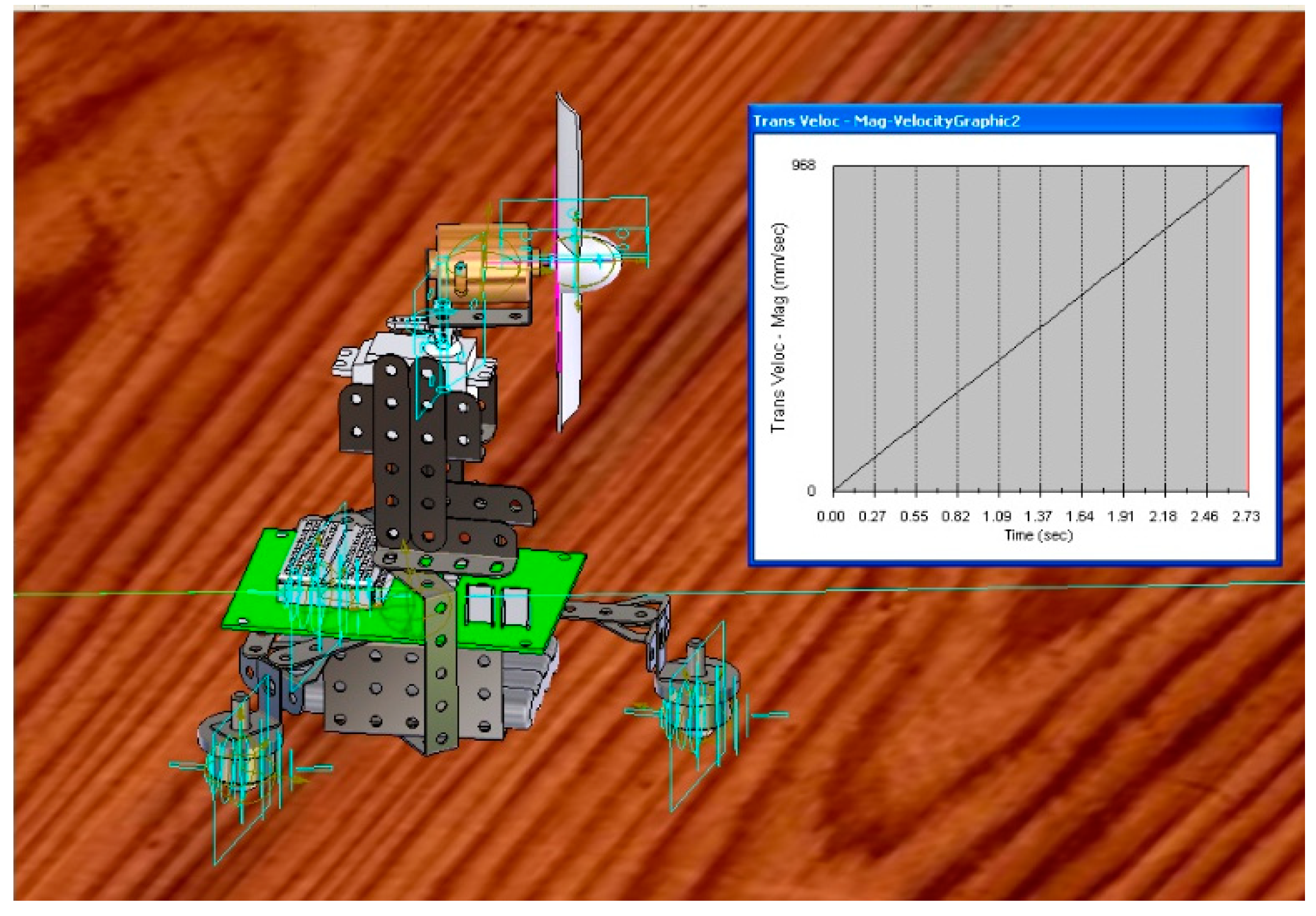
The third test was done in SolidWorks Motion, which is a 3-D CAD program that allows us to simulate the design’s motion (Figure 3). A constant force was applied to the motor to represent the force that the propeller would normally provide. With each test, the force that was applied to the motor was changed, and we found the corresponding velocity of the vehicle at 2.73 s. With these results, the velocity change with respect to efficiency can be compared to that given by hand calculations (Table 4).
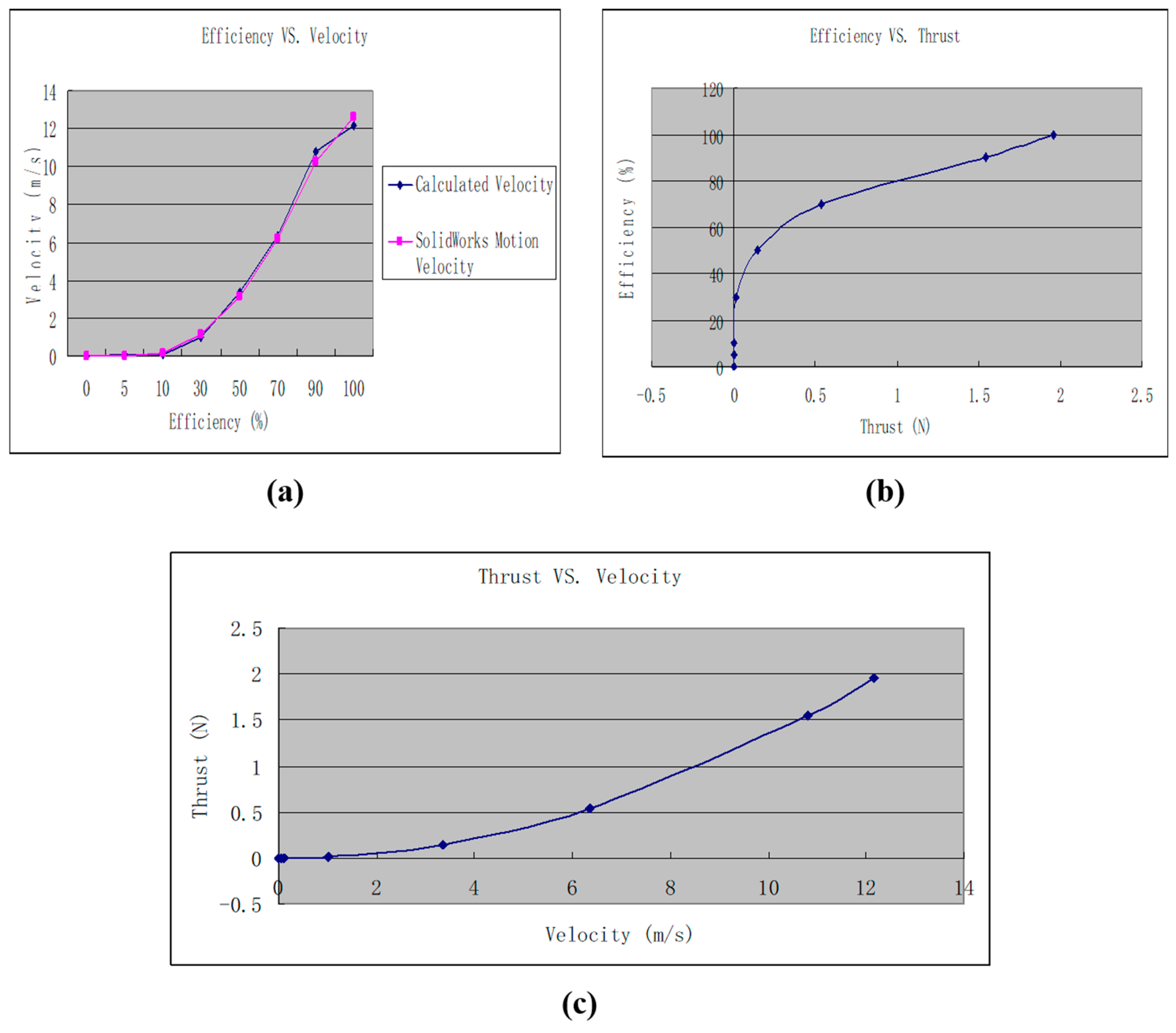
The efficiency and thrust of the propeller system determines the velocity of the vehicle. To better understand the relationship between the efficiency of the propeller system, thrust of the propeller system and velocity of the vehicle, Figure 4a,b have been created. The maximum efficiency of the propeller system is assumed to be 100%. By setting the efficiency of the propeller system into eight efficiency levels within the range of 0% to 100%, the corresponding values of the thrust can be calculated from Equation (4). The average error was 12.02% when comparing the velocity between the experimental result and the one from the simulation using SolidWorks. The results suggest that using SolidWorks Motion is an alternative way to find the velocity of a vehicle.
As calculated in Table 2, the actual velocity is 0.558 m/s. As shown in Figure 2, the calculated velocity is approximately equal to the actual velocity. As shown in Figure 4c, the velocity of the vehicle is directly proportional to the thrust of the propeller system. Therefore, with more thrust of the propeller system, the velocity of the prototype will increase.
The highest discrepancy between the two results was obtained at the low velocities of the vehicle. At low velocities, the static friction plays a major role in motion. That is the reason for a high error percentage between the SolidWorks Motion results and those theoretical velocity calculations in the beginning (error = 41.6%). As the velocity increased, the error percentage between SolidWorks Motion and theoretical Calculations decreased significantly, because the static friction is changed to rolling friction (error = 3.5%).
Figure 4 contains the calculated velocity of the vehicle and SolidWorks Motion velocity, and shows a close relationship between calculated and simulated results.
To understand the relationship between the thrust and velocity of the prototype, Figure 4c is applied. The thrust of the propeller system and velocity of the vehicle are in a direct proportional relation. The more the thrust, the faster the vehicle moves.
Finally, the velocity of incoming flow is measured to be 2.722 m/s. Using Equations (5) and (6), the actual efficiency of the whole vehicle is found to be 18.55%.

4. Discussion

In this study, the performance of a propeller on the holonomic vehicle is evaluated by both the performance experiments and the FEA simulation. To the current knowledge, this is the first attempt to evaluate the efficiency of propeller-induced propulsion ball-based wheels. Ball-based wheels indeed have many advantages over the Mecanum wheel design, such as reduced friction between the wheel and the ground and a higher motion velocity.
Using the conventional method, the design and fabrication of a ball based system must consider details such as the complicated platform velocity kinematic relations, the cooperative work of the motor control system and the position precision of the fabricated three-dimensional structures [22,37]. On the other hand, based on the design concept, not all complicated and basic mechanical design of components is necessary. Alternatively, a selection of commercially-available parts such as motors, propellers, ball wheels, etc., may be enough for the assembly of a holonomic vehicle. It can be said that the design is conceptually simple and therefore easy to manufacture. However, the concept may not be specific for the propulsion of a vehicle with ball-based wheels, but it may be suitable for the Mecanum wheels if only the propulsion method is considered. The universal design concept will thus promote the commercial use of the omnidirectional wheels, the application of which was said to be rarely found in commercial products [38].
From Equations (4) and (5) and Figure 4, it is not coincidental that for an applied propeller, a large efficiency value directly increases the motion velocity, and further increases the thrust exerted on the vehicle. As shown in Table 4, the theoretical velocity calculations confirmed the SolidWorks Motion velocity data. Therefore, the performance of the fabricated system suggests that the propeller is suitable for the holonomic vehicle driving, although the efficiency of the other type of propeller was not investigated. Even so, results from the simulation by SolidWorks supported the effectiveness of the system design. Because the efficiency of the propeller is determinative for the velocity and thrust, a propeller design or a proper propeller selection is crucial to improve the efficiency. Propeller design and selection including parameters such as the propeller diameter and pitch should be based on experimental results such as performance data or a wind tunnel test. Because the basic propeller experimental data is important, Merchant had measured data (Blade number, thrust, torque and revolutions per minute, etc.) of small propellers with a diameter ranging from 6 to 22 inches, and the calculated results showed the efficiency of some propellers [27]. For example, a propeller with an 8.8 inch diameter and 8.75 inch pitch had an efficiency ranging from appropriate 0 to 60% as the Advance ratio (a parameter proportional to wind tunnel speeds and reversely proportional to Revolutions Per Second and Propeller Diameter) increased, and a large-sized propeller with a 12 inch diameter/pitch had a maximum efficiency of approximately 80% [27]. The actual efficiency of this study was 18.55% (Table 2). In the follow-up study, the velocity of the vehicle can be increased by improving the efficiency of the system through enlarging the propeller, and the velocity can be larger than 5 m/s when the efficiency is 70% according to Table 4.
About the prototype developed in this study, there are some points to be improved. First, an improved program was necessary to control the vehicle conveniently and smoothly. In this study, in order to make the control simple and easy to understand, a series of operations of the forward/backward movement of the vehicle/fan were conducted by pushing up to 10 pairs of numbers on the universal television remote. It is obvious that a deeper understanding of the performance data, or a detailed motion plan is required, such as the auto control of the servo together with the DC motor. Further, a collection of sensors for environment detecting can be integrated into the holonomic vehicle, and make the vehicle an automatic mobile robot [39]. Second, it is difficult to make precise movements with the vehicle, because the thrust of propeller is difficult to manipulate immediately after the start of the fan (fan acceleration period), which causes the movement to be imprecise. In this study, for a journey period of 2.73 s, the acceleration time was more than 1 s, according to the measured and calculated data in Table 1 and Table 2. Therefore, to improve the precision of vehicle motion, it is necessary to consider the motion pattern such as the time point to move after the propeller start or the integration of a velocity prediction curve into the control program. Further, maybe a more certain experimental condition is necessary for the measurement of basic performance data, such as the testing of both static and dynamic conditions in a wind tunnel, which was conducted in a study by Brezina et al. [40].
It may be thought that the exposed propeller would be a potential safety issue, and the wind created by the propeller prevents the vehicle from being suitable for indoor use. But a safety improvement can be achieved by adding a cage around the propeller, which can prevent accidental injuries.
Indeed, nowadays several studies have developed an indoor micro air vehicle with propellers by adding a cage around the propeller [41,42,43]. In the future, the servo top with stronger material can be used to reduce the strain acting on it, and this provides more precise movement to the vehicle by using a better servo motor.

5. Conclusions

In this research, an air-based propulsion to land-based holonomic vehicle is designed and its functionality is tested. Currently, the most common method for creating a holonomic vehicle is with the use of Mecanum wheels. However, the new method is to use a propeller as the driving force in the vehicle design and roller balls for the wheels to achieve the maneuverability as a holonomic vehicle.
Using AutoCAD, such as SolidWorks Motion, is an alternative way to find the velocity of a vehicle. As shown in Table 4, the theoretical velocity calculations confirmed the SolidWorks Motion velocity data. The average error was 12.02%. The velocity of the vehicle can be improved by increasing the efficiency of the system.
The air-base propulsion vehicle design has three advantages over the Mecanum wheel design. Firstly, the friction between the wheel and ground is reduced by using roller balls. Secondly, the vehicle with air-based propulsion is capable of reach higher velocity. Thirdly, the vehicle design is conceptually easy to manufacture. There are some disadvantages to the design, including the issues related to the control ability and the potential safety issue due to the propeller.
The design presented in this research has great potential for improvement in future versions. As a safety improvement, adding a cage around the propeller can prevent accidental injuries. Also, the servo top made with stronger materials can be applied to the vehicle to reduce the strain acting upon it. Furthermore, more precise movement can be achieved by using a more accurate servo and upgrading the programming. Overall, this design method will contribute to the application of holonomic vehicles, due to the realization of holonomic functionality and simplicity.

Author Contributions

S.Z. contributes most writing, calculations and designed the framework of the prototype. W.H. contributes partial writing, calculations, literature reviews and supervised the process.

Funding

This research was funded by MEXT (Japanese Ministry of Education, Culture, Sports, Science and Technology)-Supported Program for the strategic Research Foundation at Private Universities, Grant # S1411010 and JSPS KAKENHI Grant Number 25750154.

Conflicts of Interest

The authors declare no conflicts of interest.

Abbreviations

F r Resistive force of friction
μ Coefficient of friction
N Applied normal load
P Power
V Potential difference
I Current
Δ x Displacement
u Initial velocity
Δ t Time interval
D Diameter of propeller
ν Velocity of incoming flow
ρ The density of the media
T Thrust
ηPropeller efficiency
Δ ν Additional velocity
PaAvailable Power
P e n g i n e Motor Power

References

  1. Holmberg, R.; Khatib, O. Development and Control of a Holonomic Mobile Robot for Mobile Manipulation Tasks. Int. J. Robot. Res. 2000, 19, 1066–1074. [Google Scholar] [CrossRef]
  2. Holmberg, R.; Khatib, O. Development of a Holonomic Mobile RObot for Mobile Manipulation Tasks. In Proceedings of the International Conference on Field and Service Robotics, Pittsburgh, PA, USA, 29–31 August 1999; pp. 1–6. [Google Scholar]
  3. Asada, H.H.; Wada, M. The Superchair: A Holonomic Omnidirectional Wheelchair with a Variable Footprint Mechanism. Total Home Autom. Health/Elder. Care Consort. 1998, 31, 1–34. [Google Scholar]
  4. Tahboub, K.A.; Asada, H.H. Dynamics analysis and control of a holonomic vehicle with a continuously variable transmission. In Proceedings of the 2000 IEEE International Conference on Robotics and Automation, San Francisco, CA, USA, 24–28 April 2000; Volume 2463, pp. 2466–2472. [Google Scholar]
  5. Borenstein, J.; Evans, J. The OmniMate mobile robot-design, implementation, and experimental results. In Proceedings of the International Conference on Robotics and Automation, Albuquerque, NM, USA, 25 April 1997; Volume 3504, pp. 3505–3510. [Google Scholar]
  6. Fielding, M.R.; Dunlop, G.R. Omnidirectional Hexapod Walking and Efficient Gaits Using Restrictedness. Int. J. Robot. Res. 2004, 23, 1105–1110. [Google Scholar] [CrossRef]
  7. Mohd Salih, J.E.; Juhari Mohamed Rizon, M.; Yaacob, S.; Adom, A.; Rozailan Mamat, M. Designing Omni-Directional Mobile Robot with Mecanum Wheel. Am. J. Appl. Sci. 2006, 3, 5. [Google Scholar] [CrossRef]
  8. Diegel, O.; Badve, A.; Bright, G.; Potgieter, J.; Tlale, S. Improved Mecanum Wheel Design for Omni-directional Robots. In Proceedings of the 2002 Australasian Conference on Robotics and Automation, Auckland, New Zealand, 27–29 November 2002. [Google Scholar]
  9. Rojas, R.; Forster, A.G. Holonomic control of a robot with an omnidirectional drive. KI-Kunstl. Intell. 2006, 20, 7. [Google Scholar]
  10. Balkcom, D.A.; Kavathekar, P.; Mason, M. Time-optimal Trajectories for an Omnidirectional Vehicle. Int. J. Robot. Res. 2006, 25, 985–999. [Google Scholar] [CrossRef]
  11. Koshiyama, A.; Yamafuji, K. Design and Control of an All-Direction Steering Type Mobile Robot. Int. J. Robot. Res. 1993, 12, 411–419. [Google Scholar] [CrossRef]
  12. Tatsuro, E.; Nakamura, Y. An omnidirectional vehicle on a basketball. In Proceedings of the ICAR ’05. Proceedings, 12th International Conference on Advanced Robotics, Seattle, WA, USA, 18–20 July 2005; pp. 573–578. [Google Scholar]
  13. Rojas, R. Omnidirectional Control; Freie Universit¨at Berlin: Berlin, Germany, 2005. [Google Scholar]
  14. Valdmanis, M. Localization and Navigation of a Holonomic Indoor Airship Using On-board Sensors; McGill University: Montreal, QC, Canada, 2010. [Google Scholar]
  15. Roque, P.; Ventura, R. Space CoBot: Modular design of an holonomic aerial robot for indoor microgravity environments. In Proceedings of the 2016 IEEE/RSJ International Conference on Intelligent Robots and Systems (IROS), Daejeon, Korea, 9–14 October 2016; pp. 4383–4390. [Google Scholar]
  16. Ehlers, K.; Meyer, B.; Maehle, E. Full Holonomic Control of the Omni-directional AUV SMART-E. In Proceedings of the ISR/Robotik 2014; 41st International Symposium on Robotics, Munich, Germany, 2–3 June 2014. [Google Scholar]
  17. Tahboub, K.A.; Asada, H.H. Dynamics Analysis and Control of a Holonomic Vehicle With a Continuously Variable Transmission. J. Dyn. Syst. Meas. Control 2000, 124, 118–126. [Google Scholar] [CrossRef]
  18. Bonsen, B.; Pulles, R.J.; Simons, S.W.H.; Steinbuch, M.; Veenhuizen, P.A. Implementation of a slip controlled CVT in a production vehicle. In Proceedings of the 2005 IEEE Conference on Control Applications, 2005, Toronto, ON, Canada, 28–31 August 2005; pp. 1212–1217. [Google Scholar]
  19. Srivastava, N.; Haque, I. A review on belt and chain continuously variable transmissions (CVT): Dynamics and control. Mech. Mach. Theory 2009, 44, 19–41. [Google Scholar] [CrossRef]
  20. Rockwood, D.; Parks, N.; Garmire, D. A continuously variable transmission for efficient urban transportation. Sustain. Mater. Technol. 2014, 1, 36–41. [Google Scholar] [CrossRef]
  21. Moreno, J.; Clotet, E.; Lupiañez, R.; Tresanchez, M.; Martínez, D.; Pallejà, T.; Casanovas, J.; Palacín, J. Design, Implementation and Validation of the Three-Wheel Holonomic Motion System of the Assistant Personal Robot (APR). Sensors 2016, 16, 1658. [Google Scholar] [CrossRef] [PubMed]
  22. Runge, G.; Borchert, G.; Raatz, A. Design of a holonomic ball drive for mobile robots. In Proceedings of the 2014 IEEE/ASME 10th International Conference on Mechatronic and Embedded Systems and Applications (MESA), Senigallia, Italy, 10–12 September 2014; pp. 1–6. [Google Scholar]
  23. Wada, M.; Mori, S. Holonomic and omnidirectional vehicle with conventional tires. In Proceedings of the IEEE International Conference on Robotics and Automation, Minneapolis, MN, USA, 22–28 April 1996; Volume 3674, pp. 3671–3676. [Google Scholar]
  24. Mohanraj, A.P.; Elango, A.; Reddy, M.C. Front and Back Movement Analysis of a Triangle-Structured Three-Wheeled Omnidirectional Mobile Robot by Varying the Angles between Two Selected Wheels. Sci. World J. 2016, 2016, 7612945. [Google Scholar] [CrossRef] [PubMed]
  25. West, M.; Asada, H. Design and control of ball wheel omnidirectional vehicles. In Proceedings of the 1995 IEEE International Conference on Robotics and Automation, Nagoya, Japan, 21–27 May 1995; Volume 1932, pp. 1931–1938. [Google Scholar]
  26. Rasam, H.R. Review on Land-Based Wheeled Robots. In Proceedings of the MATEC Web of Conferences, Saint-Petersburg, Russia, 15 April 2016; Volume 53, p. 01058. [Google Scholar]
  27. Merchant, M.P.; Miller, L.S. Propeller Performance Measurement for Low Reynolds Number Unmanned Aerial Vehicle Applications. In Proceedings of the 44th AIAA Aerospace Sciences Meeting and Exhibit, Reno, NV, USA, 9–12 January 2006; pp. 1–13. [Google Scholar]
  28. Lorussi, F.; Marigo, A.; Bicchi, A. Optimal exploratory paths for a mobile rover. In Proceedings of the 2001 ICRA. IEEE International Conference on Robotics and Automation (Cat. No.01CH37164), Seoul, Korea, 21–26 May 2001; Volume 2072, pp. 2078–2083. [Google Scholar]
  29. Dimitrov, D.; Yoshida, K. Utilization of Holonomic Distribution Control for Reactionless Path Planning. In Proceedings of the 2006 IEEE/RSJ International Conference on Intelligent Robots and Systems, Beijing, China, 9–15 October 2006; pp. 3387–3392. [Google Scholar]
  30. Conradt, J. Laboratory Notes Helping Neuromorphic Sensors Leave the Designer’s Desk. Neuromorphic Eng. 2005, 2, 8–9. [Google Scholar]
  31. Anggraeni, D.; Sumaryanto, A.R.; Sumarna, E.; Rahmadi, A. Engine and propeller selection for propulsion system LAPAN Surveillance UAV-05 (LSU-05) using analytic and experimental test. In Proceedings of the International Seminar of Aerospace Science and Technology II, Tangerang, Jakarta, Indonesia, 11 November 2014; pp. 41–50. [Google Scholar]
  32. Anggraeni, D.; Hidayat, D.; Pramutadi, A.M.; Rasyadi, A. Design and Flight Test of a Medium Range UAV for Aerial Photography. Int. J. Unmanned Syst. Eng. 2015, 3, 40–49. [Google Scholar] [CrossRef]
  33. Takahashi, K.; Fujimoto, H.; Hori, Y.; Kobayashi, H.; Nishizawa, A. Modeling of propeller electric airplane and thrust control using advantage of electric motor. In Proceedings of the 2014 IEEE 13th International Workshop on Advanced Motion Control (AMC), Yokohama, Japan, 14–16 March 2014; pp. 482–487. [Google Scholar]
  34. Power, T. Flight Thrust, Power, and Energy Relations. MIT education: 2009. pp. 1–4. Available online: http://web.mit.edu/16.unified/www/SPRING/systems/Lab_Notes/airpower.pdf (accessed on 18 August 2019).
  35. Čerkala, J.; Jadlovska, A. Mobile Robot Dynamics with Friction in Simulink. In Proceedings of the 22th Annual Conference Proceedings of the International Scientific Conference—Technical Computing Bratislava 2014, Bratislava, Slovakia, November 2014; pp. 1–10. [Google Scholar]
  36. Martin, H. How a Propeller Works. Available online: https://www.mh-aerotools.de/airfoils/ (accessed on 5 May 2019).
  37. Muir, P.F.; Neuman, C.P. Kinematic modeling of wheeled mobile robots. J. Robot. Syst. 1987, 4, 281–340. [Google Scholar] [CrossRef]
  38. Cawood, G. Summary of Omni-Directional Drive Choices. Available online: https://pdfs.semanticscholar.org/639c/11466c9377435653d137993f4c7b88b8e237.pdf (accessed on 18 August 2019).
  39. Chen, X.; Chen, Y.Q.; Chase, J. Mobiles Robots—Past Present and Future. IntechOpen: 2009. Available online: https://www.intechopen.com/books/mobile-robots-state-of-the-art-in-land-sea-air-and-collaborative-missions/mobiles-robots-past-present-and-future (accessed on 18 August 2019).
  40. Brezina, A.; Thomas, S. Measurement of Static and Dynamic Performance Characteristics of Electric Propulsion Systems. In Proceedings of the 51st AIAA Aerospace Sciences Meeting including the New Horizons Forum and Aerospace Exposition, Grapevine, TX, USA, 7–10 January 2013; pp. 1–30. [Google Scholar]
  41. Bouabdallah, S.; Siegwart, R.; Caprari, G. Design and Control of an Indoor Coaxial Helicopter. In Proceedings of the 2006 IEEE/RSJ International Conference on Intelligent Robots and Systems, Beijing, China, 9–15 October 2006; pp. 2930–2935. [Google Scholar]
  42. Bouabdallah, S.; Murrieri, P.; Siegwart, R. Design and control of an indoor micro quadrotor. In Proceedings of the IEEE International Conference on Robotics and Automation, 2004, New Orleans, LA, USA, 26 April–1 May 2004; Volume 4395, pp. 4393–4398. [Google Scholar]
  43. Khosiawan, Y.; Nielsen, I. A system of UAV application in indoor environment. Prod. Manuf. Res. 2016, 4, 2–22. [Google Scholar] [CrossRef] [Green Version]
Figure 1. (a) Overview of the air-based propulsion to a land-based holonomic vehicle. Main components are: (b) Microcontroller board, (c) continuous-rotation servo motor, (d) direct current (DC) motor and (e) propeller.
Applsci 09 04657 g001
Figure 2. (a) Revolutions per minute (RPM) Measurements by Tachometer; (b) Speed testing of the vehicle.
Applsci 09 04657 g002
Figure 3. SolidWorks Motion Analysis.
Applsci 09 04657 g003
Figure 4. (a) Efficiency vs. Velocity; (b) Efficiency vs. Thrust; (c) Thrust vs. Velocity.
Applsci 09 04657 g004
Table 1. Measurements and Data.
MeasurementsSymbolDataUnits
Propeller RPMRPM8000–13,000RPM
Diameter of PropellerD0.166m
Weight of Prototypem0.808kg
Coefficient of Static Frictionμ0.2–0.6/
Coefficient of Rolling FrictionCTT0.0012/
DisplacementΔx1.524m
Average TimeΔt2.73sec
Power of MotorPengine1.44W
Table 2. Calculated Results (1).
CategoryCalculated ResultsUnits
Friction Force (Static)1.582–4.474N
Friction Force (Rolling)0.00949N
Actual Velocity0.558m/s
Acceleration0.409m/s2
Actual Efficiency18.55%
Table 3. Time Needed to Travel the 5 ft (1.524 m) Distance.
TrialTime (sec)
12.49
22.81
32.72
42.93
52.71
Average2.73
Table 4. Calculated Results with Efficiency.
Efficiency (%)Thrust (N)Velocity (m/s)SolidWorks Motion (m/s)Error Percentage (%)
00000
50.0000027190.04530.03241.6
100.0001632440.1110.12611.9
300.0136228461.0141.13610.7
500.1482464053.3453.1516.16
700.5362647566.3626.19416.8
901.5448224510.79810.2355.5
1001.9620122212.16912.6133.5