Abstract
Carbon fiber reinforced plastic (CFRP) structures are highly sensitive to delaminations, resulting from low energy impacts or manufacturing defects. Non-linear numerical algorithms are mandatory to investigate the complex mechanisms governing the delamination growth phenomena. Although the high computational costs associated to the non-linear algorithms are acceptable in a detail verification design stage, less expensive procedures are desired in a preliminary design stage or during optimization procedure. In this work, a fast numerical procedure, able to determine the delamination growth initiation in composite structures in the framework of a damage tolerant design approach when mixed mode I and II growth is expected, is introduced. The state of the art of the fast delamination growth procedures is critically discussed and improvements to the existing approaches are proposed to extend their applicability and to increase their accuracy. Comparisons with the standard non-linear delamination growth approaches are presented to assess the effectiveness of the proposed novel Fast approach. The results of the proposed fast approach are comparable with the ones obtained by means of standard numerical non-linear technique, allowing up to 95% computational cost saving.
1. Introduction
The highly specific stiffness and strength of carbon fiber reinforced plastic (CFRP) materials have led to a progressive increase of their use in the aerospace industry. However, their integration in aeronautical components has been delayed by their high manufacturing costs and their damage mechanisms, which can be hard to predict. As a matter of fact, CFRP structures have been found to be highly sensitive to delaminations, induced by manufacturing defects [1,2], or resulting from low energy impacts [3,4]. Indeed, global and local instabilities can result in the growth of a pre-existing delamination, leading to a premature collapse of the structure [5,6,7]. Therefore, the development of innovative numerical tools, able to consider the effects of the delamination onset and propagation in complex composite components, has become mandatory. In this scenario, newer and faster methodologies, able to study the delamination growth in a preliminary design stage, are needed to develop less conservative damage tolerant structures.
The mechanisms governing the delamination growth in composite structures, mostly under compressive loading condition, have been widely investigated by several authors, from an experimental [8,9,10,11,12], analytical [13,14], and numerical [15,16,17,18,19,20] perspective. In particular, the compressive behavior of delaminated panels has been simulated, adopting geometrically non-linear analyses, while the onset of the delamination growth has been simulated based on energy release rate (ERR) considerations. In [21], the post-buckling behavior of composite panel with embedded delaminations, subjected to compressive load has been investigated by adopting an analytical procedure based on the Rayleigh-Ritz formulation. The study demonstrated the correlation between the post-buckling response and the delamination growth phenomenon.
The compressive behavior of CFRP laminates characterized by multiple delaminations has been investigated both analytically and experimentally in [22]. In particular, the influence of the delaminations on the strength and on the residual stiffness of the structure has been assessed. Finally, the influence of the delaminations location, size, and distribution on the compressive behavior of the laminate has been investigated by means of numerical simulations.
In [23], an experimental and numerical investigation on the inter-laminar damage behavior of CFRP stiffened structures is presented. The delamination has been numerically simulated by means of a virtual crack closure technique (VCCT) [24] and the numerical results have been correlated with experiments.
A numerical investigation of delaminated CFRP panels has been performed in [25], where an in-house numerical code was used to assess the influence of the delamination growth on the load carrying capability of the laminates. 2D and 3D parametric numerical analyses have been performed on CFRP flat laminates, subjected to compressive load, with two through-the-width delaminations. The delamination growth has been simulated by means of VCCT, and the effect of multiple delaminations on the post-buckling behavior has been analyzed. In [26,27], an accurate 3D model able to predict inter-laminar crack onset and propagation by means of a cohesive zone model (CZM) was introduced.
In [28,29], experimental/numerical studies focused on the effects of reinforcements to delay the skin-stringer debonding in CFRP components under flexural loading conditions have been presented. In particular, in [28] the effect of the selective stitching on the onset and the propagation of delamination has been assessed, while in [29] a novel numerical procedure able to account the “Fibre-Bridging” effect was introduced.
In [30], the tensile behavior of notched composite laminates was investigated both experimentally and numerically, assessing the effects of the mutual interaction between inter-laminar and intra-laminar damages.
Finally, in the recent years, novel high-performance computational tools, based on the isogeometric analysis (IGA) [31] and the generalized differential quadrature (GDQ) method [32], have been developed. In particular, in [33,34] the delamination in composites was deeply investigated by using isogeometric analysis. In [35], a generalized large deformation contact algorithm able to take into account both frictional contact and mixed-mode cohesive debonding was developed, based on IGA. Moreover, in [36] the delamination process in multi-layered composite specimens was investigated, while in [37], the mixed-mode delamination in moment-loaded double cantilever beam (MLDCB) specimens were studied, both analytically and numerically. The differential equations of the problems in [36,37] were solved in a strong form by using the GDQ method.
In general, the delamination growth phenomena are usually investigated by means of numerical technique based on non-linear algorithms, which are characterized by high computational costs. Despite this, such relevant computational costs could be acceptable in a detailed verification stage, less expensive procedures are desired in a preliminary design stage or during optimization procedure.
In this work, a fast and linear procedure, able to predict the delamination growth initiation under mixed fracture mode I and II in stiffened composite panels is presented. The proposed procedure is expected to be applicable in the frame of a preliminary design/optimization stage on composite structures subjected to instability loads. Actually, the state of art of fast procedures for the determination of mode I based delamination growth initiation under compression load for delaminated stiffened panels [38,39] has been improved, by extending the applicability and increasing the accuracy when mixed mode I and II growth is expected.
In Section 2, the theoretical background of the Fast numerical procedure is introduced, and the improvements to the existing Fast approach of [38,39] are described from a theoretical point of view. In Section 3, numerical analyses focused on the validation of the described method are introduced, and the effectiveness of the proposed novel approach is assessed by comparisons with standard non-linear numerical techniques.
2. Theoretical Background
Buckling is one of the most dangerous phenomena which a composite structure may be subjected to. Indeed, in delaminated stiffened panels, the buckling can interact with the delamination and, in particular conditions, the following scenarios may occur:
- The buckling only occurs on the thinner sub-laminate, as reported in Figure 1a.
 Figure 1. Delamination buckling scenarios: (a) Local buckling of the thinner sub-laminate and (b) Mixed buckling of both sub-laminates.
 - Buckling occurs on both thicker and thinner sub-laminates in the delamination region, as reported in Figure 1b.
Generally, composite stiffened panels with thin bay delaminations subjected to compressive loads firstly experience Type-a buckling scenarios. Then, the Type-a buckling scenarios may evolve into the more critical Type-b buckling scenarios, characterized by more dangerous forms of buckling and/or failure phenomena. Indeed, in the framework of damage tolerant design, the prediction of the delamination evolution, which may result in Type-a scenarios evolving into Type-b ones, becomes crucial.
The proposed approach can be seen as an improvement of the previously developed mode I Fast method presented in [38,39]. According to the mode I Fast approach, four linear analyses are needed to simulate the delamination growth, as shown in Figure 2. In particular, a first eigenvalue buckling analysis is used to evaluate the delamination buckling load and shape (location A in Figure 2, characterized by a critical load Fcr and displacement ucr). Then, the buckling load and shape due to a propagation of the initial delamination are obtained by means of a second eigenvalue buckling analysis (location A’ in Figure 2, characterized by a critical load Fcr’ and displacement ucr’). Once the local buckling has occurred, the residual contribution to the global stiffness of the buckled thinner sub-laminate can be neglected. Hence, considering an unknown propagation displacement u* beyond the critical displacements ucr and ucr’, the amount of energy E(u*) (area A’ACB in Figure 2), released by the propagation of the delamination, can be evaluated by using two linear static analyses to determine the stiffness KA and KA+ΔA.
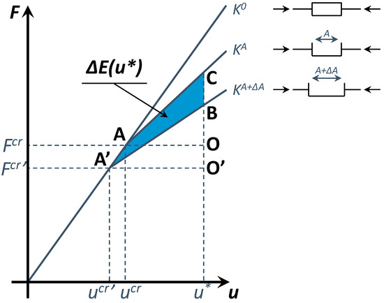
Figure 2.
Stiffened composite panel stiffness: K0: Before delamination buckling; KA: After the local delamination buckling; and KA+ΔA: After the propagated delamination buckling.
It can be assumed that the ERR distribution along the delamination front follows the same distribution of the square of the first buckling out-of-plane displacements:
where N is the number of the nodes belonging to the delamination front. Moreover, the location m, characterized by the maximum ERR, can be evaluated as:
Hence, the delamination will propagate from the location m, as soon as the local ERR Gm(u*) equates the critical value GIC.
One of the assumptions of the mode I Fast procedure is the predominance of mode I contribution on the total ERR. This assumption considerably reduces the field of applicability of the procedure to delamination very close to composite surface and characterized by very thin sub-laminates. Moreover, the instability of sub-laminates is mandatory for the application of the mode I based procedure. Hence, in order to extend the field of applicability of the fast procedure, in this paper, a Fast mode II based approach is introduced, which is aimed to improve the described Fast method by considering, in addition, the mode II contribution in the evaluation of the energy absorbed in the propagation phase of delamination. Indeed, in case of global buckling of the skin taking place far after the local buckling of the delaminated region (new assumption), the mode II contribution can be introduced into the evaluation of the released energy leading to the mixed modes (mode I and mode II) propagation. With this additional assumption, the global buckling phenomenon involves a displacement field, in the delaminated zone, compatible with fracture mode II which causes a mixed mode I and mode II delamination growth. Therefore, it is necessary to evaluate the global buckling relating it to local instability to evaluate the mode II contribution to delamination growth initiation. Assuming the critical global displacement of the skin uglo, two cases can be considered.
Case 1: Delamination growth initiation occurring before the global buckling (u* < uglo). This case is representative of mode I dominant propagation mode. Therefore, the theory developed for pure mode I is still effective, as shown in Figure 3. In addition, a coefficient α, which correlates the contribution of GIC and GIIC to the total ERR, is introduced, which ranges between zero (pure mode II) and one (pure mode I). Hence, the total amount of energy released during the propagation can be evaluated as:
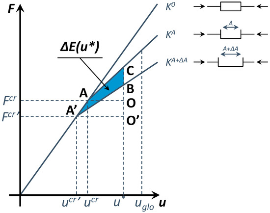
Figure 3.
Schematic rapresentation of energy relase rate evaluation considering mode I and mode II interaction: u* < uglo.
In this work, the coefficient α has been tuned by means of a non-linear VCCT analysis through Equation (5):
where GImax is the maximum value of GI found by non-linear VCCT analyses along the delamination front.
Indeed, with this approach an anticipation in delamination growth initiation is expected with respect to the pure mode I approach. This anticipation in growth initiation is due to the presence of the mode II contribution (neglected in the frame of pure mode I approach).
Case 2: Delamination growth initiation occurring after the global buckling (u* > uglo). In this case, the structure experiences the global buckling of the skin before delamination growth initiation takes place. Indeed, after the global buckling of the skin, the structure resulting stiffness can be assumed equal to the stiffness of the stringers, since the skin loses all the capabilities to further carry compressive load. Hence, the mode II released energy is related to both local and global critical load and the unknown propagation displacement u*. Therefore, according to Figure 4, the additional energy related to mode II can be evaluated as:
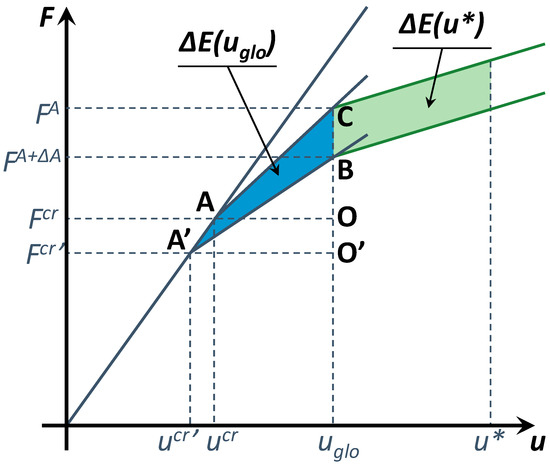
Figure 4.
Schematic rapresentation of energy relase rate evaluation considering mode I and mode II interaction: u* > uglo.
Once the global energy release rate has been related to the applied displacements, in order to determine the delamination growth initiation load, the maximum energy release rate along the delamination front should be equated to critical energy release rate in mixed mode configuration. Indeed, the GI and GII distributions along the delamination front can be assumed dependent on the local nodal out-of-plane and radial displacements, respectively:
where Δwi and Δri are, respectively, the opening and sliding displacements at location i of the delamination front.
Hence, the total amount of energy released during the propagation can be evaluated as:
where the location m, characterized by the maximum ERR, can be evaluated as:
3. Numerical Applications and Discussion
In this section, a preliminary validation of the proposed methodology is attempted. Comparisons against literature data on stiffened panels with circular delaminations have been used to prove the effectiveness of the proposed approach if compared to standard algorithms implemented in commercial finite element method (FEM) codes. The proposed fast delamination growth initiation procedure has been adopted here to investigate the damage behavior of stiffened CFRP panels subjected to compressive loads characterized by delaminations of different sizes and depths. Two test cases taken from literature [38,40] have been considered. The results obtained with the mode I Fast and mixed mode I and II Fast approaches have been compared each other and to standard non-linear VCCT results to verify the accuracy of the proposed methodology.
3.1. Test Case 1: Validation and Applicability of the Mode I Fast Procedure
The mode I Fast procedure has been implemented in the ABAQUS FEM code [41] by using a Python script interface. A refined FE model [42] has been introduced in the delamination region, to accurately evaluate the local buckling of the delaminated region. Indeed, a mesh sensitivity analysis has been performed to choose the optimum discretization for the finite element model. The structural configuration adopted for this first test-case [38] has been schematized in Figure 5. The mechanical properties of the adopted AS4/3501-6 material system are reported in Table 1. The stacking sequences of the skin, stringer cap, and stringer web are respectively [+45°/0°/90°/−45°]3s, [+45°/−45°/0°/0°/90°]s, and [+45°/−45°/0°/0°/90°]2s. A 20 mm radius delamination between the third and fourth ply (90°/−45° interface) has been considered.
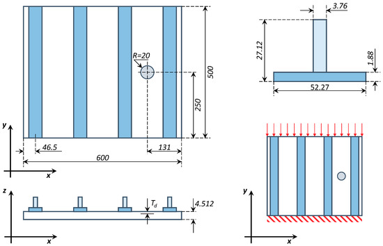
Figure 5.
Test case 1 geometrical description (dimensions in mm) and boundary conditions.

Table 1.
AS4/3501-6 material properties.
The FEM model has been discretized with eight-nodes SC8R layered elements. The stringer feet and the sub-laminates have been connected to the skin by means of TIE constraints, as shown in Figure 6. Indeed, a more refined mesh has been adopted in the local delamination region while a coarser discretization has been used for the rest of the panel. This choice allowed to obtain more accurate results while reducing the computational cost.

Figure 6.
Tie constraints: (a) skin-stringer bonding and (b) global-local interfaces.
As remarked in [38,39], a number of linear analyses on the configurations with delamination size A and A + ΔA are needed to evaluate the delamination growth initiation with the mode I fast procedure.
First, the delamination buckling displacement and load for the structure with delamination size A are obtained by means of a linearized buckling (Figure 7).

Figure 7.
Deformed shape of linear buckling analysis for the stiffened panel with delamination size A.
Then, the critical applied displacements ucr, the critical compressive load Fcr, and the linear nodal opening Δwi trend on the delamination front with a size A are evaluated. Hence, the node with maximum ERR is identified, as shown in Figure 8a.
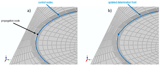
Figure 8.
Delamination front propagation node: (a) identification and (b) release.
A further linear buckling analysis is performed by releasing the node with maximum ERR on the delamination front, thus considering the delamination size A + ΔA shown in Figure 8b, to obtain the critical load and displacement Fcr’ and ucr’.
Then, the stiffness K0 of undamaged structure, the post-buckling stiffness KA of the structure with delamination size A, and the post-buckling stiffness KA+ΔA of the structure with delamination size A + ΔA are evaluated by means of static linear analyses. In order to evaluate the stiffness KA and KA+ΔA, the thinner sub-laminate has been removed from the finite element model to take in account the stiffness lost related to the delamination buckling. Finally, the applied loads and displacements at growth initiation and the ERR on the delamination front are evaluated.
Several analyses have been carried out by considering different mesh densities along the tangential and radial directions of the local delamination region, in order to assess the mesh-dependency for the proposed approach. In particular, different mesh densities have been considered in a circular area around the delamination front, where the nodal displacements are evaluated. Therefore, the number of elements in the radial direction has been progressively increased. In Figure 9, the configurations characterized by two, four, and eight elements are shown, and the influence of the mesh densities on the critical propagation strain is reported as well.
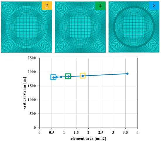
Figure 9.
Influence of the element discretization in the radial direction on the critical propagation strain.
Moreover, the influence of the mesh discretization in the tangential direction on the critical propagation strain has been assessed in Figure 10. Indeed, the number of elements in the radial direction has been progressively increased, as shown in Figure 10 for the configurations characterized by 56, 80, and 96 elements.
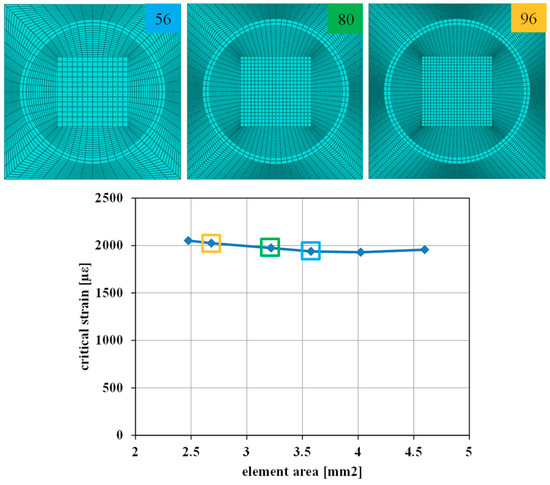
Figure 10.
Influence of the element discretization in the tangential direction on the critical propagation strain.
According to Figure 9 and Figure 10, the discretization of the elements in the delaminated region has a negligible influence on the critical propagation strain.
Finally, the effectiveness of the mode I Fast approach has been demonstrated in Figure 11, where the ERRs predicted by both the standard VCCT and the proposed methods on the delamination front at growth initiation have been compared. Good agreements on the compressive buckling strains εbuckling and the compressive delamination initiation strains εdel and loads Fdel between the proposed linear approach and VCCT can be found as well, as reported in Table 2. Moreover, the advantage of the Fast procedure in terms of computational efforts, respect to the standard VCCT approach, can be appreciated by comparing the computational times reported in Table 2.
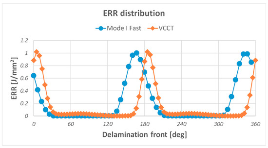
Figure 11.
Comparison of proposed approach and virtual crack closure technique (VCCT) in terms of normalized energy release rate (ERR) distribution along delamination front.

Table 2.
Critical propagation loads and computational time comparison.
The mode I Fast procedure is based on the hypothesis that the delamination mainly propagates due to the effect of the fracture mode I. However, this hypothesis limits the field of applicability of the approach to very thin panels with very superficial delaminations. Hence, an investigation of the influence of the delaminated sub-laminate relative thickness on the delamination growth initiation load has been performed and compared to VCCT results. Figure 12 reports the error, with respect to the VCCT approach, on the delamination growth initiation load as a function of the delamination depth.
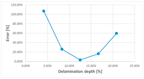
Figure 12.
Application limits of linear procedure.
According to Figure 12, a limited range of applicability between 10–20% of delamination depth is observed for the mode I Fast approach. Indeed, very thin delaminations lead to a significant delay in delamination growth with respect to the local delamination buckling. This delay involves significant geometrical non-linear effects in contrast with the main hypothesis of linear structural behavior for the applicability of the mode I fast procedure. Moreover, very thick delaminations, involving mixed mode I and mode II growth, do not satisfy the main assumption on the predominance of mode I for the applicability of mode I fast procedure.
In order to increase this limited range of applicability and to obtain more accurate results, a modified version of the mode I fast procedure has been investigated which considers the influence of fracture mode II in the evaluation of energy released during the propagation.
3.2. Test Case 2: Validation and Applicability of the Mixed Mode I and II Fast Procedure
The mixed mode I and II Fast procedure has been also implemented in the ABAQUS FEM code [41] by using a Python script interface. The effectiveness of this enhanced version of the fast procedure compared to the mode I fast procedure has been tested on CFRP stiffened panels with a circular delamination with variable size and depth. The structural configuration [40] adopted for this second test-case has been schematized in Figure 13. The mechanical properties of the adopted (T800/924) material system are reported in Table 3. The stacking sequences of the skin and each of the stringers are respectively [(+45°/−45°/0°/90°)4]S and [(−45°/+45°/0°)2]S2.
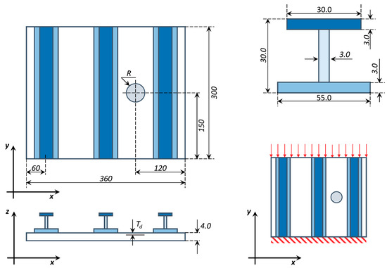
Figure 13.
Test case 2 geometrical description (dimensions in mm) and boundary conditions.

Table 3.
T800/924 material properties.
In particular, two configurations, named SS#1 and SS#4, have been analyzed, characterized by bay circular delaminations with a radius of 25 mm and 17.5 mm, respectively. For each configuration, different delamination depths have been considered, and the influence of the size and depth of the delamination on the delamination growth initiation is assessed. The VCCT method has been adopted to prove the effectiveness of the proposed mixed mode I and II fast procedure in terms of critical load and ERR distribution along the delamination front.
In Figure 14, the global model and the local thicker and thinner sub-laminates are shown. Indeed, the delamination depth is compatible with low velocity impact induced damages.
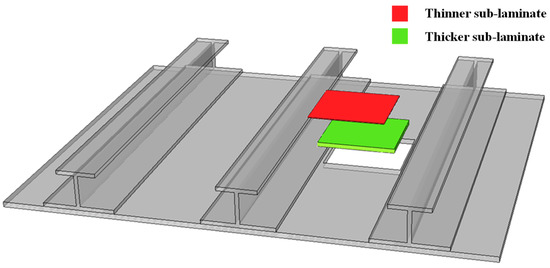
Figure 14.
Details of global-local approach adopted in FE simulation.
For both configurations, different delamination depths have been considered to assess the effectiveness and the limits of applicability of proposed mixed mode I and II fast procedure with respect to the standard mode I fast procedure. In Table 4 and Table 5, the delamination growth initiation applied strains obtained by the standard VCCT approach, by the mode I Fast approach, and by the mixed mode I and II Fast approach for different delamination depths have been reported for the SS#1 and SS#4 configurations, respectively. Moreover, the delamination growth initiation applied strain deviations of both mode I Fast and mixed mode I and II Fast approaches with respect to the VCCT method have been reported as well.

Table 4.
Results summary for SS#1 damage configuration (25 mm radius delamination).

Table 5.
Results summary for SS#4 damage configuration (17.5 mm radius delamination).
Figure 15 and Figure 16 compare the results of the mode I Fast and mixed mode I and II Fast approaches, in terms of delamination growth initiation load deviation from the VCCT results, of the SS#1 and SS#4 configurations, respectively. Indeed, the mixed mode I and II Fast procedure allows the extension of the range of applicability of the mode I Fast procedure, reducing the error in term of delamination growth initiation load evaluation.
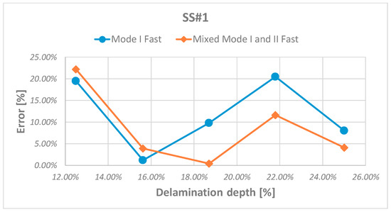
Figure 15.
Error of critical load evaluation versus depth for SS#1 damage configuration.
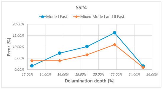
Figure 16.
Error of critical load evaluation versus depth for SS#4 damage configuration.
Then, the strain energy release rate (SERR) distributions for the analyzed configurations have been investigated in order to assess the effectiveness of the mixed mode I and II Fast procedure in predicting the actual growth location along the delamination front. Again, the effectiveness of the mixed mode I and II Fast approach can be appreciated by comparing the results, in terms of mode I and mode II SERR distributions, to the VCCT ones. In particular, in Figure 17 and Figure 18, the comparisons between SERR considering a delamination between the fifth and sixth ply (+45°/−45° interface), for SS#1 and SS#4 configurations respectively, are shown.
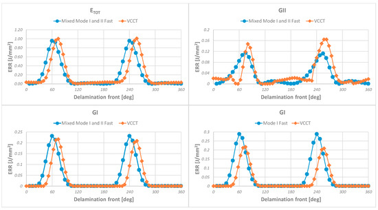
Figure 17.
Comparison of strain energy release rate (SERR) distribution for SS#1 damage configuration.
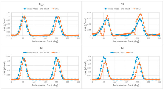
Figure 18.
Comparison of SERR distribution for SS#4 damage configuration.
In both cases (of Figure 17 and Figure 18), the implemented mixed mode I and II Fast approach provides good results, showing an excellent agreement with SERR distribution predicted with the non-linear technique. The distribution of mode II SERR is related to the radial component of the displacement field on the delamination front. Hence, it is strongly influenced by depth of delamination and ply interface. Indeed, nonlinear analysis performed on SS#1 damage configuration with six plies for delaminated sub-laminate, at −45°/0° interface, shows (Figure 19) that radial component distribution on delamination front is far from GII distribution probably because the strain energy release rate distribution undergoes significant variations from the delamination buckling condition to delamination growth condition, eventually, passing through the global buckling of the skin.
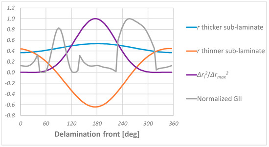
Figure 19.
Radial displacement field from non-linear analysis.
Figure 20 shows the predicted SERR distribution compared to VCCT. As expected, the radial displacement for the SS#1 damage configuration is not suitable for the evaluation of the GII distribution.

Figure 20.
SS#1-comparison between mixed mode I and II fast procedure and VCCT of SERR distribution.
4. Conclusions
In this work, the delamination growth initiation in stiffened composite panels subjected to compressive load has been investigated. A modified version of a previously developed mode I Fast procedure, based on linear analyses, has been proposed here for the study of circular delamination growth initiation under mixed mode I and mode II propagation. The approach has been preliminary validated for embedded delaminations in composite stiffened panels. Several stiffened panel configurations, taken from literature, with embedded bay skin delaminations characterized by different sizes and depths have been analyzed.
The proposed mixed mode I and mode II Fast approach has been used to investigate the influence of the size and depth of the delamination on the damage tolerance of stiffened CFRP panels, comparing the results with standard numerical non-linear technique. The results have demonstrated that the delamination size and depth strongly influence the delamination growth leading to a change in the propagation mode. Indeed, the mixed mode I and mode II Fast procedure has been found able to extend the field of applicability of the previously developed mode I Fast procedure by including also configurations characterized by a not negligible mode II contribution to the delamination growth.
Different element sizes, considering mesh density variations along the radial and tangential direction, in the area around the delamination front have been used in order to prove the robustness and mesh independency of implemented method.
The results of the proposed fast approach have been found in excellent agreement with standard numerical non-linear technique data in term of delamination growth initiation load prediction and strain energy release rate distribution along the delamination front, allowing up to 95% computational cost saving with respect to the standard non-linear VCCT approach. However, the proposed novel procedure fails to predict the strain energy release rate for geometrical configuration with very thick delaminations where the strain energy rate distribution strongly changes from delamination buckling to delamination growth stages.
Author Contributions
All authors equally contributed to this work.
Funding
This research received no external funding.
Conflicts of Interest
The authors declare no conflict of interest.
References
- Seon, G.; Makeev, A.; Nikishkov, Y.; Lee, E. Effects of defects on interlaminar tensile fatigue behavior of carbon/epoxy composites. Compos. Sci. Technol. 2013, 89, 194–201. [Google Scholar] [CrossRef]
- Andrews, S.D.; Ochoa, O.O.; Owens, S.D. The Effects of Fastener Hole Defects. J. Compos. Mater. 1993, 27, 2–20. [Google Scholar] [CrossRef]
- Elder, D.J.; Thomson, R.S.; Nguyen, M.Q.; Scott, M.L. Review of delamination predictive methods for low speed impact of composite laminates. Compos. Struct. 2004, 66, 677–683. [Google Scholar] [CrossRef]
- Geubelle, P.H.; Baylor, J.S. Impact-induced delamination of composites: A 2D simulation. Compos. Part B Eng. 1998, 29, 589–602. [Google Scholar] [CrossRef]
- Parlapalli, M.R.; Soh, K.C.; Shu, D.W.; Ma, G. Experimental investigation of delamination buckling of stitched composite laminates. Compos. Part A Appl. Sci. Manuf. 2007, 38, 2024–2033. [Google Scholar] [CrossRef]
- Craven, R.; Iannucci, L.; Olsson, R. Delamination buckling: A finite element study with realistic delamination shapes, multiple delaminations and fibre fracture cracks. Compos. Part A Appl. Sci. Manuf. 2010, 41, 684–692. [Google Scholar] [CrossRef]
- Karihaloo, B.L.; Stang, H. Buckling-driven delamination growth in composite laminates: Guidelines for assessing the threat posed by interlaminar matrix delamination. Compos. Part B Eng. 2008, 39, 386–395. [Google Scholar] [CrossRef]
- Ashizawa, M. Fast Interlaminar Fracture of a Compressively Loaded Composite Containing a Defect. In Proceedings of the Fifth DOD/NASA Conference on Fibrous Composites in Structural Design; Report No. NADC-81096-60; Naval Air Development Center: Warminster, PA, USA, January 1981; pp. 1–1269. [Google Scholar]
- Ramkumar, R.L. Fatigue Degradation in Compressively Loaded Composite Laminates; NASA CR-165681; NASA Langley Research Center: Hampton, VA, USA, 1981.
- Ramkumar, R.L. Performance of a Quantitative Study of Instability-Related Delamination Growth; NASA CR-166046; NASA Langley Research Center: Hampton, VA, USA, 1983.
- Byers, B.A. Behaviour of Damaged Graphite/Epoxy Laminates under Compression Loading; NASA CR-159293; NASA Langley Research Center: Hampton, VA, USA, 1980.
- Chai, H.; Knauss, W.G.; Babcock, C.D. Observation of Damage Growth in Compressively Loaded Laminates. Exp. Mech. 1983, 23, 329–337. [Google Scholar] [CrossRef]
- Shivakumar, K.N.; Whitcomb, J.D. Buckling of a Sublaminate in a Quasi-Isotropic Composite Laminate. J. Compos. Mater. 1985, 19, 2–18. [Google Scholar] [CrossRef]
- Whitcomb, J.D.; Shivakumar, K.N. Strain-Energy Release Rate Analysis of a Laminate with a Postbuckled delamination. In Numerical Methods in Fracture Mechanics; NASA TM-89091; NASA Langley Research Center: Hampton, VA, USA, 1987. [Google Scholar]
- Kim, H.J.; Hong, C.S. Buckling and Postbuckling Behaviour of Composite Laminates with an Embedded Delamination. Compos. Sci. Technol. 1997, 57, 557–564. [Google Scholar] [CrossRef]
- Singh, K.L.; Dattaguru, B.; Ramamurthy, T.S.; Mangalgiri, P.D. Delamination Tolerance Studies in Laminated Composite Panels. Sadhana 2000, 25, 409–422. [Google Scholar] [CrossRef]
- Shahwan, K.; Waas, A.M. Unilateral Buckling of rectangular Plates. Int. J. Solids Struct. 1994, 31, 75–89. [Google Scholar] [CrossRef]
- Shahwan, K.; Waas, A.M. Buckling of Unilaterally Constrained Plates: Application to the Study of Delaminations in Layered Structures. J. Frankl. Inst. 1998, 335, 1009–1039. [Google Scholar] [CrossRef]
- Whitcomb, J.D. Analysis of a Laminate with a Postbuckled Embedded Delamination, Including Contact Effects. J. Compos. Mater. 1992, 26, 1523–1535. [Google Scholar] [CrossRef]
- Whitcomb, J.D. Three Dimensional Analysis of a Postbuckled Embedded Delamination. J. Compos. Mater. 1989, 23, 862–889. [Google Scholar] [CrossRef]
- Köllner, A.; Völlmecke, C. Post-buckling behaviour and delamination growth characteristics of delaminated composite plates. Compos. Struct. 2018, 203, 777–788. [Google Scholar] [CrossRef]
- Kutlu, Z.; Chang, F.-K. Modeling Compression Failure of laminated Composites Containing Multiple Through-the-Width Delaminations. J. Compos. Mater. 1992, 26, 350–387. [Google Scholar] [CrossRef]
- Orifici, A.C.; de Zarate Alberdi, I.O.; Thomson, R.S.; Bayandor, J. Compression and post-buckling damage growth and collapse analysis of flat composite stiffened panels. Compos. Sci. Technol. 2008, 68, 3150–3160. [Google Scholar] [CrossRef]
- Krueger, R. The Virtual Crack Closure Technique: History, Approach and Applications; NASA/CR-2002-211628; ICASE Report; NASA Langley Research Center: Hampton, VA, USA, 2002.
- Liu, P.F.; Hou, S.J.; Chu, J.K.; Hu, X.Y.; Zhou, C.L.; Liu, Y.L.; Zheng, J.Y.; Zhao, A.; Yan, L. Finite element analysis of postbuckling and delamination of composite laminates using virtual crack closure technique. Compos. Struct. 2011, 93, 1549–1560. [Google Scholar] [CrossRef]
- Gudmundson, P. Micromechanically based constitutive models for damage evolution in composite laminates. Int. J. Damage Mech. 2000, 9, 29–39. [Google Scholar] [CrossRef]
- Turon, A.; Dávila, C.G.; Camanho, P.P.; Costa, J. An engineering solution for mesh size effects in the simulation of delamination using cohesive zone models. Eng. Fract. Mech. 2007, 74, 1665–1682. [Google Scholar] [CrossRef]
- Riccio, A.; Linde, P.; Raimondo, A.; Buompane, A.; Sellitto, A. On the use of selective stitching in stiffened composite panels to prevent skin-stringer debonding. Compos. Part B Eng. 2017, 124, 64–75. [Google Scholar] [CrossRef]
- Riccio, A.; Russo, A.; Sellitto, A.; Raimondo, A. Development and application of a numerical procedure for the simulation of the “Fibre Bridging” phenomenon in composite structures. Compos. Struct. 2017, 168, 104–119. [Google Scholar] [CrossRef]
- Hallett, S.R.; Green, B.G.; Jiang, W.G.; Wisnom, M.R. An experimental and numerical investigation into the damage mechanisms in notched composites. Compos. Part A Appl. Sci. Manuf. 2009, 40, 613–624. [Google Scholar] [CrossRef]
- Hughes, T.; Cottrell, J.; Bazilevs, Y. Isogeometric analysis: CAD, finite elements, NURBS, exact geometry and mesh refinement. Comput. Methods Appl. Mech. Eng. 2005, 194, 4135–4195. [Google Scholar] [CrossRef]
- Dimitri, R.; Fantuzzi, N.; Tornabene, F.; Zavarise, G. Innovative numerical methods based on SFEM and IGA for computing stress concentrations in plates with discontinuities. Int. J. Mech. Sci. 2016, 118, 166–187. [Google Scholar] [CrossRef]
- Nguyen, V.P.; Nguyen-Xuan, H. High-order B-splines based finite elements for delamination analysis of laminated composites. Compos. Struct. 2013, 102, 261–275. [Google Scholar] [CrossRef]
- Guo, Y.; Nagy, A.P.; Gürdal, Z. A layerwise theory for laminated composites in the framework of isogeometric analysis. Compos. Struct. 2014, 107, 447–457. [Google Scholar] [CrossRef]
- Dimitri, R.; Zavarise, G. Isogeometric treatment of frictional contact and mixed mode debonding problems. Comput. Mech. 2017, 60, 315–332. [Google Scholar] [CrossRef]
- Dimitri, R.; Tornabene, F. Numerical Study of the Mixed-Mode Delamination of Composite Specimens. J. Compos. Sci. 2018, 2, 30. [Google Scholar] [CrossRef]
- Dimitri, R.; Tornabene, F.; Zavarise, G. Analytical and numerical modeling of the mixed-mode delamination process for composite moment-loaded double cantilever beams. Compos. Struct. 2018, 187, 535–553. [Google Scholar] [CrossRef]
- Riccio, A.; Damiano, M. A Fast Numerical Methodology for Delamination Growth Initiation Simulation. In Damage Growth in Aerospace Composites; Springer: Berlin/Heidelberg, Germany, 2015; pp. 199–220. ISBN 978-3-319-04003-5. [Google Scholar]
- Riccio, A.; Damiano, M.; Raimondo, A.; Di Felice, G.; Sellitto, A. A fast numerical procedure for the simulation of inter-laminar damage growth in stiffened composite panels. Compos. Struct. 2016, 145, 203–216. [Google Scholar] [CrossRef]
- Riccio, A.; Zarrelli, M.; Giordano, M. A Linear Numerical Approach to Simulate the Delamination Growth Initiation in Stiffened Composite Panels. J. Compos. Mater. 2010, 44, 1841–1866. [Google Scholar] [CrossRef]
- ABAQUS Manual; Revision 6.5-1; Theory; Dassault Systèmes Simulia Corp.: Providence, RI, USA, 2004.
- Sellitto, A.; Borrelli, R.; Caputo, F.; Riccio, A.; Scaramuzzino, F. Methodological approaches for kinematic coupling of non-matching finite element meshes. Procedia Eng. 2011, 10, 421–426. [Google Scholar] [CrossRef][Green Version]
© 2019 by the authors. Licensee MDPI, Basel, Switzerland. This article is an open access article distributed under the terms and conditions of the Creative Commons Attribution (CC BY) license (http://creativecommons.org/licenses/by/4.0/).