Article

Research on Dynamic Modeling and Transition Flight Strategy of VTOL UAV

College of Aeronautics, Northwestern Polytechnical University, Xi’an 710072, China
*
Author to whom correspondence should be addressed.
Appl. Sci. 2019, 9(22), 4937; https://doi.org/10.3390/app9224937
Submission received: 8 October 2019 / Revised: 13 November 2019 / Accepted: 15 November 2019 / Published: 16 November 2019

Abstract

:

Featured Application

The new vertical take-off and landing UAV meets the requirements of vertical take-off and landing and can cruise at high speed, which lays a good foundation for future military and civil fields.

Abstract

A vertical take-off and landing (VTOL) unmanned aerial vehicle (UAV) can meet both VTOL and horizontal flight performance, but how to achieve a safe and stable transition is a research focus of this type of aircraft. According to the overall configuration characteristics of VTOL UAV, aerodynamic models of lift fan, lift duct and induced wing surface of VTOL UAV were established. Three flight modes of induced VTOL UAV are studied, including hover, transition and horizontal flight. The method of longitudinal flight balance of UAV in transition mode is also studied. Finally, a UAV is taken as an example to conduct the research of transition flight mode balancing and flight simulation with the method presented in this paper. The results show that the proposed method can reasonably give the control quantity and longitudinal attitude of UAV in the whole transition mode, so that the UAV can achieve a steady transition flight.

1. Introduction

1.1. Background

The induced VTOL UAV is a new type of UAV. It combines performances of both helicopter and fixed-wing aircraft, such as vertical take-off/landing, air hovering and low altitude and low speed of helicopter, and high-altitude cruise of fixed-wing aircraft. With excellent performance and good economy, it plays an important role in both military and civil fields and has broad development prospects.

1.2. Formulation of the Problem

There are three main flight modes of the UAV: take-off/landing mode, horizontal flight mode and transition flight mode. During the transition, the aircraft configuration changes constantly, and various control units work together to meet the requirements of smooth flight. In this process, the reasonable distribution of power and the reasonable range of speed must be considered, so as to ensure that the lift force of the UAV meets the flight requirements, and the flight attitude in the process is continuously changing. Therefore, transition flight mode is the most complex flight mode of VTOL UAV. In order to ensure the safety of transition flight, it is necessary to determine the transition flight corridor of the aircraft so that the aircraft can safely transition in the transition flight corridor. In addition, the establishment of the dynamic mathematical model of the variable configuration aircraft, and how to accurately describe its transition flight motion, are also the focus of the study [1,2,3].

1.3. Literature Survey

Due to the special configuration of the induced lift aircraft, there are few studies in this aspect. There are many studies on vertical take-off/landing, including aerodynamic characteristics calculation, dynamic modeling, and flight performance. J. Geordon Leishman and Shreyas Ananthan [4,5] studied the theoretical calculation model of the coaxial dual rotor paired lift fan, established the aerodynamic calculation model of the coaxial dual rotor based on the blade element momentum theory, and studied the optimal blade matching of the upper and lower rotors of the coaxial dual rotor through the theoretical model. B.Yuksek and A.Vuruskan [6] established a six-degree-of-freedom nonlinear equation for lift-fan-type vertical take-off and landing UAV and carried out simulation based on the established mathematical model. Taking tilt-rotor aircraft as the research object, Shi Xiaoming [7] modeled the longitudinal aircraft and established the aerodynamic model of the aerodynamic components of the aircraft and carried out the balancing and stability analysis of the transition stage according to the established longitudinal model. Taking tilt-rotor aircraft as the object, Cao Yunyun [8] studied the determination method of tilt-rotor corridor envelope, established a dynamic model, and analyzed and calculated the case according to the model. According to the characteristics of the aircraft, the control strategy of tilting rotor is studied to meet the requirements of hover, low speed flight and transition flight mode. Wan Huafang [9] established the dynamic theory model of tilt-rotor aircraft and conducted simulation research on the transition corridor. These works focused on the dynamics modeling and transition corridor research of tilt-rotor aircraft and lift fan aircraft. Thus, the dynamic modeling and transition corridor of the UAVs will be investigated. Zhang Juqiang [10] proposed an adaptive fuzzy-based global sliding mode control strategy for quadrotor UAVs in robust trajectory tracking against parameter uncertainties and external disturbances. Sepehr P. Khaligh [11] provided an inverse kinematic solution for the main rotor actuating mechanism of a small-scale helicopter that includes a four-point swashplate system and a Bell–Hiller mixer and the tail rotor actuating mechanism are derived using an approach that is suitable for real-time control applications.

1.4. Scope and Contribution of This Study

In this paper, aiming at the problem of longitudinal flight state and transition flight balance of the induced lift aircraft, a parameterized aerodynamic model suitable for longitudinal flight of the induced lift aircraft is firstly established, including the aerodynamic model of the whole machine, the aerodynamic model of the lift fan and the aerodynamic model of the booster device which uses the blade-element moment theory (BEMT). On the basis of this model, a mathematical model of UAV longitudinal motion is established by using a six degrees of freedom method, and the flight strategy of induced lift vehicle in longitudinal flight is studied to meet the requirements of vertical take-off, transition and horizontal flight. Finally, a certain type of UAV is taken as an example to balance various flight modes. The method is applied to the case, then the flight simulation is carried out, and the feasible flight strategy of transition flight is obtained.

1.5. Organization of the Paper

The rest of this paper is organized as follows. In the Section 2, the aerodynamic models of lift fan, lift duct, induced wing surface and wing are established. In the Section 3, the dynamic model of the lift fan, the dynamic model of the lift duct and the mathematical model of the longitudinal motion of the whole machine are established. In the Section 4, balancing calculation is carried out for the hover and transition states of VTOL UAV. In the Section 5, a certain type of UAV is taken as an example to obtain the stable transition flight strategy. The discussion and conclusion are given in Section 6 and Section 7, respectively.

2. Aerodynamic Expression

The main aerodynamic components of the UAVs include the contra lift fan, the left and right lift ducts, the left and right induced wing surfaces and the main wing. In this paper, the aerodynamic modeling of the whole machine adopts the body coordinate system. The origin of the axis is located at the center of gravity position of the UAV. The X-axis points in front of the nose along the symmetrical plane of the aircraft structure, and Y-axis is perpendicular to the X-axis to the right of the body, and the Z-axis is determined downward by the right-hand rule, as shown in Figure 1. The model of aerodynamic parts is based on the body coordinate system of aerodynamic parts.

2.1. Aerodynamic Model of Lift Fan

Compared with the isolated propeller, the ducted propeller produces larger tension at the same power and the same diameter, that is, the diameter required to produce the same tension at the same power is smaller. The mechanism of ducted propeller causing this difference is as follows:
  • The presence of duct changes the slipstream state of the propeller downstream, such as increasing the slipstream area, and reducing the slipstream velocity and slipstream energy loss, so that more kinetic energy behind the propeller disc was converted into pressure energy.
  • The duct wall improves the turbulence characteristics of the propeller tip and reduces the flow loss around it.
  • A large zone with low pressure is formed at the leading edge of the inlet of the duct, generating additional tension.
The coaxial contra rotating lift fans are a pair of lift fans installed in tandem and rotating around the same axis with opposite direction. The coaxial contra-rotating lift fan has the following advantages:
  • Due to coaxial rotation, the reaction torque from the engine to the aircraft is reduced to zero.
  • Under the condition of Vmax, the total efficiency of coaxial propeller is higher than that of non-coaxial propeller with the same number of blades with the same flight conditions (V0, H, n, N and D).
  • In high-speed flight, the efficiency of coaxial propeller is higher than that of the two isolated propellers with the same task.
  • The take-off performance (in-situ tension) of a coaxial propeller is better than that of a single propeller.
At present, there is no coaxial dual-rotor aerodynamic theory with duct for reference. Based on the mathematical model of coaxial dual-rotors, the method of duct tension factor q is introduced to give the dynamic model of coaxial dual-rotor ducted fan.
The Blade Element Moment Theory (BEMT) [12,13] is used to calculate the lift, power and moment of the coaxial double-rotor. The dimensionless form proposed by NASA [14] is adopted to calculate the formula:
T = ρ A ( Ω R ) 2 C T P = ρ A ( Ω R ) 3 C P M = ρ A R ( Ω R ) 2 C M ,
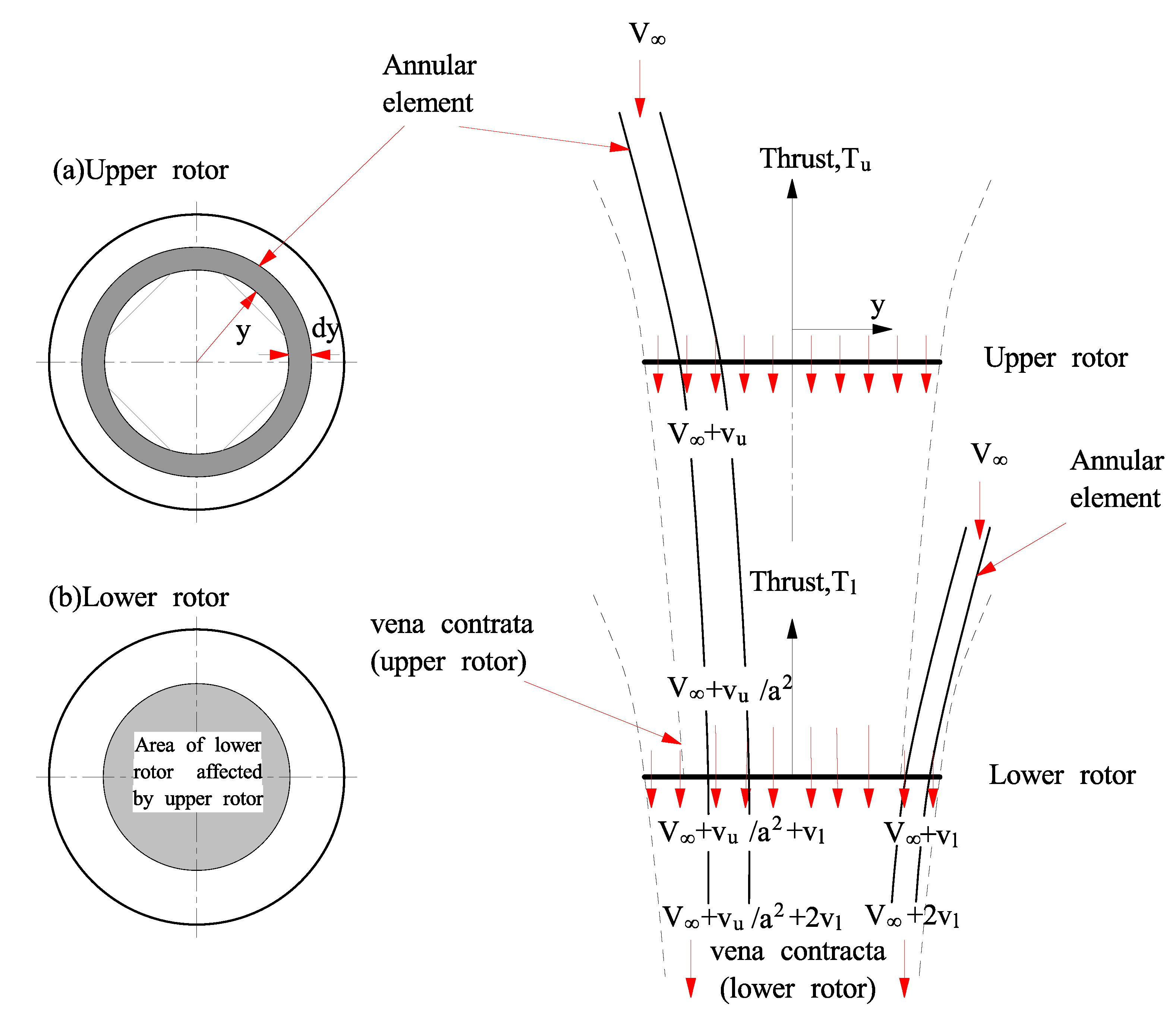
The flow model of the coaxial dual rotor system is shown in the Figure 2. The basic assumption is that the area of the propeller disk of the lower rotor works in the wake area of the upper rotor, and the slipstream velocity of the upper rotor has a maximum change in the vena contracta before the wake of the upper rotor enters the rotor disk. The contraction of the wake is based on the ideal fluid flow hypothesis or supported by specific experimental data [4,5,15,16,17].
The BEMT model assumes that the slipstream (outflow) of the upper rotor affects the slipstream (inflow) of the lower rotor, while the lower rotor does not affect inflow of the upper rotor. The theory of blade element momentum can be generalized with the axial free inflow velocity, which is generally denoted as V . For the upper rotor of the coaxial system, momentum theory principles can be used to find incremental thrust from the mass flow rate through the annulus and the induced velocity there. Mass flow velocity through rotor annulus is expressed as:
d m ˙ = ρ ( V + v u ) d A = 2 π ρ ( V + v u ) y d y ,
where d A = 2 π y d y , so the increase in thrust over the annular area is as follows:
d T u = 2 ρ ( V + v u ) v u d A = 4 π ρ ( V + v u ) v u y d y .
To convert the thrust into a compiled form, the above equation can be written as
d C T u = d T u ρ ( π R 2 ) ( Ω R ) 2 = 2 ρ ( V + v u ) v u d A ρ π R 2 ( Ω R ) 2 = 2 ρ ( V + v u ) v u ( 2 π y d y ) ρ π R 2 ( Ω R ) 2 = 4 λ λ u r d r ,
where λ = v / Ω R , λ u = v u / Ω R , λ = V / Ω R , v = V + v u ; and r = y / R stands for dimensionless radial position. Therefore, the tension coefficient of the annular area can be written as
d C T u = 4 λ λ u r d r = 4 λ ( λ λ ) r d r ,
Similarly, the power coefficient of the annular area can be expressed as
d C P u = λ d C T u = 4 λ 2 λ u r d r = 4 λ 2 ( λ λ ) r d r .
The tip loss in BEMT can be calculated by means of Prandtl tip-loss equation, and the expression of the correction factor F of tip loss is as follows [18]
F = ( 2 / π ) cos 1 ( exp ( f ) ) ,
where f is given through the number of blades N b and the radial position r of the blade element, and the expression is as follows
f = N b 2 ( 1 r r ϕ ) ,
where ϕ = λ ( r ) / r is the inflow angle under the assumption of small angle. Then the tension coefficient of the annular area modified by Prandtl propeller tip loss equation is expressed as
d C T = 4 F λ λ u r d r .
According to the classical blade element theory, the tension generated by the same annular area on the paddle disc is expressed as
d C T u = 1 2 σ u C l r 2 d r = 1 2 σ u C l α ( θ u ϕ ) r 2 d r = σ u C l α 2 ( θ u r 2 λ r ) d r ,
where, θ u refers to the blade pitch of the upper rotor, which may include the zero lift angle of attack of the blade section, and σ u is the degree of disc consolidation. By comparing the tension coefficients obtained by the classical blade element theory and the blade element momentum theory, it can be obtained to be
σ u C l α 2 ( θ u r 2 λ r ) = 4 F λ ( λ λ ) r ,
Convert this into a quadratic equation of λ
λ 2 + ( σ u C l α 8 F λ ) λ σ u C l α 8 F θ u r = 0 ,
This equation has the solution
λ ( r , λ ) = ( σ u C l α 16 F λ 2 ) 2 + σ u C l α 8 F θ u r ( σ u C l α 16 F λ 2 ) ,
where λ u = λ λ . The above equation can be solved numerically on a series of discrete elements of the paddle disk.
The same mathematical principle can be applied to the analysis of the lower rotor as well. According to the previous hypothesis, a part of the lower rotor works in the slipstream area of the upper rotor. In an ideal state, the vena contracta can be obtained according to the contraction of the flow tube A c = π a 2 R 2 , where a = 0.707 , A c / A = 0.5 . In this particular case, the inner area of the lower rotor encounters incoming contracted differential streamtubes with velocity V + v u / a 2 .
With the same calculation method as that of the upper rotor, the velocity of the lower rotor in the area ( r a ) affected by the slipstream of the upper rotor can be obtained
λ ( r , λ ) = ( σ l C l α 16 F λ + λ u / a 2 2 ) 2 + σ l C l α 8 F θ l r ( σ u C l α 16 F λ + λ u / a 2 2 ) ,
where θ l refers to the blade pitch of the lower rotor, λ l = λ λ .
For the area ( r > a ) that is not affected by the slipstream of the upper rotor, the velocity is calculated as follows
λ ( r , λ ) = ( σ l C l α 16 F λ 2 ) 2 + σ l C l α 8 F θ l r ( σ l C l α 16 F λ 2 ) ,
The above three equations give the approximate calculation method of velocity of each discrete radial position of upper and lower rotor at any blade pitch, blade torsion and airfoil section.
According to the above calculation formula of tension coefficient and flow velocity, the tension, power and torque of the rotor can be obtained by numerical integration of each rotor disc. The tension coefficient of the upper rotor is expressed as follows
C T u = r = 0 r = 1 d C T u = 1 2 0 1 σ u C l r 2 d r ,
The power coefficient is expressed as follows
C P u = r = 0 r = 1 λ u d C T u + 0 1 1 2 σ u C d r 3 d r ,
where C d is the sectional profile drag coefficient. In approximate calculation, C d can be replaced by the zero-rise resistance coefficient C d 0 . In general, for a specific airfoil blade, the drag coefficient needs to be obtained by looking up the table.
According to the relationship between the dimensionless power coefficient and the torque coefficient, the expression of the torque coefficient can be obtained as follows
C M u = C P u / 2 π ,
For the upper rotor, the tension coefficient, power coefficient and torque coefficient are as follows
C T l = r = 0 r = 1 d C T l = 1 2 0 1 σ l C l r 2 d r ,
C P l = r = 0 r = 1 λ l d C T l + 0 1 1 2 σ l C d r 3 d r ,
C M l = C P l / 2 π ,
respectively, where it should be noted that σ u σ l , in general. The double-rotor can adjust the blade pitch, speed and other parameters to meet the tension demand. Under normal working conditions, the torque of the upper and lower rotor is balanced, that is C M u = C M l .
Then the tension coefficient, power coefficient and torque coefficient of the coaxial double-rotor propeller are expressed as follows
C T p = C T u + C T l ,
C P p = C P u + C P l ,
C M p = C M u + C M l .
At present, there is no ducted coaxial dual-rotor aerodynamics theory for reference. In this paper, the aerodynamics model of ducted coaxial dual-rotor was derived by referring to the above BEMT method, and the factor q of duct tension ratio is introduced to establish the aerodynamics model of ducted coaxial dual-rotor. The total tension of ducted fan is
T f = T s + T p = q T f + T p ,
q = T s T f ,
There is no theoretical formula for duct tension factor q [19]. At the present stage, the approximate curve of the ratio of propeller tension to total tension T is given based on the research results of R. kiriebel [20] on thin cylindrical ducted propeller, as is shown in the Figure 3
T p T f = 1 1 + f 1 ,
q = T s T f = f 1 1 + f 1 ,
The fitting formula of tension factor q curve is (take x ¯ = L / D , where L is the duct length, and D is the duct diameter).
  • When 0 < x ¯ < 0.2 , f 1 = 100 x ¯ 3 52.8571 x ¯ 2 + 10.3214 x ¯ + 0.0007143 ;
  • When 0.2 < x ¯ < 1 , f 1 = 0.8544 x ¯ 3 1.9389 x ¯ 2 + 1.4973 x ¯ + 0.5252 .
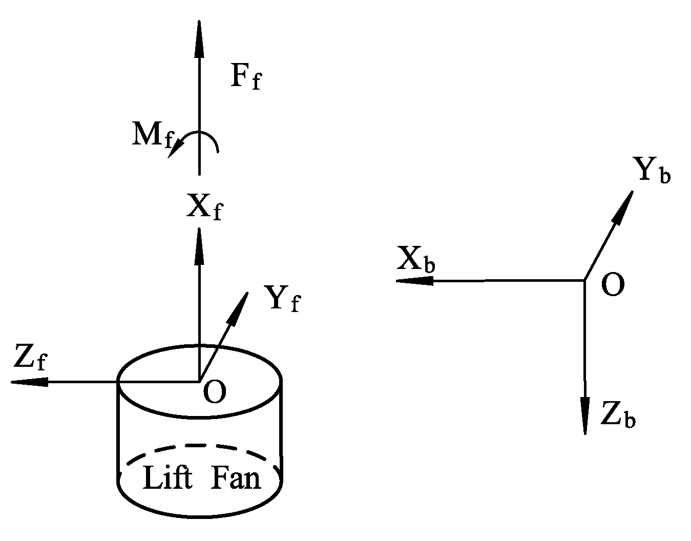
The aerodynamic force and torque of the lift fan system are transferred to the Body coordinate system. The force and torque are shown in the Figure 4.
The coordinate transformation matrix of a lift fan coordinate system and body coordinate system is R b f , and its dimension is 3 × 1. Since lift fans cannot deflect, the transformation matrix can be expressed as
R b f = [ 0 , 0 , 1 ] T .
The expression of aerodynamic force and torque of the lift fan system under the body coordinate system is F b , f = R b f F f , M b , f M = R b f M f , where they have the same dimension as R b f .
The calculation of the torque generated by the aerodynamic force of the lift fan under the body coordinate system is obtained from M = L × F , where L is the moment arm vector, F is the force vector, and the dimensions are 3 × 1, and the specific calculation formula is obtained by M Y b , f F = X f F X f .

2.2. Aerodynamic Model of Lift Duct

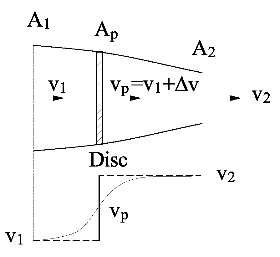
The advantages of ducted propellers over isolated propellers have been analyzed in Section 2.1. The following is the aerodynamic modeling of the ducted propellers. It is assumed that the density of the gas through the duct remains unchanged and the influence of viscosity is ignored. According to the continuity equation, the three sections in the Figure 5 satisfy v 1 A 1 = v p A p = v 2 A 2 , where V is the axial flow velocity of the flow tube, and A is the section area of the flow tube.
The tension, power and torque generated by the propeller can be calculated by BEMT theory above.
Tension coefficient expression
C T p = r = 0 r = 1 d C T p = 1 2 0 1 σ p C l r 2 d r ,
Power coefficient expression
C P d = r = 0 r = 1 λ d d C T d + 0 1 1 2 σ d C d r 3 d r ,
Torque coefficient expression
C M d = C P d / 2 π ,
The final propeller tension, power and torque are expressed as follows
T p = ρ A ( Ω R ) 2 C T p P d = ρ A ( Ω R ) 3 C P d M d = ρ A R ( Ω R ) 2 C M d ,
The factor q of duct tension ratio is also introduced to establish the total tension model of the lift duct as follows T d = T s + T p = q T d + T p .
The velocity at the propeller disc is v p . According to the momentum theory, the propeller tension and the power driving the propeller (equal the kinetic energy increased by the flow) can be expressed as
T p = ρ A 2 v 2 ( v 2 v 1 ) ,
P d = v p T p = ρ A 2 v 2 v p ( v 2 v 1 ) = 1 2 ρ A 2 v 2 ( v 2 2 v 1 2 ) = Δ E k i n ,
The useful work done by the propeller can be expressed as
W p = T p v 1 = ρ A 2 v 1 v 2 ( v 2 v 1 ) ,
Then, the propeller efficiency can be expressed as
η p = W p P p = ρ A 2 v 1 v 2 ( v 2 v 1 ) 1 2 ρ A 2 v 2 ( v 2 2 v 1 2 ) = 2 v 1 v 1 + v 2 = 2 1 + v 2 v 1 ,
In an ideal condition, the contracted wake area is A 2 = π a 2 R 2 , where a = 0.707 , A 2 / A p = 0.5 . In other words, under the ideal gas flow condition, the airflow velocity of the rear vena contracta of the duct can be obtained as v 2 = v 1 + Δ v / a 2 . At this time, v 1 is the axial free flow velocity, and the dimensionless velocity λ at the vena contracta of the flow tube can be calculated according to the BEMT theory mentioned above in relation (13), and then converted into v 2 .
v 2 = λ Ω R .
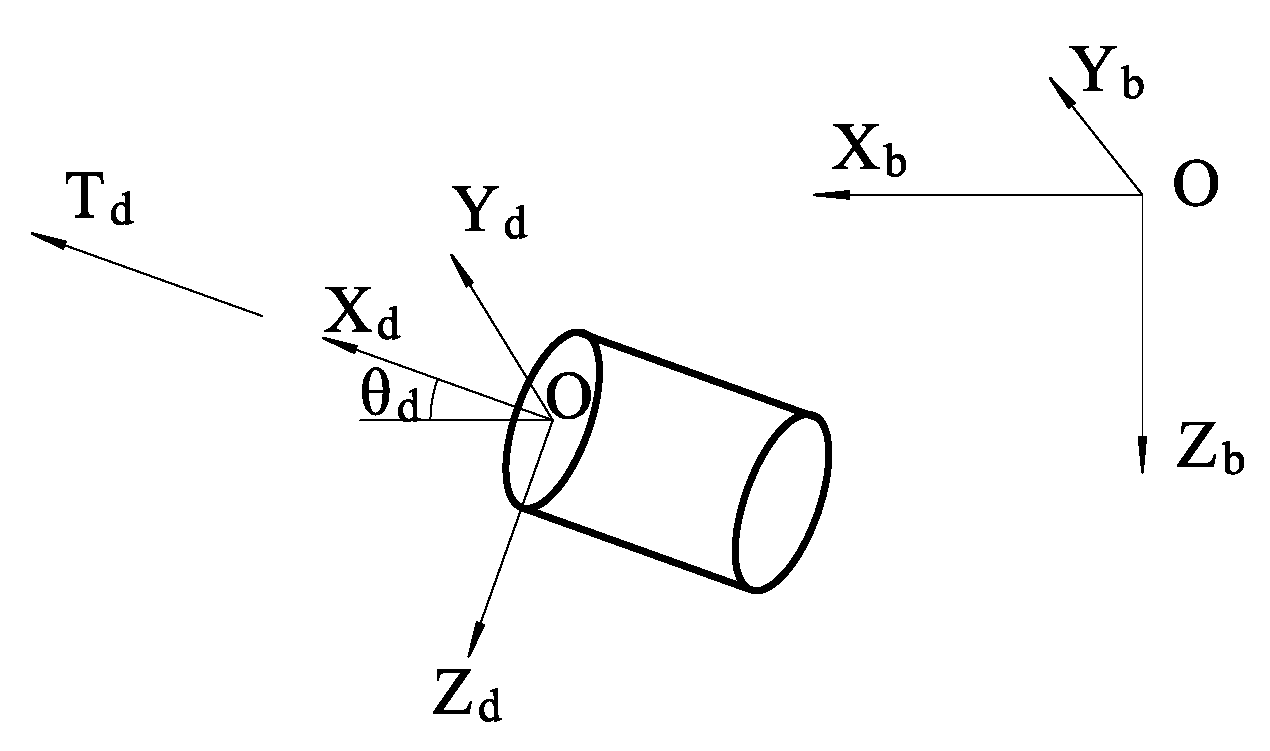
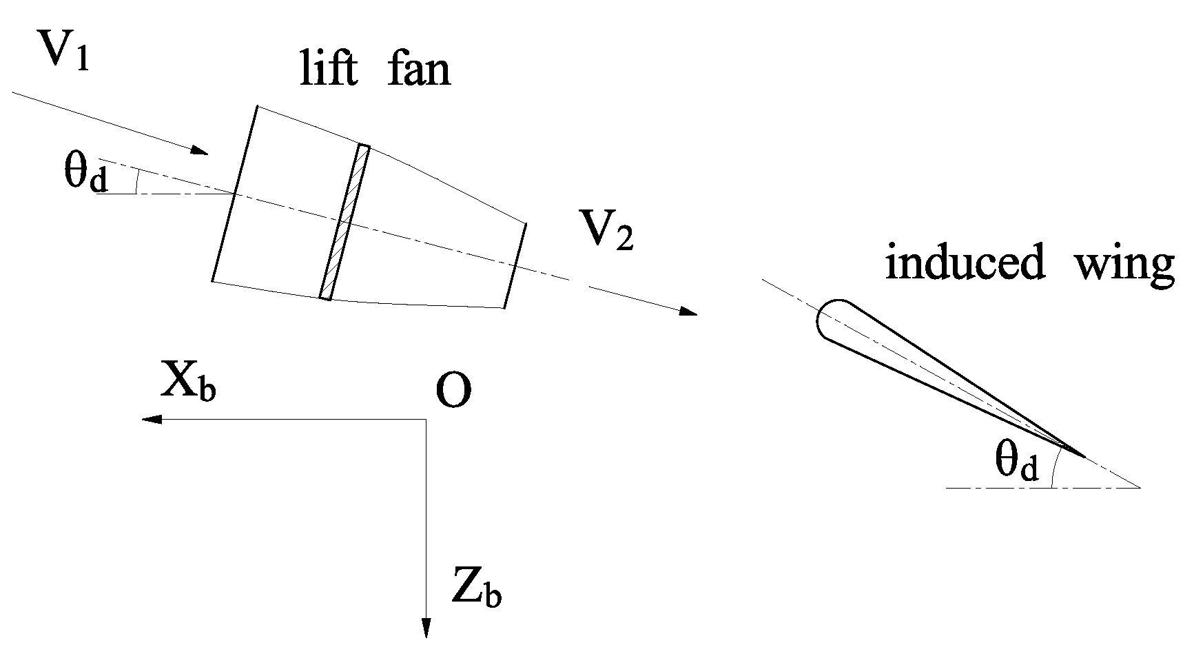
The aerodynamic force and torque of the lift duct were converted to the coordinate axis of the body, and the force and geometric relationship are shown in the Figure 6.
The coordinate transformation matrix of lift duct force and torque to the plane body coordinate system is R b d , of which the dimension is 3 × 3.
R b d = [ cos θ d 0 sin θ d 0 0 0 sin θ d 0 cos θ d ] ,
Under the coordinate system of the body, the force of the lift duct is expressed as: F b , d _ i = R b d F d _ i , where the dimension of F is 3 × 1.The lift duct torque is expressed in the body coordinate system as M b , d M _ i = R b d M d _ i , where the dimension of M is 3 × 1. The calculation of the torque generated by the lift duct force under the coordinate system of the body is obtained from M = L × F , and the specific calculation formula is as follows:
M b , d F _ i = ( x d _ i , y d _ i , z d _ i ) × F b , d _ i ,
where x, y, z is the coordinate position of the lift duct, and i is the imaginary number of the lift duct.

2.3. Induced Wing Aerodynamic Model

The induced wing surface is connected to the airframe, and its aerodynamic force is mainly determined by the airflow velocity at the outlet of the lift duct. The velocity at the outlet of the lift duct is taken as the free flow velocity of the induced wing surface, so as to simplify the establishment of the induced wing aerodynamic model.
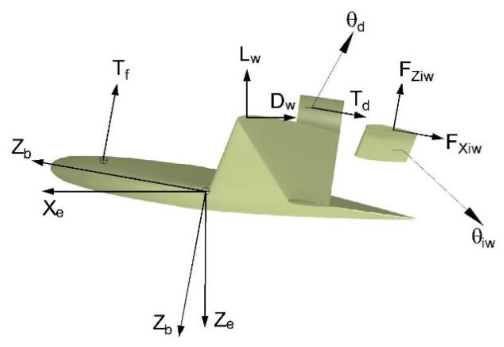
As shown in Figure 7, the aerodynamic force and moment of the induced wing surface can be obtained. In the airflow coordinate system, namely the coordinate system of the lift duct, the calculation is as follows [21]:
F X , i w = ( C D , 0 + C D , i ) q S ξ D F Z , i w = [ C L , 0 + C L α ( θ i w θ d ) ] q S ξ L M Y i w = C M ( θ i w θ d ) q S c ξ M ,
where C D , 0 is the zero-lift drag coefficient, C D , i is the induced drag coefficient, C L , 0 is the zero Angle of attack lift coefficient, C L α is the slope of the lift line, θ i w is the induced wing inclination angle, and θ d is the raised culvert inclination angle, ξ is the correction factor.
The transformation matrix from the lift duct coordinate system to the body coordinate system is R b d , and its aerodynamic force and torque are expressed as follows under the body coordinate system: F b , i w _ i = R b d F i w , M b , i w M _ i = R b d M i w _ i .
The calculation of the moment generated by the induced aerodynamic force of the wing on the airframe is based on the cross product of the position vector and force of the stress point under the body coordinate, that is M = L × F , and the specific expression is as follows: M b , i w F _ i = ( x i w _ i , y i w _ i , z i w _ i ) × F b , i w _ i , where x, y, z is the coordinate position of the induced wing, and i is the imaginary number of the induced wing.

2.4. Wing Aerodynamic Mode

Aerodynamic calculation of airfoil is generally obtained by CFD software or wind tunnel tests. To simplify the calculation, it is assumed that the aerodynamic force of the wing is not affected by the lift fan and the lift duct airflow, and the aerodynamic force and moment of the wing are functions of the variables such as angle of attack, sideslip angle, airspeed, air density, etc., which are expressed in the form of the conventional aerodynamic force and torque coefficient. Then the aerodynamic force and moment of the wing can be expressed as
D w = C D w q S w L w = C L w q S w M w = C M w c q S w ,
where, S w , c , q are the reference area, characteristic chord length and inlet flow pressure of the vertical take-off and landing UAV, respectively; C D w , C L w and C M w are aerodynamic force and torque coefficients obtained by CFD calculation.
In the XZ plane, under the condition of horizontal free flow, the lift and drag force of the wing can be transferred to the body coordinate system. In the symmetrical state, the pitching moment is consistent with the airflow coordinate and the body coordinate. The aerodynamic expression under the body coordinate is shown below:
F X b , w = L w sin θ D w cos θ F Z b , w = L w cos θ D w sin θ M Y b , w = M w ,
where θ is the pitch angle of the UAV.

3. Mathematical Model of Longitudinal Motion

It is assumed that the structure of UAV is rigid except lift fan and duct, and its dynamics modeling can apply Newton’s second law to conduct kinematic modeling of the components respectively, and finally convert the forces and torques of the components into the whole machine to establish the overall six degrees of freedom model.

3.1. Dynamic Model of Lift Fan and Lift Duct

In the coordinate system of the lift fan, according to the above aerodynamic model, the forces and torques of the lift fan are arranged as follows:
F X , f = T f M X , f = M f .
There may be deflection movement between the rising culvert and the body while hovering, so that the high-speed rotating duct generates gyroscopic torque acting on the body. The rotational motion of the duct around the center of mass is described as d h d / d t = M d , where h d is the moment of momentum of the duct to its center of mass, whose dimension is 3 × 1; M d is the resultant moment of the external force acting on the duct on its center of mass, whose dimension is 3 × 1.
When the duct coordinate system rotates with ω d , the derivative of the moment of momentum d h d / d t can be expressed as d h d / d t = δ h d / δ t + ω d × h d . Project the above equation into scalar form. Based on the existence of the rotational angular velocity ω x of the rotor inside the duct, ω y of its rotation around its y axis, and the constraints of the duct product of inertia I x y = I x z = I y z = 0 , the kinetic equation of the duct rotation around the center of mass was derived as follows
I x d ω x / d t = M x , d I y d ω y / d t = M y , d ( I y I x ) ω x ω y = M z , d .
In the coordinate system of the lift duct, according to the aerodynamics model, the forces and torques of the lift duct are arranged as follows
F X d _ i = T d _ i M X d _ i = M d _ i + M x , d M Y d _ i = M y , d M Z d _ i = M z , d .

3.2. Full Mechanical Model

Newton’s second law is used to express the force and moment as follows
m ( δ V / δ t + ω × V ) = F ,
δ h / δ t + ω × h = M ,
where F represents the resultant force; M represents the resultant moment; m represents mass; V is the velocity of motion; h represents the moment of momentum.
According to the assumption mentioned before, the above equation is expanded into the force and moment equations of the movement of the vertical take-off and landing UAV. The force consists of gravity, main wing aerodynamics, and induced wing aerodynamics, lift fan thrust, and lift duct thrust. The resultant moment consists of the aerodynamic moment of the main wing, the aerodynamic moment of the induced wing, the thrust moment of the lift fan and the thrust moment of the lift duct.
Then the six-degree of freedom motion equation of UAV can be expressed as follows
Dynamic translational equation of the center of mass
m ( d V x / d t + V z ω y V y ω z ) = F X b , g + F X b , w + F X b , i w + F X b , f + F X b , d m ( d V y / d t + V x ω z V z ω x ) = F Y b , g + F Y b , w + F Y b , i w + F Y b , f + F Y b , d m ( d V z / d t + V y ω x V x ω y ) = F Z b , g + F Z b , w + F Z b , i w + F Z b , f + F Z b , d } ,
Dynamic rotational equations of the center of mass
I x x d p / d t + ( I z z I y y ) q r I x z ( p q + d r / d t ) = M X b , w + M X b , i w + M X b , f + M X b , d I y y d q / d t + ( I x x I z z ) p r + I x z ( p 2 + r 2 ) = M Y b , w + M Y b , i w + M Y b , f + M Y b , d I z z d r / d t + ( I y y I x x ) p q + I x z ( q r d p / d t ) = M Z b , w + M Z b , i w + M Z b , f + M Z b , d } ,
From the formation process of the coordinate system of the body, the projection of the rotation angular velocity on the coordinate system of the body can be listed as follows:
[ p q r ] = [ ϕ ˙ ψ ˙ s i n θ θ ˙ c o s ϕ + ψ ˙ s i n ϕ c o s θ θ ˙ s i n ϕ + ψ ˙ c o s ϕ c o s θ ] ,
where, ϕ , θ , ψ are three Euler angles.
The position information in the earth coordinate can be obtained by the following formula:
x ˙ E = V x c o s θ c o s ψ + V y ( s i n ϕ s i n θ c o s ψ c o s ϕ c o s ψ ) + V z ( c o s ϕ s i n θ c o s ψ + s i n ϕ s i n ψ ) y ˙ E = V x c o s θ s i n ψ + V y ( s i n ϕ s i n θ s i n ψ + c o s ϕ c o s ψ ) + V z ( c o s ϕ s i n θ s i n ψ s i n ϕ s i n ψ ) z ˙ E = V x s i n θ + V y s i n ϕ c o s θ + V z c o s ϕ c o s θ } .

4. Balancing Calculation Method

In this paper, the balancing calculation is carried out for the hover state and transition state of UAV. The hover state is another equilibrium state of the UAV, in addition to straight and horizontal flight. The forces and torques acting on the UAV are changed by lifting fan, inducing wing surface deflection and increasing lift duct deflection. The force and geometry relationship of UAV need to be defined when the balance state of hover state is expanded in detail.
In the Figure 8, T represents the thrust, X, Y and Z represent the coordinates, and the sub-tables f, d, and i represent the lift fan, lift duct, and device number.
In the hover and transition stage, the force acting on the UAV includes five parts: lift fan thrust, lift duct thrust, induced wing aerodynamic force and main wing aerodynamic force. At this time, the force on the UAV is shown in the Figure 9.
It is assumed that the UAV faces the vertical plane in the hover stage, and the two sides of the lift duct will turn in opposite directions, and the moment will be balanced. Then, the internal force and torque of the UAV in the longitudinal plane can be expressed as follows according to previous formula:
m ( d V x / d t + V z ω y V y ω z ) = m g s i n θ + F X b , w + F X b , f + F X b , d + F X b , i w m ( d V y / d t + V x ω z V z ω x ) = 0 m ( d V z / d t + V y ω x V x ω y ) = m g c o s θ + F Z b , w + F Z b , f + F Z b , d + F Z b , i w } ,
d p / d t I x x + q r ( I z z I y y ) ( p q + d r / d t ) I x z = 0 d q / d t I y y + p r ( I x x I z z ) + ( p 2 + r 2 ) I x z = M Y b , w + M Y b , f + M Y b , d + M Y b , i w d r / d t I z z + p q ( I y y I x x ) + ( q r d p / d t ) I x z = 0 } .

5. Flight Strategy Calculation Case

Taking the UAV as an example, in the paper the transition window establishment, slow balance transition, X-axis open-loop and other aspects are calculated, and the corresponding calculation results is obtained. The case UAV has a total weight of 125 kg, a wingspan of 4 m, an average aerodynamic chord length of 0.85 m, an aircraft reference area of 3.4 m2, and a cruise wing load of 73 kg/m2.

5.1. Transition Window

The transition flight window can be divided into the transition front window and the transition terminal window. The transition front window is the flight status of hovering at a safe height after vertical take-off. The transition terminal window is the flight state that meets the safe level flight speed. The terminal window usually has three important flight parameters: flight speed, power thrust and aircraft attitude.
The window of the transition front section of the vertical take-off and landing UAV in this scheme is horizontal hovering at a safe height of 30 m. The terminal window can be calculated by the equilibrium equation. W = L = ρ / 2 V s 2 S C L max , V s a f e = 1.2 V s , M = 0 , where W is the weight of the aircraft; L is lift; ρ is the air density; V s is stall speed; S is the wing area; C L max is the maximum lift coefficient; V s a f e is the safe flight speed of the transition terminal window.
The balance equations of force and moment can be derived from the above model, where, the force equilibrium equation is T f cos θ + ( T d + F X i w ) sin ( θ d + θ ) = G ; Moment equilibrium equation is T f l f = T d sin θ d l d + F X i w sin θ d l i w , where l is moment arm.
In order to simplify the calculation, only the longitudinal balance problem is considered. Previous formula can be used to calculate the safe flight speed V s a f e = 34.70 m / s of the transition terminal window, and the lift duct deflection angle θ d , s a f e = 24.12 and attitude angle θ s a f e = 7.21 at this time. In other words, the flight speed is greater than the safe flight speed V s a f e , and the lift duct deflection angle is less than θ d , s a f e , and the attitude angle is stable at θ s a f e .

5.2. Slow Balancing State

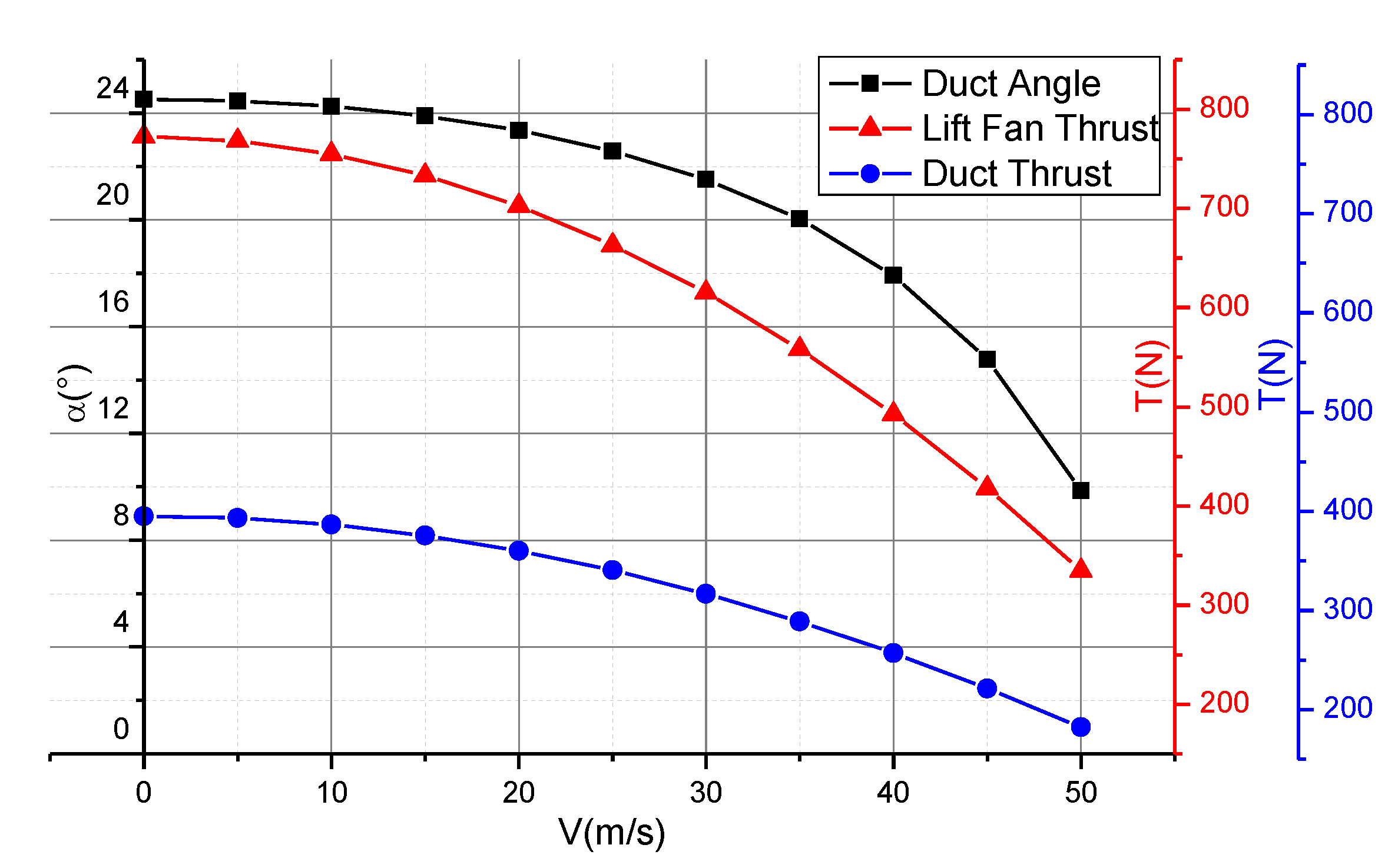
In the hover state, the forward flight speed is obtained by slowly adjusting the lift duct deflection angle, duct throttle and lift fan throttle, and the attitude pitch angle is chosen to be equal to the cruising pitch angle, which has value of 2 degrees, and its balance state is shown in the Figure 10.
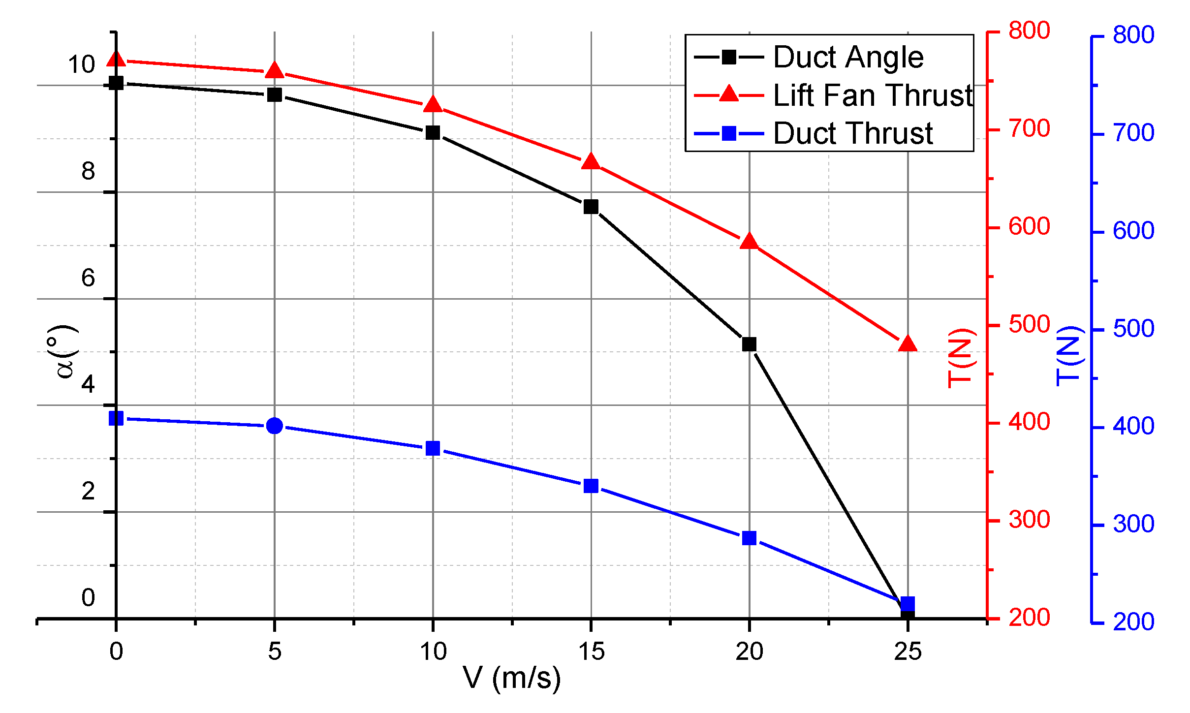
Similarly, the attitude angle θ s a f e = 7.21 at the end of the transition window is taken as the pitching attitude angle in the equilibrium state, and its balanced state is shown in the Figure 11.
Calculation results show that a certain forward speed is observed when duct is deflected slowly during transition from hovering to acceleration. Since aerodynamic force increases as speed increases, which causes increase of lift, the lift fan power in vertical direction decreases. Thrust is gradually reduced as the duct angle gradually shrinks to 0°. There exist two kinds of transition ways of pitch angle. When transition is performed with small pitching angle, the deflection angle of duct reduce to zero, and the speed of UAV meet requirement of transition. When transition is performed at large pitching angle and the deflection angle reduce to zero, the speed of UAV has not met the need of transition terminal window, so duct throttle should be enlarged to get better secure speed for horizontal flight.
In the process of slow balancing, by comparing different transition attitude angles, it can be seen that smooth transition to flat flight with small pitch angle can be observed, but the transition time is longer. The transition time of transition with large pitch angle is shorter, but the control parameters of the transition process change greatly, which is not stable compared with the transition of small pitch angle.

5.3. The X Axis Open-Loop Slow Transition

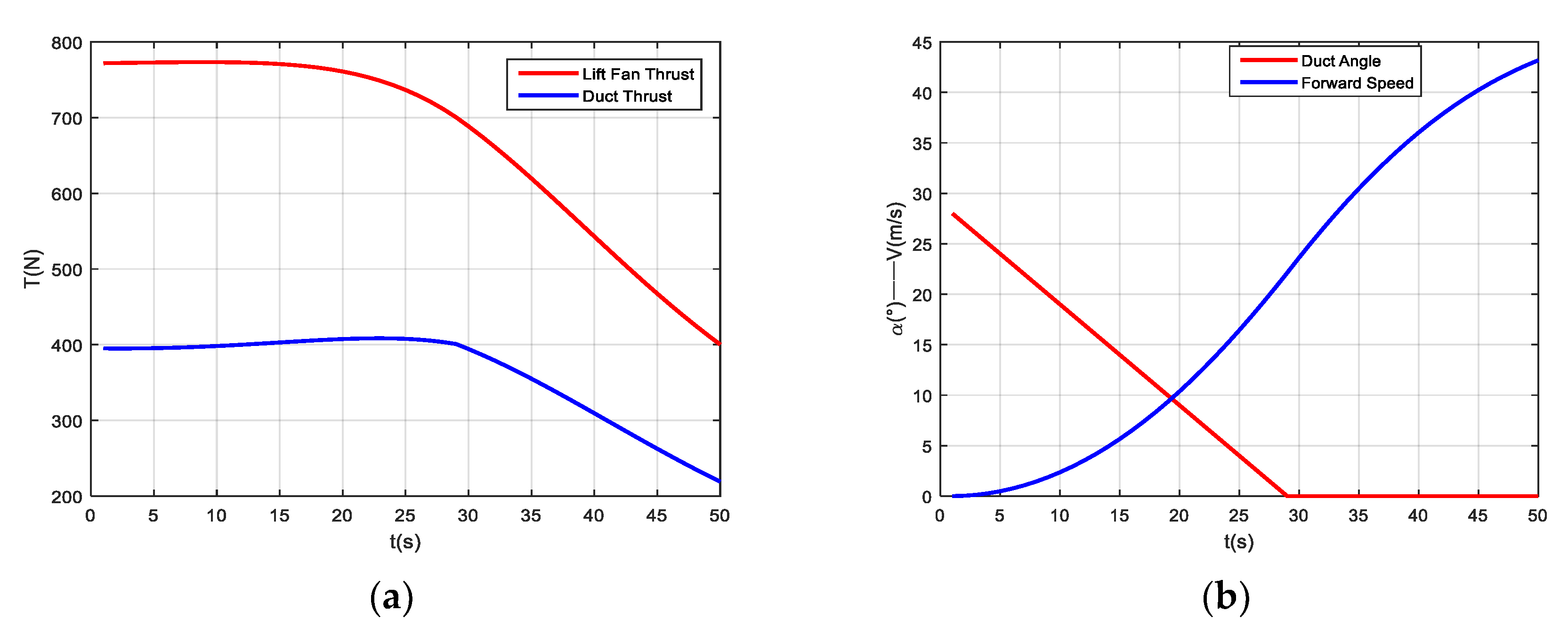
During longitudinal balancing and static moment balancing, the vertical grid of lift fan is not deflecting, and the X-axis limit is released, and the lift duct device is deflecting slowly with speed of 1 degree per second, in order to meet the transition terminal window speed of the UAV. The power and flight data are as shown in Figure 12:
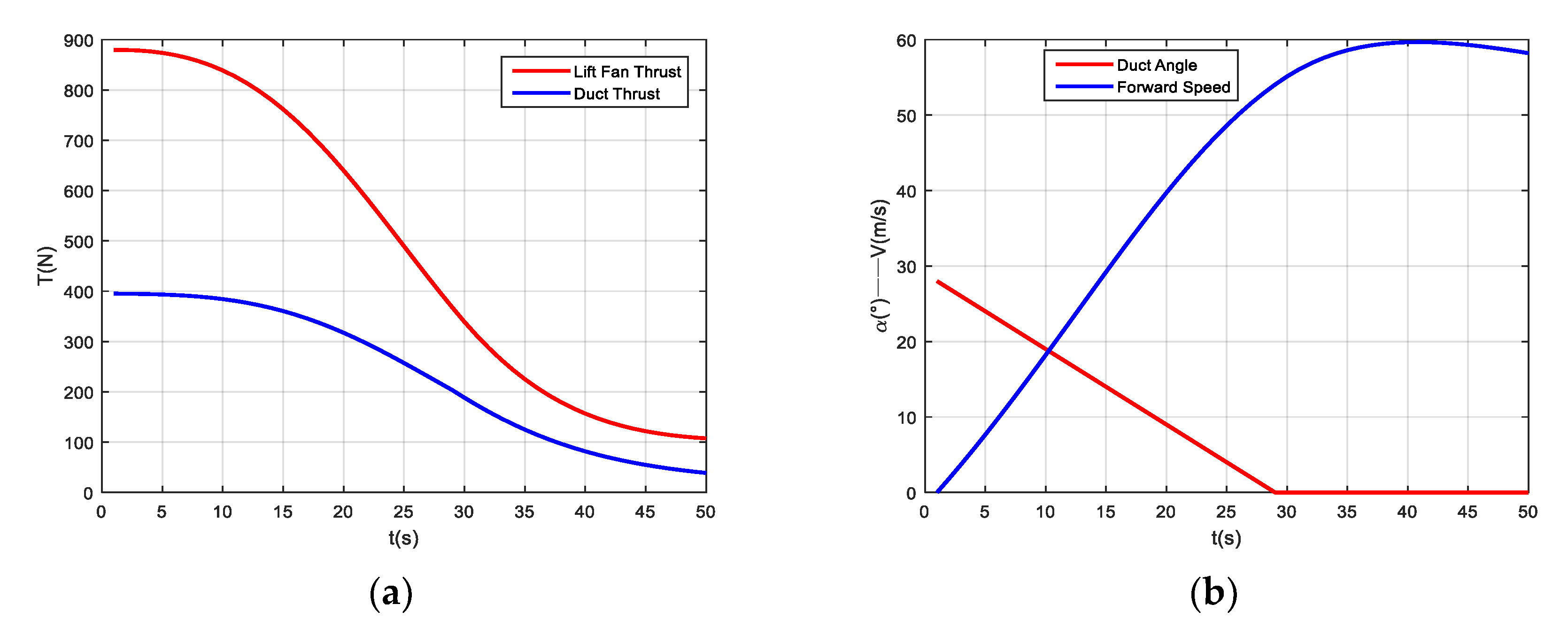
Similarly, during longitudinal balancing and static moment balancing, deflection angle of the vertical grid of lift fan is set to be 15 degree, the X-axis limit is released, and the lift duct device is slowly deflecting with rotating speed of 1°/s, until the UAV meets the speed of the transition terminal window. The power and flight data are as shown in Figure 13:
The calculation results show that the slow deflection power device, regardless of the aircraft’s dynamic characteristics, reduces the lift fan thrust gradually in 50 s. When the lift duct device deflects to a horizontal position, the aircraft speed gradually increases to the transition flight speed, reaching the transition terminal window and achieving stable and flat flight.
By comparing the calculation results of the deflection angles of the two lift fan grilles in the transition process, it can be seen that the deflection of the lift fan longitudinal grille makes the UAV transition to the terminal window faster, but the lift fan required for longitudinal balance has higher thrust and power.

5.4. The X Axis Open-Loop Rapid Transition

Considering the influence of dynamic characteristics, the VTOL UAV can reach the transition terminal window with different control methods. The induced aerodynamic force has very low sensitivity to the overall deflection of the induction device and can only change the direction of its force. However, the induced aerodynamic force is very sensitive to the induced wing deflection, which is manifested in the direction change and the non-linear change of the induced aerodynamic force.

5.4.1. Rapid Deflecting Duct and Induced Wing

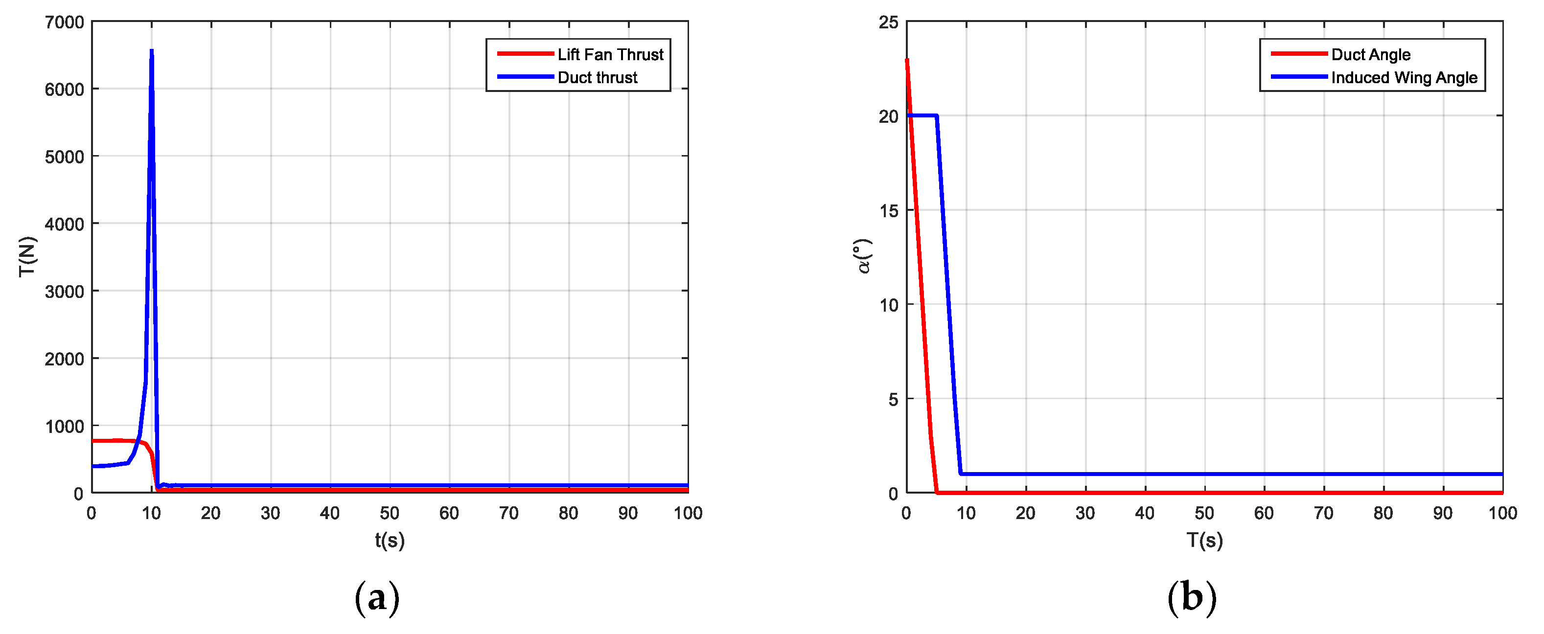
The simulation results show in Figure 14, when the induced wing and lift duct deflect with a relatively rapid speed of 5°/s, the lift duct completes deflection within 5 s, followed by 4 s for induced wing surface. Due to the induced aerodynamic force for sensitivity on the induced wing, the aerodynamic force rapidly decreases, and makes the lift duct balancing thrust increases rapidly, which is beyond the UAV balancing ability.

5.4.2. Rapid Deflecting Duct and Slow Deflecting Induced Wing

When the lift duct deflects quickly, the induced wing deflects to 0° at a speed of 0.75°/s. Under this kind of control mode, it just meets the maximum requirement of the duct thrust and can be transferred to the transition terminal window stably.

5.4.3. Arriving at Stall Speed Deflection Induced the Wing

In addition to the above continuous deflection duct and induced wing maneuvers, considering the sensitivity of the induced aerodynamic force to the induced wing deflection, the induced wing can be deflected after reaching the stall speed, and the deflection can be completed relatively quickly.
The simulation results show in Figure 15, when UAV arrives at stall speed, deflection of induced wing surface deflection can be completed within 10 s, balancing requirements at this time in the feasible range of duct and the lift fan. Within 10 s of the induced wing deflection, the duct thrust gets convergent oscillation. After the completion of the induced wing surface deflection, the duct thrust remains stable and the aircraft will fly steadily.

6. Discussion

The simulation results show that the UAV can achieve a stable transition flight within the constraints of the feasibility conditions (the power limit of lift fan and the lift duct). Both the slow transition and the fast transition have corresponding transition flight strategies. In the slow transition flight, the flight parameters change gently and the UAV flight state is stable. The rapid transition state, due to the rapid deflection of the induced wing surface, leads to the phenomenon of oscillation convergence in the lift duct, and finally the transition flight can be realized.
The aerodynamic model established in this paper is combined with the six-degree-of-freedom equation separately. This modeling method ignores the aerodynamic interference between the lift duct and the wing, that is, it is carried out under the assumption that they do not interfere with each other. Current work focuses on the longitudinal flight transition of UAV and the situation when there is no wind. The future research direction will focus on the lateral-directional flight of UAV and the stable transition strategy in the wind field. Although the paper is based on mathematical models, in fact, our universities, laboratories, and cooperative industrial units have reached the TRL5 [22] and have basically completed the production of prototypes.

7. Conclusions

The research is based on the assumption of ignoring the aerodynamic interference between pneumatic components. Based on the aerodynamic modeling of components, the overall dynamic model is established. After that, the transition corridor of VTOL UAV is studied in three aspects of flight trim, slow transition and fast transition. The above three aspects are simulated under different input conditions, such as different pitch angles and lift fan grid deflection angle. The results can be concluded as follows.
  • In the transition balancing process, the transition can reach the terminal window of the transition gently by balancing the transition with a small pitch angle 2°, but it takes a long time in the transition process.
  • By balancing the transition at a large pitch angle 7.21°, the high-speed deflection of the duct can be realized, but the control parameters change greatly, and the flight state is not smooth enough compared with the former.
  • In the slow transition process, the UAV can achieve a faster transition in 50 s through the deflecting lift fan longitudinal grille. However, this transition strategy requires a larger lift fan and bypass thrust and consumes more energy.
  • In the process of rapid transition, the rapid transition of UAV can be realized through the fast deflection of lift duct and the slow deflection of induced wing surface, so as to ensure smooth transition of UAV within 35 s.

Author Contributions

Conceptualization, C.W. and Z.Z.; methodology, C.W. and R.W.; software, C.W.; validation, C.W., Z.Z. and R.W.; formal analysis, C.W.; resources, Z.Z.; data curation, R.W.; writing—original draft preparation, C.W.; writing—review and editing, C.W.; supervision, R.W.; project administration, Z.Z.; funding acquisition, Z.Z.

Funding

This research was funded by EQUIPMENT PRE-RESEARCH PROJECT, grant number 41411020401.

Conflicts of Interest

The authors declare no conflict of interest.

References

  1. Tang, Z.F.; Xu, G.H. Key technology analysis of tilt-rotor aircraft. In Proceedings of the 16th National Helicopter Conference CAAC, Shanghai, China, 18 October 2000; pp. 29–32. [Google Scholar]
  2. Cao, Y. Research on Mathematical Modeling Method for Tilt Rotor Aircraft; Nanjing University of Aeronautics and Astronautics: Nanjing, China, 2012; pp. 11–14. [Google Scholar]
  3. Okan, A.; Tekinalp, O.; Kavsaoglu, M.S.; Armutcuoglu, O.; Tulunay, E. Flight mechanics analysis of a tiltrotor UAV, AIAA-99-4255. In Proceedings of the 24th Atmospheric Flight Mechanics Conference, Portland, OR, USA, 9–11 August 1999. [Google Scholar]
  4. Leishman, J.G.; Ananthan, S. Aerodynamic optimization of a coaxial proprotor. In Annual Forum Proceedings-American Helicopter Society; American Helicopter Society, Inc.: Fairfax, VI, USA, 2006; Volume 62, p. 64. [Google Scholar]
  5. Leishman, J.G.; Ananthan, S. An optimum coaxial rotor system for axial flight. J. Am. Helicopter Soc. 2008, 53, 366–381. [Google Scholar] [CrossRef]
  6. Yuksek, B.; Vuruskan, A.; Ozdemir, U.; Yukselen, M.A.; Inalhan, G. Transition flight modeling of a fixed-wing VTOL UAV. J. Intell. Robot. Syst. 2016, 84, 83–105. [Google Scholar] [CrossRef]
  7. Shi, X. Research on Longitudinal Flight Control of Transition of Tilt-Rotor Aircraft; Nanchang Hangkong University: Nanchang, China, 2017. [Google Scholar]
  8. Cao, Y.; Chen, R. Control strategy and balancing method of tilt-rotor aircraft. J. Nanjing Univ. Aeronaut. Astronaut. 2009, 41, 6–10. [Google Scholar]
  9. Wan, H. Simulation Study on Transition of Tilt-Rotor Aircraft; Nanjing University of Aeronautics and Astronautics: Nanjing, China, 2011. [Google Scholar]
  10. Zhang, J.; Ren, Z.; Deng, C.; Wen, B. Adaptive fuzzy global sliding mode control for trajectory tracking of quadrotor UAVs. Nonlinear Dyn. 2019, 97, 609–627. [Google Scholar] [CrossRef]
  11. Khaligh, S.P.; Fahimi, F.; Koch, C.R. A fast inverse kinematic solution for the nonlinear actuating mechanisms of a small-scale helicopter. Multibody Syst. Dyn. 2015, 35, 257–275. [Google Scholar] [CrossRef]
  12. Froude, W. On the Elementary Relation between Pitch, Slip, and Propulsive Efficiency; Technical Report Archive & Image Library: Washington, DC, USA, 1920; pp. 3–5. [Google Scholar]
  13. Gessow, A. Effect of Rotor-Blade Twist and Plan-Form Taper on Helicopter Hovering Performance; Technical Report Archive & Image Library: Washington, DC, USA, 1948. [Google Scholar]
  14. Liu, P. Air Propeller Theory and Its Application; Beijing University of Aeronautics and Astronautics Press: Beijing, China, 2006. [Google Scholar]
  15. Harun-Or-Rashid, M.; Song, J.B.; Byun, Y.S.; Kang, B.S. Inflow prediction and first principles modeling of a coaxial rotor unmanned aerial vehicle in forward flight. Int. J. Aeronaut. Space Sci. 2015, 16, 614–623. [Google Scholar] [CrossRef]
  16. Harun-Or-Rashid, M.; Song, J.B.; Chae, S.; Byun, Y.S.; Kang, B.S. Unmanned coaxial rotor helicopter dynamics and system parameter estimation. J. Mech. Sci. Technol. 2014, 28, 3797–3805. [Google Scholar] [CrossRef]
  17. Yoon, S.; Chan, W.M.; Pulliam, T.H. Computations of torque-balanced coaxial rotor flows. In Proceedings of the 55th AIAA Aerospace Sciences Meeting, Grapevine, TX, USA, 9–13 January 2017; p. 52. [Google Scholar]
  18. Leishman, J.G. Principles of Helicopter Aerodynamics, 2nd ed.; Cambridge University Press: New York, NY, USA, 2006. [Google Scholar]
  19. Zheng, Z.; Zhou, Z. Analysis of lift fan estimation model in vertical take-off and landing aircraft design. Flight Mech. 2010, 28, 21–23. [Google Scholar]
  20. Kriebel, A.R.; Sacks, A.H.; Nielsen, J.N. Theoretical Investigation of Dynamic Stability Derivatives of Ducted Propellers; Ft. Belvoir Defense Technical Information Center: Fort Belvoir, VA, USA, 1963. [Google Scholar]
  21. Fang, Z. Flight Dynamics of Aircraft; Beijing University of Aeronautics and Astronautics Press: Beijing, China, 2005. [Google Scholar]
  22. Pinilla, L.S.; Rodríguez, R.L.; Gandarias, N.T.; de Lacalle, L.N.L.; Farokhad, M.R. TRLs 5–7 Advanced Manufacturing Centres, Practical Model to Boost Technology Transfer in Manufacturing. Sustainability 2019, 11, 4890. [Google Scholar] [CrossRef] [Green Version]
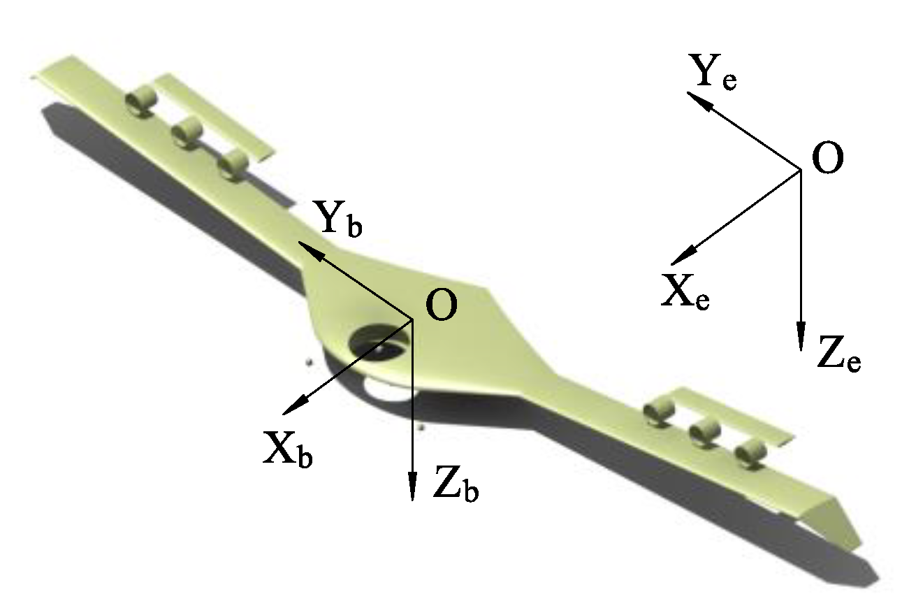
Figure 1. Body coordinate system.
Applsci 09 04937 g001
Figure 2. Flow model used for the BEMT (Blade Element Moment Theory) analysis of a coaxial rotor system.
Applsci 09 04937 g002
Figure 3. Tension factor fitting curve.
Applsci 09 04937 g003
Figure 4. Lift fan force diagram.
Applsci 09 04937 g004
Figure 5. Schematic diagram of speed and pressure before and after the disc.
Applsci 09 04937 g005
Figure 6. Diagram of force and geometry of lift duct.
Applsci 09 04937 g006
Figure 7. The geometrical relation between lift duct and induced duct.
Applsci 09 04937 g007
Figure 8. Force, moment, and some geometrical dimensions of UAV.
Applsci 09 04937 g008
Figure 9. Force and moment on the UAV in transition flight.
Applsci 09 04937 g009
Figure 10. Lift fan and lift duct state curve when pitch angle is 2°.
Applsci 09 04937 g010
Figure 11. Lift fan and lift duct state curve when pitch angle is 7.21°.
Applsci 09 04937 g011
Figure 12. (a) Slow transition of lift fan and lift duct thrust state; (b) Slow transition of forward speed and lift duct deflection.
Applsci 09 04937 g012
Figure 13. (a) Deflection grille slow transition of lift fan and lift duct thrust state; (b) Deflection grille slow transition of forward speed and lift duct deflection.
Applsci 09 04937 g013
Figure 14. (a) Rapid transition of lift fan and lift duct thrust state when rapid deflecting duct and induced wing; (b) Rapid transition of forward speed and lift duct deflection when Rapid deflecting duct and induced wing.
Applsci 09 04937 g014
Figure 15. (a) Rapid transition of lift fan and lift duct thrust state when arriving at stall speed deflection induced the wing; (b) Rapid transition of forward speed and lift duct deflection when arriving at stall speed deflection induced the wing.
Applsci 09 04937 g015