Article

A High Signal–Noise Ratio UWB Radar for Buried Pipe Location Using Golay Complementary Sequences

1
Key Laboratory of Advanced Transducers & Intelligent Control System, Ministry of Education and Shanxi Province, Taiyuan University of Technology, Taiyuan 030024, China
2
College of Physics & Optoelectronics, Taiyuan University of Technology, Taiyuan 030024, China
*
Author to whom correspondence should be addressed.
Appl. Sci. 2019, 9(23), 5090; https://doi.org/10.3390/app9235090
Submission received: 14 November 2019 / Revised: 21 November 2019 / Accepted: 22 November 2019 / Published: 25 November 2019

Abstract

:
A Golay-based ultra wideband ground penetrating for underground pipes location is proposed and experimentally demonstrated. Golay complementary codes with the code length of 1024 and frequency of 1 GHz are used as the probe signals. The two-dimensional image of the buried pipes is achieved by a correlation method and a back-projection algorithm. The experimental results show that both the plastic pipe and metallic pipe can be located with a range resolution of 10 cm. Furthermore, as the Golay complementary sequences are a pair of complementary sequences, the sum of their correlation function yields twice the value of the peak at the target position and zero elsewhere. Thus, compared with the stepped frequency signal radar or chaotic signal radar, the Golay-based radar can significantly improve the signal–noise ratio and has the capability of deep detection.

1. Introduction

Detection and location of underground pipes before excavation work is extremely important. It can ensure faultless working processes and minimize the impacts on the existing pipes in the intervention area. Once the buried pipes are damaged, the undesirable fluid losses due to leaks can cause enormous environmental and economic repercussions. Ultra-wideband (UWB) ground penetrating radar (GPR) [1,2,3] as one of the non-destructive techniques [4,5,6,7,8] to locate the underground pipes attracts increasing attention because it is capable of accurately locating both metallic and non-metallic pipes without prior knowledge. However, conventional UWB GPR utilizes short pulse as the transmit signals, which leads to a tradeoff between the resolution and the detection distance.
In order to expand the detectable range without degrading the resolution, large time-bandwidth signals are used as the transmit signals in recent years, such signals include frequency modulated continuous wave (FMCW) signals [9,10,11], stepped frequency signals [12,13,14], code signals [15,16,17], and chaotic signals [18,19,20]. UWB GPR based on FMCW signals or stepped frequency signals suffer from having strong sidelobes [21], thereby resulting in low signal–noise ratio (SNR). To suppress these undesired sidelobes, different mismatched filters have been reported in the literature [22,23,24]. Unfortunately, these sidelobes suppression techniques come at the cost of signal–noise ratio (SNR) loss and resolution reduction [25]. Pseudorandom binary sequences (PRBS or m-sequences) have low sidelobes and exhibit good correlation properties. Additionally, their sidelobes can be further reduced by extending the length of the PRBS [26]. Thus, the UWB GPR based PRBS can enhance the SNR [27]. Extensive studies show chaotic signals possess many properties that make them an attracting candidate for radar system design [28,29,30]. The random nature of chaotic signals shows good correlation properties, which can improve the SNR of radar [31]. Although, both PRBS and chaotic signals are considered good options in terms of their low sidelobes, these two signals are not ideal choices if we take sidelobe level into account.
Golay complementary sequences are a pair of equal length sequences that have the following property: when their correlation functions are algebraically added, their sidelobes are canceled while the correlation peak is double of that individual one [32]. Therefore, the Golay complementary sequences are very suitable for GPR. Pace et al. used Golay complementary sequences to encode Costa frequency hopping continuous waveforms. Their results indicated the improvement in sidelobe compared to the same frequency hopping waveform encoded with the Barker code [33]. Utilizing Golay complementary sequences as the probe signal and combining with single sideband transmission, Alejos et al. improved the existing noise radar system. They compared the influence of noise on the PRBS-based radar and Golay-based radar in terms of peak sidelobe, secondary sidelobe, and integrated sidelobe values. Their theoretical and experimental results in free space demonstrated the Golay codes offered better performances even when the sequence length ratio of PRBS code and Golay codes is 2:1 [34,35,36,37,38]. Using Golay codes with a carrier of 12 MHz to degrade the sidelobe and a time-gain amplifier in the receiver to obtain the weak returned signal from the deep target, two experimental results of Xie et al. demonstrated the detection performance of the proposed low frequency coded GPR [39].
In this paper, Golay complementary sequences are introduced for underground pipe location. A Golay complementary sequences generator with tunable code length and frequency is achieved and utilized as probe signals. The buried depth of the plastic pipe or metallic pipe can be obtained by the correlation function. Then two-dimensional imaging of buried pipes is achieved by utilizing the back projection (BP) algorithm, which is beneficial for target recognition. The experiments are carried out to locate the underground plastic pipe and metallic pipe. Furthermore, we compare the performance of different UWB radar systems. This paper is organized as follows: Section 2 provides the Golay-based radar system and its measurement principle. Section 3 introduces the generation and characteristics of the Golay complementary sequences. Section 4 shows the experimental results of underground pipe location. Section 5 shows the comparison results among proposed radar, chaotic radar and stepped frequency signal radar. Section 6 discusses the effect of the frequency dispersion on the approach and gives the conclusions.

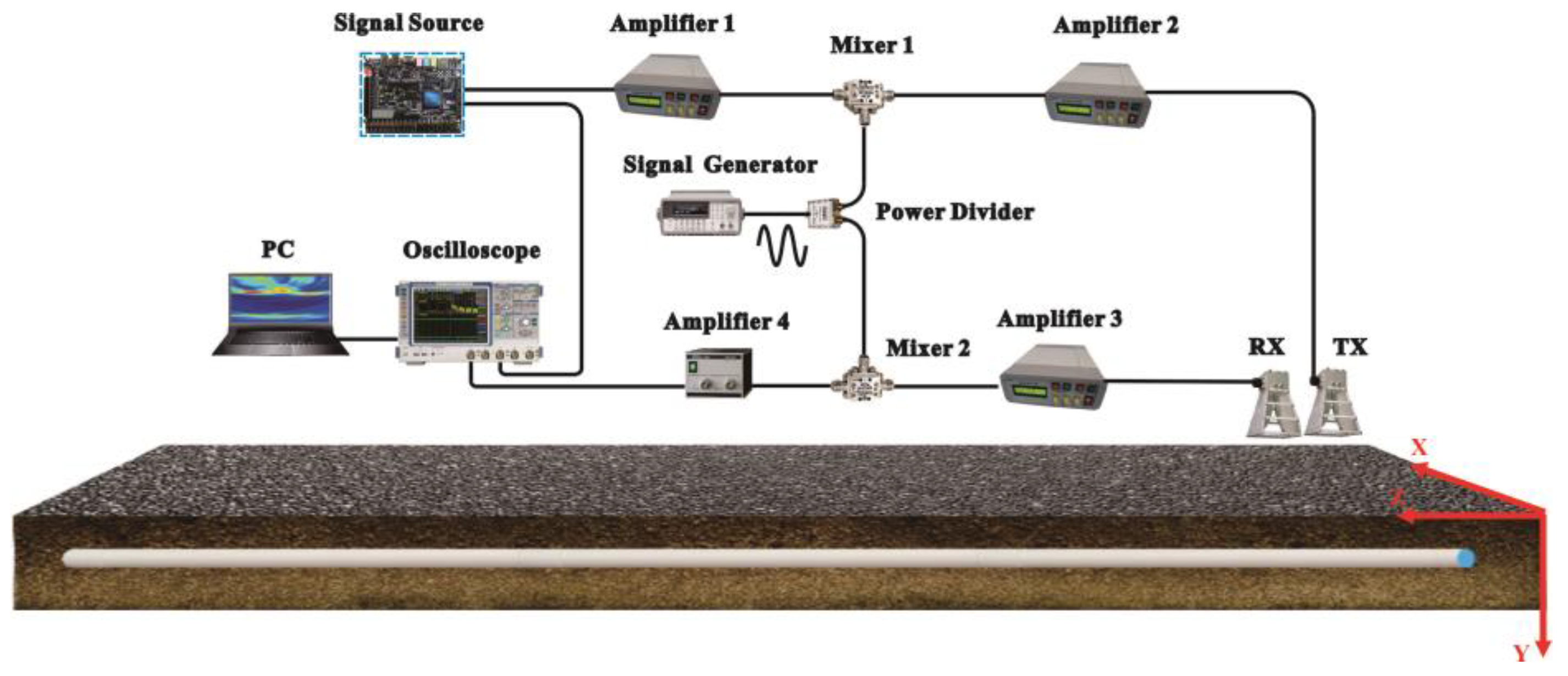
2. Radar System and Measurement Principle

The experimental setup of the underground pipe locating utilizing the Golay complementary sequences is shown in Figure 1. The signal source (Intel, Santa Clara, CA, USA) generated a pair of high rate Golay complementary codes: code A and complementary code B. Then the code A or code B was divided into two paths. One served as the reference signal and the other serves as a probe signal. The probe signal is first amplified by a 25 dB amplifier 1 (CONQUER, Beijing, China). Then it was up-converted by a mixer 1 (Marki, Morgan Hill, CA, USA), amplified by a 10 dB amplifier 2 (CONQUER, Beijing, China), and transmitted by one of the wideband horn antenna (TX). The other wideband horn antenna (RX) received the echo signal and sent it down to a 20 dB gain amplifier 3 (CONQUER, Beijing, China). After being further amplified by a low noise amplifier 4 (Agilent, Santa Clara, CA, USA) via the mixer 2 (Marki, Morgan Hill, CA, USA), the echo signal, together with the reference signal were recorded by a real-time oscilloscope. Then we utilized a computation to process data and display the results. In the experiment, the operating frequency range of TX or RX is from 1GHz to 18 GHz and its reported gain is 11 dBi. The signal generator generated 3.4 GHz local signal for mixer 1 and mixer 2. The average power of the transmitting signal through TX was −12 dBm.
The proposed radar system utilizes a pair of high rate Golay complementary codes as the probe signals. The depth of the buried pipe can be obtained by correlating the corresponding reference signal and the echo signal. The respective correlation functions are given by:
V Acorr ( t ) = V Aref ( t ) V Aech ( t ) = k δ ( t τ )
V Bcor r ( t ) = V Bref ( t ) V Bech ( t ) = k δ ( t τ ) ,
where ⊗ is the correlation operator, τ is the time delay between the echo signal and the reference, and k is the correlation coefficient. VAcorr(t), VAref(t), and VAech(t) respectively denote the correlation signal, reference signal, and echo signal of code A. VBcorr(t), VBef(t), and VBech(t) respectively denote the correlation signal, reference signal, and echo signal of code B. We can obtain the buried depth of pipe from the position of the correlation peak.
Although the depth of the pipe can be obtained from either correlation of code A or correlation of code B. However, by adding the correlation of code A to the correlation of complementary code B, we can obtain that the sum of the two correlation functions has a peak value of twice code length and a sidelobe level of zero, which is beneficial for pipe location. The sum of the two correlations VA+B(t) is given by:
V A + B ( t ) = V Acorr ( t ) + V Bcorr ( t ) = 2 k δ ( t τ ) .
Then back projection (BP) algorithm is used to achieve the two-dimensional (2D) imaging of the underground pipes. The TX and RX move along a line with a constant spacing. The whole imaging region is divided into P pixels. For any pixel point p, the signal Ip(t) equals the sum of all envelopes of VA + B(t) at the corresponding time delay. Ip(t) can be written as:
I p ( t ) = n = 1 M | V A + B ( t ) | δ ( t 2 R np v ) ,
where Rnp is the distance from pixel p to the n-th TX/RX, v is the velocity of underground wave, M is the unit of array elements. If the pipe is located at pixel p, the energy at this position will be enhanced. Otherwise, it will be small and can be regarded as the background. The entire imaging area I can be written as:
I = p = 1 P I p ( t ) .

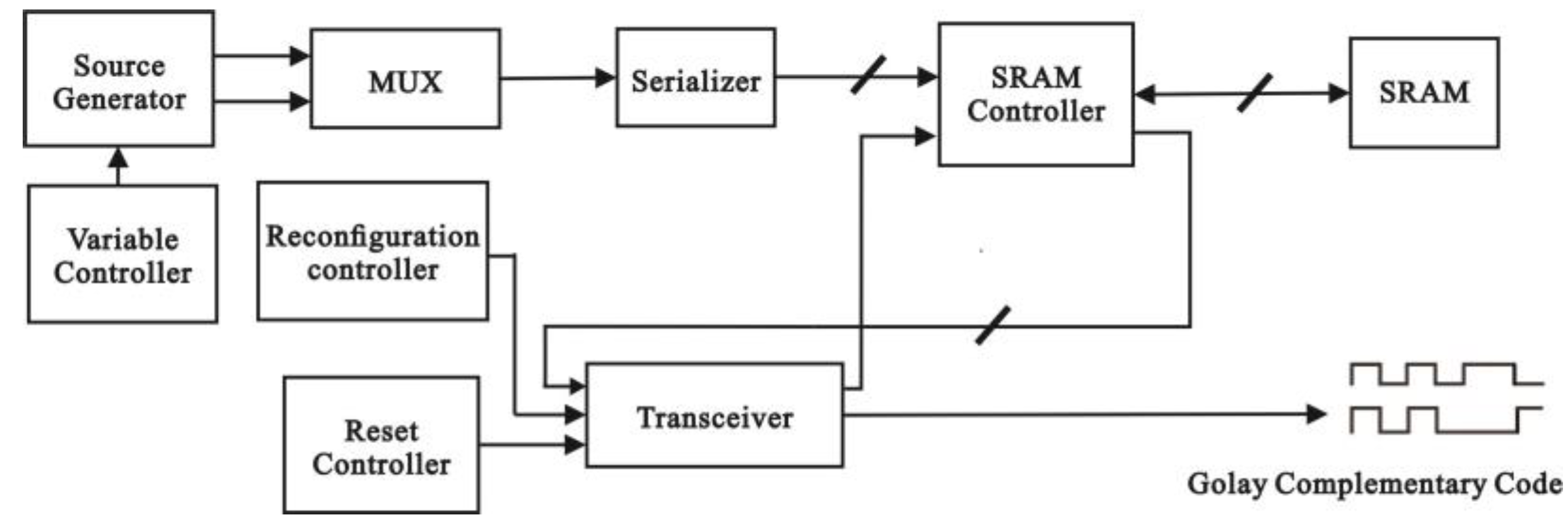
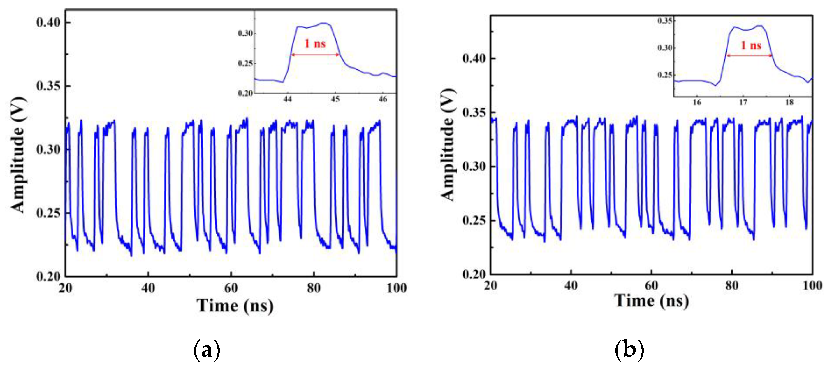
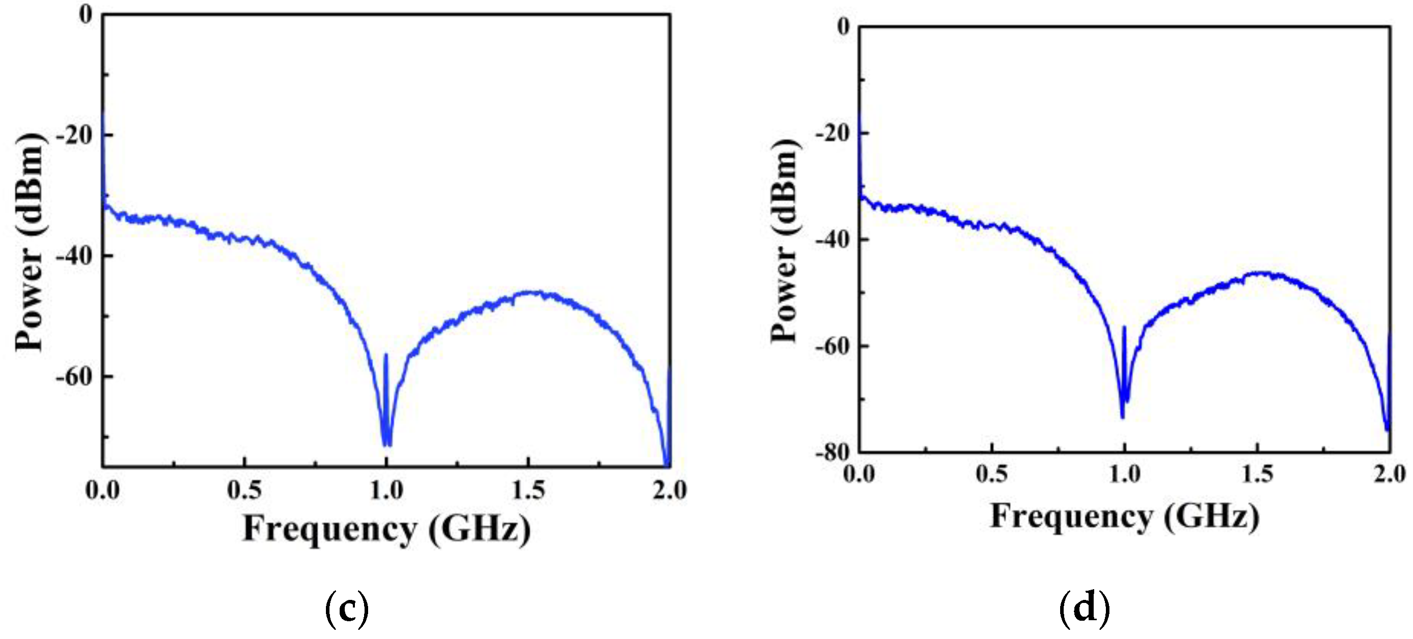
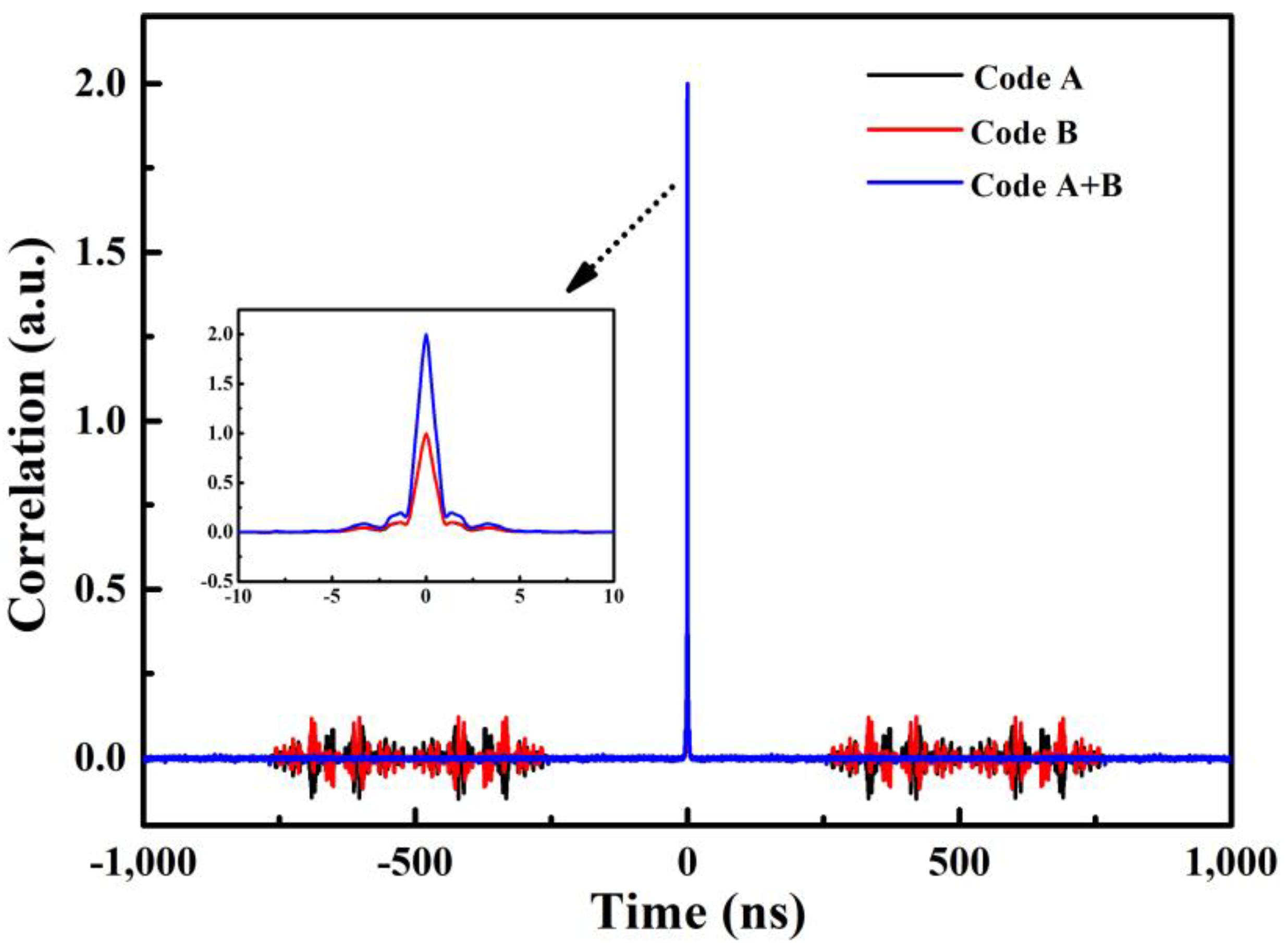
3. Generation and Characteristics of the Probe Signal

The Golay complementary codes are generated from a field-programmable gate array (FPGA, intel Cyclone V 5CG) and the corresponding hardware structure diagram is shown in Figure 2. The source generator generates a pair of low rate Golay complementary codes: code A and code B. Their code lengths were controlled by the variable controller. Through the multiplexer (MUX, Company, City, State Abbreviation if USA or Canada, Country), code A or code B was selected and then sent into serializer (Company, City, State Abbreviation if USA or Canada, Country), which was used to convert data into large bitwidth parallel data. The large bitwidth data was stored in the static random access memory (SRAM) using the SRAM controller (Company, City, State Abbreviation if USA or Canada, Country). When the transceiver receives a reset signal from the reset controller, it controls the SRAM controller and reads the data. After deserializing in the transceiver, the data is output through the low voltage differential signaling (LVDS) interface to obtain a high rate Golay complementary code. In the hardware implementation diagram, the reconfiguration controller was used to adjust the signal transmission rate. By using this FPGA board, Golay complementary codes with a maximum code length of 219 and tunable frequency between 615 MHz and 3.125 GHz can be achieved. In actual use, the signal frequency and code length can be flexibly selected according to the requirements of the detection environment. In our experiment, the code lengths of the Golay complementary codes are 1024 and the frequencies are 1 GHz.
Figure 3 and Figure 4 show the properties of Golay complementary codes. The time series of a pair of Golay complementary codes are shown in Figure 3a,b. The amplitude of code A and complementary code B are 0.1 V, and a symbol period of each code is 1 ns. Figure 3c,d show the power spectrums of codes A and B, respectively. The autocorrelation of each code is shown in Figure 4. The individual autocorrelation of A or B exhibits sidelobes. However, when the two autocorrelations were added together, the peak value was twice its single autocorrelation, whereas the sidelobes cancel exactly.

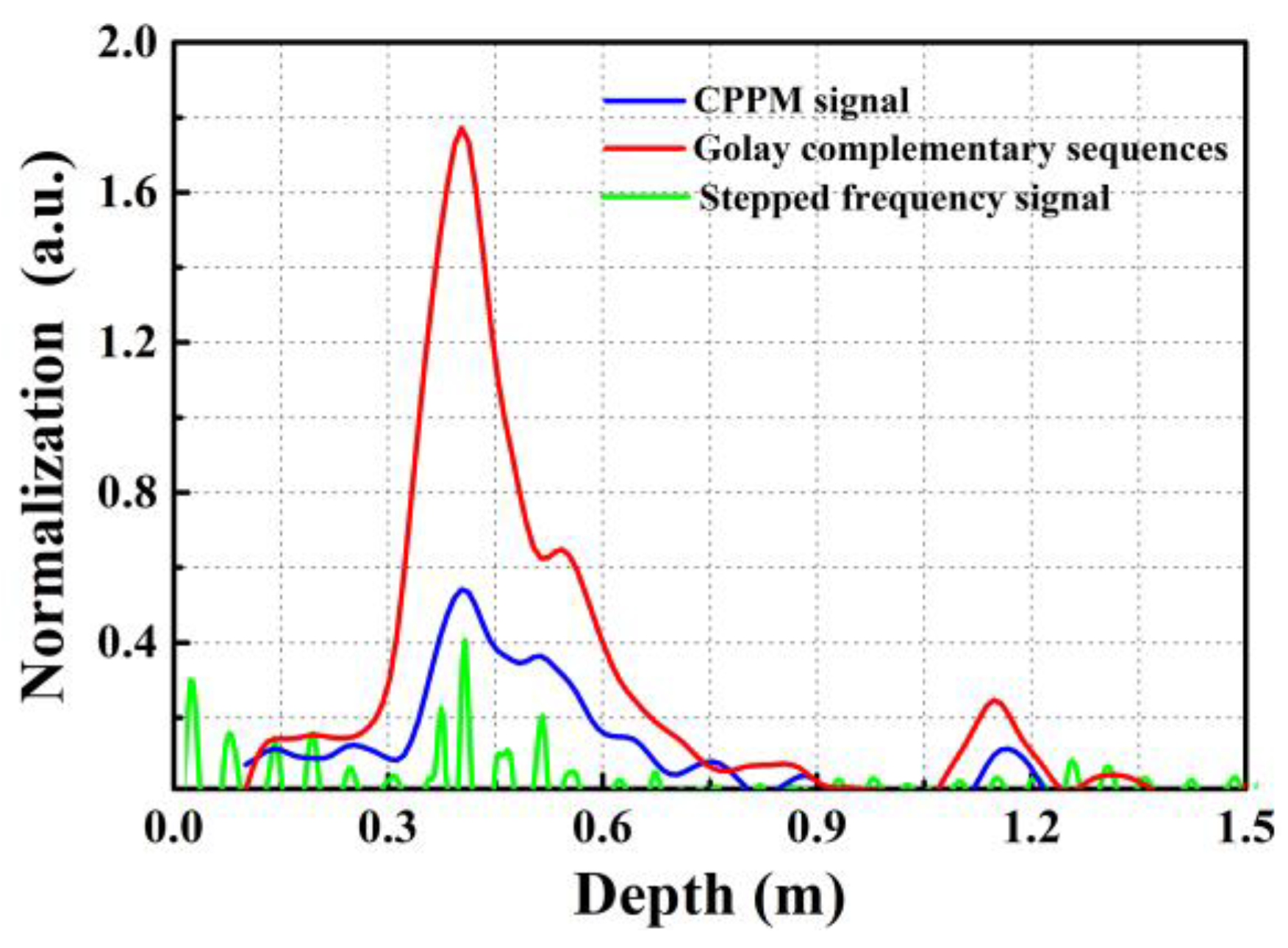
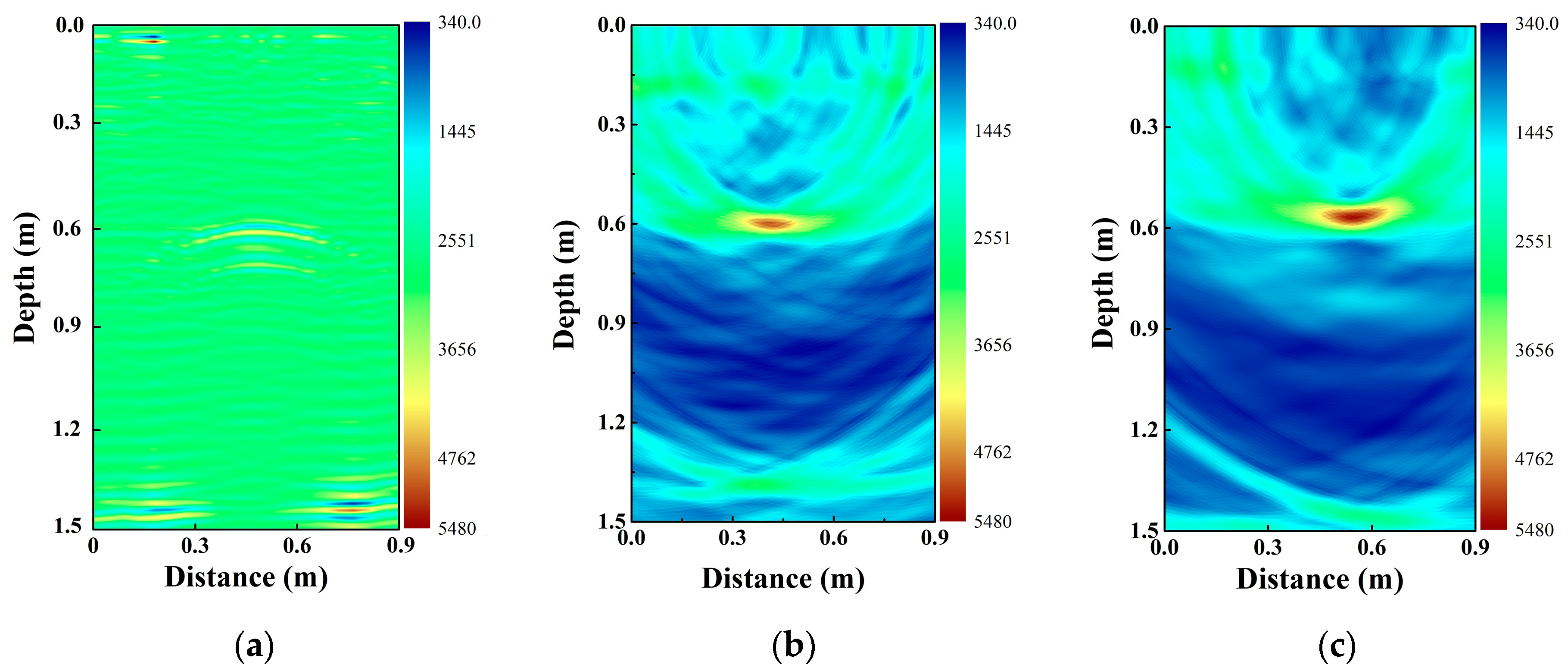
4. Experimental Results

We experimentally locate underground pipe utilizing Golay complementary sequences. A 2.00 m × 1.50 m × 1.50 m tank filled with dry sand is used to simulate the experimental scenario. As the tank has steel structures, we attach absorbing materials to the surface of the steel to eliminate its strong interference. In our experiment, the TX and RX are placed on the sand with the distance between TX and RX of 2 cm. They were moved along the x-axis with a step size of 5 cm, as shown in Figure 1. In addition, we utilized average filtering to inhibit the direct wave reflected from the surface and crosstalk between TX and RX. The wave velocity in our experiment is about 2 × 10⁸ m/s, which is deduced from the delay time and the known-depth of the pipe. The range resolution of the Golay-based radar system was about 10 cm. It is estimated by v/2Bw, where v is the wave velocity of the electromagnetic wave in the transmission media, Bw is the bandwidth of the signal. The parameters of the pipes used in the experiments are shown in Table 1. All of these pipes were filled with air.
Figure 5 shows the experimental results. The circles in the figure represent the actual profile of pipes. The coordinates correspond to the top position of the buried pipe. We first located two plastic pipes (P1 and P2) buried 85 cm and 60 cm below the sand surface. The result is shown in Figure 5a, which demonstrates plastic pipes buried at different depth can be located. In Figure 5a, the reflection appearing at a depth of approximately 135 cm is from the steel of the tank bottom. Similarly, when two metallic pipes (M1 and M2) buried at different depths, from the corresponding 2D image, we can also clearly identify their positions. Furthermore, to give a better description of the real condition, we locate two different material pipes (P1 and M2) simultaneously. Figure 5c shows that both the positions of the plastic pipe and metallic pipe can be visible and each position accords with the real value. The above experimental results illustrate that the Golay complementary sequences can successfully be applied to locate underground pipes. In addition, from Figure 5b,c we can observe that due to the existence of the metallic pipe, the reflection of the other pipe around metallic one will be weakened.

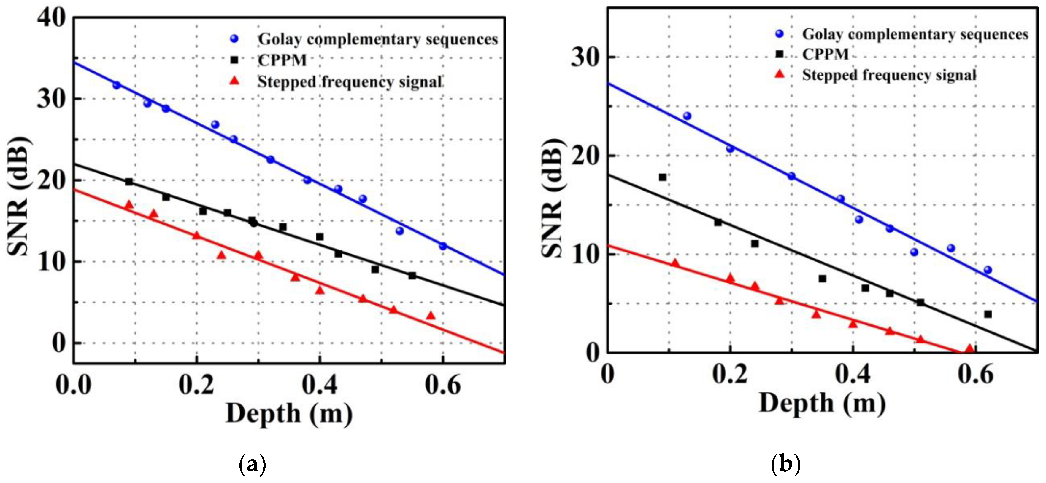
5. Detection Performance

To analyze the performance of the proposed Golay complementary sequences radar system, we give the comparison among the proposed radar, chaotic radar, and stepped frequency signal radar. Here, the vector network analyzer was regarded as the stepped frequency signal radar whose modulated frequency range is from 1.80 GHz to 5.00 GHz. The chaotic radar was based on the chaotic pulse position modulation (CPPM) signal. CPPM was used to generate a sequence of pulse distanced by time intervals generated by a chaotic map [40]. Compared with the chaotic pulse amplitude modulation signal, it had a low crest factor and thus had great robustness to external noise [41]. We have a detailed description of the CPPM signal radar in our previous work [42]. In this paper, the CPPM signal with 1.00 GHz bandwidth is up-converted to 2.40–4.40 GHz. Then we used the up-converted signal as the probe signal. Besides, other parameters in these three radar systems were the same.
Figure 6 shows a comparison result of normalization curves. The plastic pipe was buried at 40 cm in three radar systems. In the normalization curves, the peak position presents the buried depth of the pipe. The higher this peak value, the easier it was to identify the target. Thus, observing Figure 6, we obtain that the peak of the curve based on Golay complementary sequences is remarkably higher than that based on the CPPM signal or stepped frequency signal when the pipe was buried at the same depth. Besides, by using chaotic radar and Golay-based radar, the reflection of the tank bottom at 120 cm can also be clearly observed. While it cannot be obtained by using stepped frequency signal radar.
Figure 7 shows the SNR of the normalization curve as a function of the buried depth. The SNR is defined as follows [43]:
S N R = 20 log A S A N ,
where AS refers to the amplitude of the target reflection peak and AN refers to the amplitude of the maximum noise peak. From Figure 7a,b, we can see that the SNR obtained from the Golay complementary sequences radar is also higher than that of CPPM signal radar or stepped frequency signal radar at the same buried depth, no matter whether the target is a plastic pipe or metallic pipe. The results mean the proposed radar system was capable of detecting deeper buried pipe. Additionally, the SNRs of stepped frequency signal radar, CPPM signal radar, and Golay-based radar at 40 cm (correspond to the results in Figure 6) are 2.65 dB, 6.61 dB, and 13.44 dB, respectively.
Furthermore, to intuitive analysis of the performance of these three radar systems in the underground pipe location, 2D images are given. Figure 8a–c show the 2D images of stepped frequency signal radar, chaotic radar, and Golay complementary sequences radar, respectively, when the same plastic pipe is buried at about 60 cm. Comparing the 2D images, we obtain that although the position of pipe can be seen in these three figures, Figure 8c shows the greatest contrast between the target and the surroundings. It means the value at this position is the largest in these three figures, which is beneficial to locate the deeper buried pipe. This result is consistent with previous conclusions obtained from Figure 6 and Figure 7.

6. Discussions and Conclusions

For the UWB radar system, the frequency dispersion is an important issue, which affects the performance of radar imaging. The UWB signal traveling through a dispersive medium will arise the appearance of Brillouin precursors that broaden the pulse width and drift the power of the signal towards lower frequency bands [44]. The precursor waveforms superimposed to the traveling waveform result in inaccurate processing in the receiver system. To mitigate these impairments, two frequency response filtering can be used in the UWB radar system. Previous works have demonstrated that this filter is suitable for the structure that has correlation-based processing in the receiver end [45]. The SNR of the radar system can be further enhanced if the precursor formation is considered [46]. Further research should be accomplished, applying this filter in the system.
High rate Golay complementary codes are applied to GPR for underground pipe location. The buried pipe is located by the correlation method and the BP algorithm. Experimental results show that metallic pipe and plastic pipe detected and the range resolution is 10 cm. Golay complementary sequences are a pair of complementary sequences. By adding the correlation of the two complementary sequences, we can obtain that the sum of the two correlation functions has a peak value of twice code length and a sidelobe level of zero. Therefore, compared with Golay complementary sequences radar with stepped frequency signal radar or chaotic signal radar, the Golay-based radar has higher SNR, which is beneficial for deep buried pipe location. Besides, the frequency and code length of the Golay complementary codes can be flexibly selected according to the requirements of the detection environment.

Author Contributions

Conceptualization, methodology, writing-original draft preparation, J.L.; Investigation, Y.L.; writing—review and editing, formal analysis, H.X.; project administration, L.L.; resources, B.W.; data curation, X.C.

Funding

This research was funded by the National Natural Science Foundation of China, grant numbers 41604127, 41704147, 61601319, and 61705007; The Natural Science Foundation of Shanxi Province, grant numbers 201801D221185, 201701D221114, 201801D121140, and 201701D121009; the Key Research and Development (R&D) Projects of Shanxi Province, grant numbers 201703D321036 and 201803D31037; The Shanxi Key research and development Foundation of China, grant numbers 201803D121057; The China Scholarship Council (CSC), grant numbers 201806935029.

Conflicts of Interest

The authors declare no conflict of interest.

References

  1. Brunzell, H. Detection of shallowly buried objects using impulse radar. IEEE Trans. Geosci. Remote Sens. 1999, 37, 875–886. [Google Scholar] [CrossRef]
  2. Agrawal, S.; George, N.V.; Prashant, A. GPR data analysis of weak signals using modified s-transform. Geotech. Geol. Eng. 2015, 33, 1167–1182. [Google Scholar] [CrossRef]
  3. Huuskonen-Snicker, E.; Mikhnev, V.A.; Olkkonen, M.K. Discrimination of buried objects in impulse GPR using phase retrieval technique. IEEE Trans. Geosci. Remote Sens. 2015, 53, 1001–1007. [Google Scholar] [CrossRef]
  4. Rifai, D.; Abdalla, A.; Razali, R.; Ali, K.; Faraj, M. An eddy current testing platform system for pipe defect inspection based on an optimized eddy current technique probe design. Sensors 2017, 17, 579. [Google Scholar] [CrossRef] [PubMed]
  5. Saha, S.; Mukhopadhyay, S.; Mahapatra, U.; Bhattacharya, S.; Srivastava, G.P. Empirical structure for characterizing metal loss defects from radial magnetic flux leakage signal. Ndt E Int. 2010, 43, 507–512. [Google Scholar] [CrossRef]
  6. Xue, Q.; Leung, H.; Huang, L.; Zhang, R.; Liu, B.; Wang, J.; Li, L. Modeling of torsional oscillation of drillstring dynamics. Nonlinear Dyn. 2019, 96, 267–283. [Google Scholar] [CrossRef]
  7. Choi, M.; Kang, K.; Park, J.; Kim, W.; Kim, K. Quantitative determination of a subsurface defect of reference specimen by lock-in infrared thermography. Ndt E Int. 2008, 41, 119–124. [Google Scholar] [CrossRef]
  8. Gao, Y.; Brennan, M.; Joseph, P.F.; Muggleton, J.M.; Hunaidi, O. On the selection of acoustic/vibration sensors for leak detection in plastic water pipes. J. Sound Vib. 2005, 283, 927–941. [Google Scholar] [CrossRef]
  9. Detlefsen, J.; Dallinger, A.; Schelkshorn, S.; Bertl, S. UWB millimeter-wave FMCW radar using hubert transform methods. In Proceedings of the 2006 IEEE Ninth International Symposium on Spread Spectrum Techniques and Applications, Manaus Amazon, Brazil, 28–31 August 2006; pp. 46–48. [Google Scholar]
  10. Gierlich, R.; Huettner, J.; Ziroff, A.; Weigel, R.; Huemer, M. A reconfigurable MIMO system for high-precision FMCW local positioning. IEEE Trans. Microw. Theory Tech. 2011, 59, 3228–3238. [Google Scholar] [CrossRef]
  11. Lee, H.; Kim, B.H.; Park, J.K.; Yook, J.G. A Novel Vital-Sign sensing algorithm for multiple subjects based on 24-GHz FMCW doppler radar. Remote Sens. 2019, 11, 1237. [Google Scholar] [CrossRef]
  12. Wu, Y.; Shen, F.; Yuan, Y.; Xu, D. An Improved modified universal ultra-wideband antenna designed for step frequency continuous wave ground penetrating radar system. Sensors 2019, 19, 1045. [Google Scholar] [CrossRef] [PubMed]
  13. Phelan, B.R.; Ranney, K.I.; Gallagher, K.A.; Clark, J.T.; Sherbondy, K.D.; Narayanan, R.M. Design of ultrawideband stepped-frequency radar for imaging of obscured targets. IEEE Sens. J. 2017, 17, 4435–4446. [Google Scholar] [CrossRef]
  14. Wang, H.; Dang, V.; Ren, L.; Liu, Q.; Ren, L.; Mao, E.; Kilik, O.; Fathy, A.E. An elegant solution: An alternative ultra-wideband transceiver based on stepped-frequency continuous-wave operation and compressive sensing. IEEE Microw. Mag. 2016, 17, 53–63. [Google Scholar] [CrossRef]
  15. Liu, X.; Yan, K.; Chen, Z.; Li, C.; Zhang, J.; Ye, S.; Fang, G. A m-sequence UWB radar system design and contrast test with an impulse radar. In Proceedings of the 2018 IEEE 17th International Conference on Ground Penetrating Radar (GPR), Rapperswil, Switzerland, 18–21 June 2018; pp. 1–4. [Google Scholar]
  16. Sachs, J.; Herrmann, R. M-sequence-based ultra-wideband sensor network for vitality monitoring of elders at home. IET RadarSonar Navig. 2015, 9, 125–137. [Google Scholar] [CrossRef]
  17. Xia, Z.; Fang, G.; Ye, S.; Zhang, Q.; Chen, C.; Yin, H. A novel handheld pseudo random coded UWB radar for human sensing applications. IEICE Electron. Express 2014, 11, 20140981. [Google Scholar] [CrossRef]
  18. Lin, F.Y.; Liu, J.M. Chaotic radar using nonlinear laser dynamics. IEEE J. Quantum Electron. 2004, 4I0, 815–820. [Google Scholar] [CrossRef]
  19. Shi, Z.G.; Qiao, S.; Chen, K.S.; Cui, W.Z.; Ma, W.; Jiang, T.; Ran, L.X. Ambiguity functions of direct chaotic radar employing microwave chaotic Colpitts oscillator. Prog. Electromagn. Res. 2007, 77, 1–14. [Google Scholar] [CrossRef]
  20. Esmaeili-Najafabadi, H.; Ataei, M.; Sabahi, M.F. Designing sequence with minimum PSL using Chebyshev distance and its application for chaotic MIMO radar waveform design. IEEE Trans. Signal Process. 2016, 65, 690–704. [Google Scholar] [CrossRef]
  21. Levanon, N.; Scharf, A. Range sidelobes blanking by comparing outputs of contrasting mismatched filters. IET RadarSonar Navig. 2009, 3, 265–277. [Google Scholar] [CrossRef]
  22. Cooper, K.B.; Durden, S.L.; Cochrane, C.J.; Monje, R.R.; Dengler, R.J.; Baldi, C. Using FMCW doppler radar to detect targets up to the maximum unambiguous range. IEEE Geosci. Remote Sens. Lett. 2017, 14, 339–343. [Google Scholar] [CrossRef]
  23. Yan, J.B.; Alvestegui, D.G.G.; McDaniel, J.W.; Li, Y.; Gogineni, S.; Rodriguez-Morales, F.; Brozena, J.; Leuschen, C.J. Ultrawideband FMCW radar for airborne measurements of snow over sea ice and land. IEEE Trans. Geosci. Remote Sens. 2016, 55, 834–843. [Google Scholar] [CrossRef]
  24. Hitzler, M.; Saulig, S.; Boehm, L.; Mayer, W.; Winkler, W.; Uddin, N.; Waldschmidt, C. Ultracompact 160-GHz FMCW radar MMIC with fully integrated offset synthesizer. IEEE Trans. Microw. Theory Tech. 2017, 65, 1682–1691. [Google Scholar] [CrossRef]
  25. Collins, T.; Atkins, P. Nonlinear frequency modulation chirps for active sonar. IEEE Proc. Radar Sonar Navig. 1999, 146, 312–316. [Google Scholar] [CrossRef]
  26. Hewitt, A.; Vilar, E. Selective fading on LOS microwave links: Classical and spread-spectrum measurement techniques. IEEE Trans. Commun. 1988, 36, 789–796. [Google Scholar] [CrossRef]
  27. Arai, I.; Tomizawa, Y.; Hirose, M. Pulse compression subsurface radar. IEICE Trans. Commun. 2000, 83, 1930–1937. [Google Scholar]
  28. Venkatasubramanian, V.; Leung, H.; Liu, X. Chaos UWB radar for through-the-wall imaging. IEEE Trans. Image Process. 2009, 18, 1255–1265. [Google Scholar] [CrossRef]
  29. Zhang, M.; Ji, Y.; Zhang, Y.; Wu, Y.; Xu, H.; Xu, W. Remote radar based on chaos generation and radio over fiber. IEEE Photonics J. 2014, 6, 1–12. [Google Scholar]
  30. Liu, L.; Guo, C.; Li, J.; Xu, H.; Zhang, J.; Wang, B. Simultaneous life detection and localization using a wideband chaotic signal with an embedded tone. Sensors 2016, 16, 1866. [Google Scholar] [CrossRef]
  31. Wang, B.; Zhao, T.; Wang, H. Improvement of signal-to-noise ratio in chaotic laser radar based on algorithm implementation. Chin. Opt. Lett. 2012, 10, 052801. [Google Scholar] [CrossRef]
  32. Budišin, S.Z. Efficient pulse compressor for Golay complementary sequences. Electron. Lett. 1991, 27, 219–220. [Google Scholar] [CrossRef]
  33. Pace, P.E.; Ng, C.Y. Costas CW frequency hopping radar waveform: Peak sidelobe improvement using Golay complementary sequences. Electron. Lett. 2010, 46, 169–170. [Google Scholar] [CrossRef]
  34. Alejos, A.V.; Dawood, M.; Mohammed, H.U.R. Ground penetration radar using golay sequences. In Proceedings of the 2007 IEEE Region 5 Technical Conference, Fayetteville, AR, USA, 20–22 April 2007; pp. 318–321. [Google Scholar]
  35. Alejos, A.V.; Dawood, M.; Mohammed, H.U.R.; Sanchez, M.G.; Jedlicka, R.P.; Cuinas, I. Low sidelobe level radar techniques using Golay based coded sequences. In Proceedings of the 2008 IEEE Antennas and Propagation Society International Symposium, San Diego, CA, USA, 5–11 July 2008; pp. 1–4. [Google Scholar]
  36. Alejos, A.V.; Dawood, M.; Mohammed, H.U.R. Estimation of sidelobe level variations of phased codes in presence of random interference for bistatic wideband noise radar. Int. J. Antennas Propag. 2015, 2015, 11. [Google Scholar] [CrossRef]
  37. Alejos, A.V.; Dawood, M.; Sanchez, M.G.; Mohammed, H.U.R.; Jedlicka, R.P.; Cuinas, I. Design and implementation of a Golay-based GPR system for improved subsurface imaging. In Proceedings of the 2007 IEEE Antennas and Propagation Society International Symposium, Honolulu, HI, USA, 9–15 June 2007; pp. 597–600. [Google Scholar]
  38. Alejos, A.V.; Dawood, M.; Mohammed, H.U.R. Design and implementation of Ground Peneration Radar system using coded Sequences and improved target detection using Golay codes. In Proceedings of the 2008 IEEE Region 5 Conference, Kansas City, MO, USA, 17–20 April 2008; pp. 1–3. [Google Scholar]
  39. Xia, Z.; Zhang, Q.; Ye, S.; Wang, Y.; Chen, C.; Yin, H.; Fang, G. A novel low-frequency coded ground penetrating radar for deep detection. IEICE Electron. Express 2015, 12. [Google Scholar] [CrossRef] [Green Version]
  40. Xu, H.; Wang, B.; Zhang, J.; Liu, L.; Wang, Y.; Wang, A. Chaos through-wall imaging radar. Sens. Imaging 2017, 18, 6. [Google Scholar] [CrossRef]
  41. Fortuna, L.; Frasca, M.; Rizzo, A. Chaos preservation through continuous chaotic pulse position modulation. In Proceedings of the 2001 IEEE International Symposium on Circuits and Systems, Sydney, NSW, Australia, 6–9 May 2001; pp. 803–806. [Google Scholar]
  42. Li, J.; Guo, T.; Leung, H.; Xu, H.; Liu, L.; Wang, B.; Liu, Y. Locating Underground pipe using wideband chaotic ground penetrating radar. Sensors 2019, 19, 2913. [Google Scholar] [CrossRef] [Green Version]
  43. Moser, M.S. Bathymetric Uncertainty Model for the L-3 Klein 5410 Sidescan Sonar. Ph.D. Thesis, University of New Hampshire, Durham, UK, 2009. [Google Scholar]
  44. Dawood, M.; Li, K. Detection of Brillouin precursors at microwave frequencies through a rectangular waveguide filled with wet soil. IEEE Geosci. Remote Sens. Lett. 2018, 15, 1065–1069. [Google Scholar] [CrossRef]
  45. Alejos, A.V. Understanding the design of anti-dispersive filtering for propagation of UWB microwave signals in dispersive soils. IEEE Geosci. Remote Sens. Lett. 2013, 11, 14–18. [Google Scholar] [CrossRef]
  46. Alejos, A.V.; Dawood, M. Propagation model for subsurface and through-wall imaging applications under the frequency dispersion perspective. Int. J. Antennas Propag. 2013, 2013, 9. [Google Scholar] [CrossRef] [Green Version]
Figure 1. Experimental setup of the Golay complementary sequences radar system.
Applsci 09 05090 g001
Figure 2. Hardware implementation diagram of the Golay complementary codes.
Applsci 09 05090 g002
Figure 3. Time series of (a) code A and (b) complementary code B. Power spectrum of (c) code A and (d) complementary code B.
Applsci 09 05090 g003aApplsci 09 05090 g003b
Figure 4. Autocorrelation traces of code A, complementary code B, and code A+B.
Applsci 09 05090 g004
Figure 5. Experimental results of underground pipes location. (a) P2 and P1 at position of (23, 60) cm and (72, 85) cm. (b) M2 and M1 at position of (20, 78) cm and (72, 57) cm. (c) Two different types of pipes at positions of (18, 40) m and (68, 49) cm.
Applsci 09 05090 g005
Figure 6. Normalization curves of three different types of radar systems.
Applsci 09 05090 g006
Figure 7. The signal–noise ratios (SNRs) of (a) metallic pipe and (b) plastic pipe as the function of buried depth.
Applsci 09 05090 g007
Figure 8. Plastic pipe location based on (a) stepped frequency signal radar, (b) chaotic signals radar, and (c) Golay complementary sequences radar.
Applsci 09 05090 g008
Table 1. Properties of the pipes used in the experiment.
PipesMaterialDiameter (m)Length (m)Thickness (mm)
P1Plastic0. 200.523
P2Plastic0.150.604
M1Metallic0.100.602
M2Metallic0.050.351

