1. Introduction
Designing an attitude controller in the ascent phase of a missile is of paramount importance in order to reduce the terminal deviation and enhance the control ability. The controller design encounters several key issues. Two of them are very challenging for precise attitude control. One is the extremely non-linear dynamics and the strong coupling between the propulsion and control systems. The other is dealing with uncertainties including aerodynamic parameter changes, aeroelastic effects, propulsion system disturbances, atmospheric disturbances, etc. [
1]. At the same time, the existence of non-linear factors adversely affects the dynamic performance of the actuator to meet the control requirements, which would cause significant problems for attitude control [
2]. In the ascent phase of the missile, designing a controller with the traditional modeling concept needs to carry out more modeling of feature points within the range of the ascent phase to achieve better control effect, and then carry out dynamic interpolation through the gain-scheduling method to achieve global attitude control [
3]. Therefore, this method requires prior knowledge of the system dynamics. In addition, the controller has an oscillatory response in the presence of dynamic uncertainty [
4]. Moreover, disturbances cannot be predicted or compensated in a way that will lead to system control failure in the case of large external interference. Therefore, it is necessary to adopt a new control method to address the challenge in the ascent phase. Xu [
5] et al. used a dynamic inverse control method to derive the inverse system of the hypersonic loaded vehicle, realized the feedback linearization between the input and output of the longitudinal model, and designed an adaptive controller, achieving better control effect. Lee [
6] et al. designed a non-linear dynamic inverse control law for a class of hypersonic aircraft, and obtained better control performance through robust enhancement method. Although the dynamic inverse control approach has excellent performance in model linearization, it requires an accurate dynamic model. Therefore, it is difficult to meet the control requirements during the ascent phase due to the uncertain model. Researchers also propose robust control [
4], adaptive back-stepping sliding mode control [
7], neural network [
8], and other methods to suppress the disturbance of the aircraft, and have achieved certain success.
In general, actuator dynamics are not considered in a traditional rocket or missile autopilot, and are always assumed to be an ideal loop, fast enough, and all non-linear factors are ignored [
9]. But in practice, especially in high-precision attitude control, because of the existence of non-linear factors such as the dead-zone, backlash, saturation, etc., can reduce the dynamic performance of the actuator, which will lead to serious degradation of attitude control effect, it even causes oscillations and risks global stability [
9,
10]. Therefore, in the ascent phase of the rocket, the controller is not only required to have a strong ability to resist external interference, but also to have high control accuracy and dynamic response under non-linear factors.
Due to the limitations of manufacturing technology, the installation error and the debugging error, the dead-zone, the gear backlash and the zero position error, and other non-linearities inevitably exist in the actuator system. To solve this problem, Forbes [
11] studies the non-linear saturation suppression by adopting a feedback structure, proportional control and dynamic angular velocity control law for attitude control. Lai [
12] proposed a two-stage separation method for approximate asymmetric backlash model and quantizer to solve the backlash non-linear problem, and separated the actual control from the coupling dynamics. In the control design, the neural network and the adaptive method were used to design a quantization controller, achieving asymptotic convergence of tracking errors.
Because of the existence of Coulomb friction, an actuator mechanical system could not order the input command signal, and this phenomenon can be seen as dead-zone non-linearity and can be regarded as the characteristic between the whole input (the applied voltage of the direct current (DC) motor) and the whole output (the load angular velocity) of the system [
13], thus a voltage dead-zone exists widely in the electric actuator systems.
Active disturbance rejection control (ADRC) is an excellent controller for systems with uncertainties and disturbances. Han [
14] first proposed ADRC, then Gao [
15] et al. developed the controller and simplified the parameter tuning method [
16]. The modeling error and a variety of unknown uncertainties of the object are regarded as total disturbance, an expand state observer (ESO) estimates the disturbance in real-time, and then compensates the system to be a series integer type, finally a normal error feedback controller can be constructed to control the nominal model, so that ideal dynamic performance and closed-loop stability can be obtained. Literature [
17,
18,
19] suggests that this approach can significantly reduce the dependency on the system model and have a remarkable control effect. Huang [
20] aimed a high-performance attitude control of the aircraft, and adopted ESO to estimate the uncertainty factors of the model, unknown non-linear dynamics factors, and the non-smooth feedback law was adopted to improve the control performance, notable control performance is achieved. Zhang [
21] proposed an improved ADRC controller according to the non-linear disturbances such as friction torque existing in the actuator system and attained substantial results. Aiming at the non-linear problem of an actuator, Gao used a model-free control method to analyze four non-linear compensations. Experimental results accredited the excellent ease of implementation and pivotal performance [
22].
Although ADRC has been applied in the non-linear control of actuators and the attitude control of aircraft, no research was reported that a system combining the wind disturbance in the ascent phase with dead-zone non-linearity dynamics of an actuator. The major difficulties are highly precise non-linear actuator control and formulating an appropriate mathematical model of the missile considering wind disturbance. Therefore, it is hard to obtain notable control performances for the traditional control method, which relies on the accurate model.
Aiming at compensating and suppressing the adverse effects of non-linear dynamics of the actuator, un-modeled dynamics and wind disturbance on pitch control of the guidance rocket during the boost phase, in this paper a cascade control strategy based on ADRC is proposed; mathematical models of the actuator loop and the pitch loop of the guidance rocket are constructed; and the controllers are designed and simulated respectively. The block diagram of the missile attitude control system studied in this paper is shown in
Figure 1.
The paper is divided into four sections. The first section is an introduction. In the second section, the actuator close loop is modeled and simplified considering dead-zone non-linearity. Simulation analysis of the system under ADRC and proportion integral differential (PID) control is carried out for different voltage dead-zones, different loads, and different command angles. In the third section, the simulation of traditional gain scheduling control and ADRC control is carried out and compared considering wind disturbance and actuator dynamics. The fourth section summarizes the full content.
2. Modeling and Analysis of Electric Actuator Control System
In this section, a simplified actuator model that is suitable for ADRC is constructed. A non-linear compensation scheme, based on ADRC, for the actuator is proposed and simulation analysis is carried out.
2.1. Electric Actuator Modeling Considered Dead-Zone Non-Linearity
Non-linearities such as dead-zone, backlash, time-delay, friction, and so on, which can be commonly found in electric actuators, are hard to model mathematically and have a great influence on the control performance of the system [
23]. The basic parameters of the DC electric actuator in this paper are shown in
Table 1.
The mechanical transmission part of the actuator consists of two gear reduction units. Ignoring the elastic deformation of the structure, other non-linear factors, and taking the change of the load as the disturbance to the actuator system, and only considering the voltage dead-zone of the motor.
The actuator model can be mathematically described as:
Voltage balance equation:
where
is the armature input voltage,
is the armature current, and
is the back electromotive force of the actuator DC motor.
Electromotive force equation:
where
is the angle rate of the motor shaft,
is the motor angle position.
Electromagnetic torque equation:
where
is the magnetic torque of the motor.
Torque balance equation:
where
is the load torque of the motor shaft.
Angular output relation equation:
where
is output deflection angle of the actuator.
The input/output relationship of the dead-zone model [
24] is:
where
,
, are the input and output signal to the dead-zone non-linear link, respectively.
characterizes the width of the dead-zone. When the voltage dead-zone is considered in Equations (1)–(5), the modified block diagram of the non-linear electric actuator is shown in
Figure 2.
2.2. Model Simplification and Active Disturbance Rejection Control (ADRC) Design
In an actual system, the width of the dead-zone is unknown, so it is difficult to compensate. Therefore, an ESO is considered to treat the dynamic response caused by dead-zone non-linearity as an internal disturbance. In order to construct a second-order ADRC model, the model shown in
Figure 2 needs to be further simplified. If the aerodynamic load of the actuator regarded as the external disturbance of the system, the current passing through the servo motor remains unchanged, when there is no disturbance in the system, that is, the rate of current is 0. From Equations (1)–(5), it can be simplified to:
Considering load disturbance and non-linear factors, Equation (7) can be rewritten as:
where
is an external disturbance containing the load disturbance term
,
means the input voltage
, and
is the output deflection angle
,
and
are unknown parameters considering the uncertainties of the model. Take the variables
and
, make
, and
where
is total disturbance including internal disturbance (such as un-modeled dynamics and dead-zone non-linearities) and external disturbance (including aerodynamic load), then (8) can be re-written as
Take state vector
, then (10) can be expressed in state-space form as
According to the rank criterion of system observability, it is obvious that the system is observable. Designing ESO for (12), this can be expressed as
where,
is the gain of ESO, the state vector
is the observed value of
. Then the extended state
is the estimated value
of the total disturbance
.
If the control quantity
is
and substitute (14) into (10), then (10) can be written as
Ideally, if the extended state
estimate value is accurate enough, then
, and the output value of (15) is directly dependent on
. Let the state error feedback control law be
where
,
are the control parameters. Equations (13), (14), and (16) are composed into ADRC, as shown in
Figure 3, where
is the command value. Substitute (16) into (15) and carry out Laplace transform to get the transfer function with
as input and
as output:
According to classical control theory, if the natural oscillation frequency of the model is
, and the damping ratio is
, then let
The system is simplified to a typical linear second-order closed-loop system, so when the parameters are properly selected, good control performance can be achieved.
Assuming the error of the state observer to be
, then
, from (12) and (13), the equation about the error can be derived as
The eigenvalues of
are the roots of
when the parameters
,
, and
are reasonably selected, the solutions of (19) can all be distributed in the left half of the s-plane, if the differential term
of disturbance
is ignored. When
, the observation error of the ESO tends to be 0. If the eigenvalues are equal, then
The ESO will be stable. can be considered as the bandwidth of ESO. In order to accelerate its observation speed, the bandwidth needs to be correctly configured, which should not only guarantee the accuracy of the observer, but also instantly estimate each state value.
2.3. Dead-Zone Non-Linearity Influence Analysis
In order to verify the performance of ADRC on the non-linear actuator (see
Figure 2), regular PID control and ADRC are respectively adopted considering different loads and command angles. Simulation and comparative analysis are carried out.
The integral time absolute error (ITAE) parameters tuning method is adopted for PID [
25], the control parameters used by the PID method in this section are
= 128,
= 1200 and
= 0.2.
Referencing the Equations (16), (17) and (19), ADRC parameters can be set as , and . When the damping ratio , the corresponding parameters are = 113 and = 3192.25. At this point, the natural oscillation frequency of the controller is equivalent to the bandwidth frequency.
2.3.1. Dead-Zone Non-Linearity Effects
The load is set at 15 N·m and the control angle is set at 4°, the dead-zone voltages are set to 1 V, 2 V, 3 V and 4 V, respectively. The simulation results are shown in
Figure 4,
Figure 5,
Figure 6 and
Figure 7.
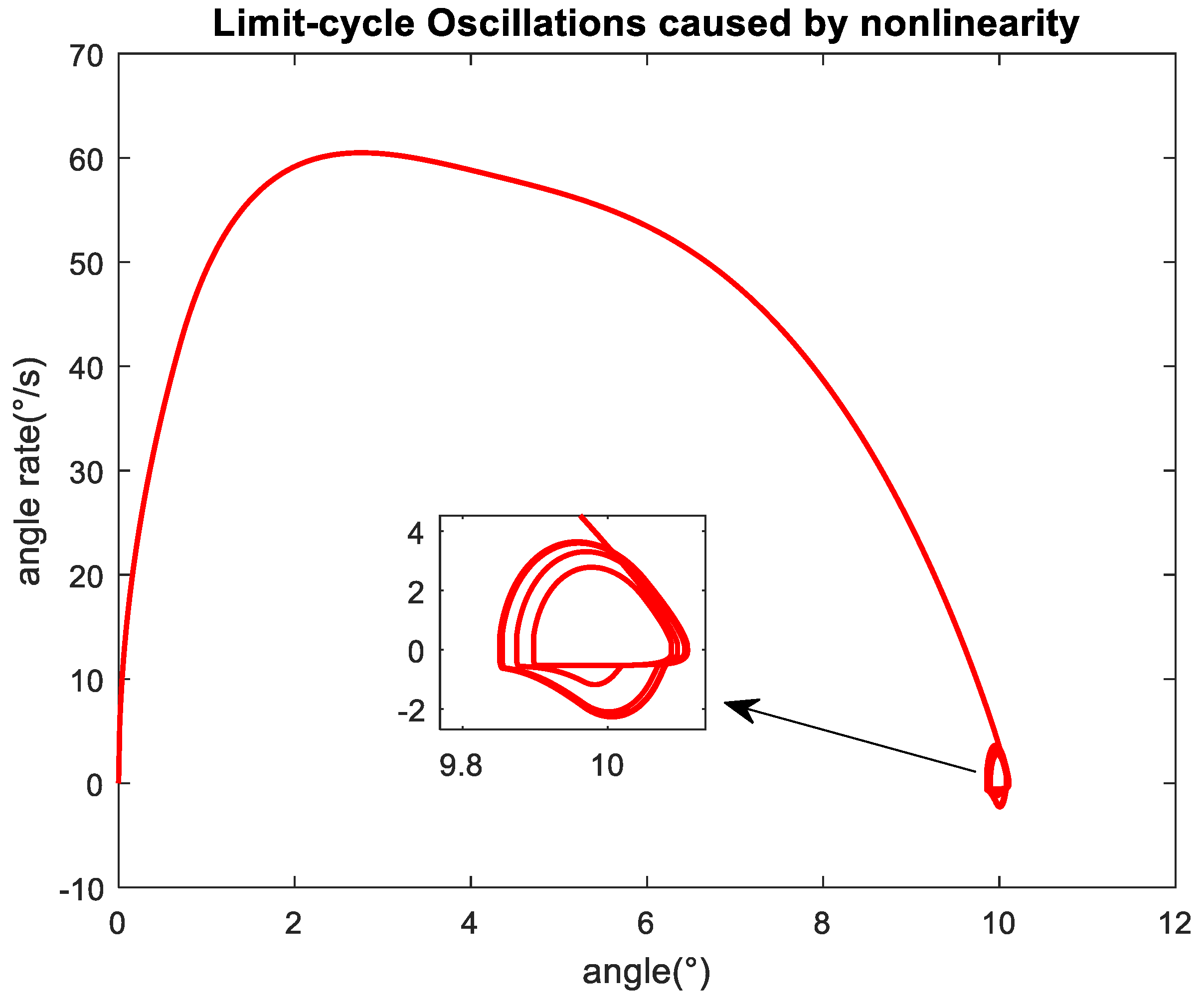
Figure 4 shows that under PID control, when the dead-zone is small, the output deflection angle of the actuator can quickly track the command value and the overshoot is small. However, with the dead-zone widening, the adjustment time becomes longer and the overshoot gradually increases. When the dead-zone is 4 V, the system enters into the limit ring oscillation state. When analyzing it with a description function, it can be seen that the system enters a critical steady state. The phase locus of the limit cycle can be observed through the phase plane in
Figure 5. It indicates that PID control has a weak ability to suppress the dead-zone non-linearity. When the dead-zone exceeds a certain degree, the system will enter into the oscillation state.
Figure 6 shows that when ADRC control is adopted, the overshoot of dynamic response increases with the increase of dead-zone, but the increment is small, and its dynamic response curve is basically consistent within a large range of dead-zone variation, with good stability and small overshoot.
Figure 7 shows that the state observer can observe the disturbance caused by the non-linear dead-zone within the system, and the estimated value of the disturbance quantity increases with the increase of the dead-zone.
Comparing the two control methods, when the load is fixed, the dead-zone non-linearity has a greater impact on the stability of the system under PID control, and when the dead-zone is large, limit cycle oscillation will occur. The ADRC control is less affected by the dead-zone, and the performance is better than PID control.
2.3.2. Load Disturbance Affects
In the setting of demand deflection angle at 10°, dead-zone voltage is set to 3 V, and the load is set to 2 N·m, 10 N·m, 20 N·m, and 30 N·m, respectively, and the dynamic responses under PID and ADRC are shown in
Figure 8,
Figure 9,
Figure 10 and
Figure 11.
As seen from
Figure 8, where there is a dead-zone of 3 V and the load is 2 N·m, the system controlled by PID enters the limit cycle oscillation state, and the limit cycle oscillation can be observed by the phase locus, as shown in
Figure 9. By increasing load, the overshoot gradually decreases (the decrement is small), and the output quickly stabilizes to the set value. It can be seen that when the voltage dead-zone is certain, PID control performance is significant within the rated load range. However, at light load, due to the non-linearity of the dead-zone, the system enters the critical stable region and the limit cycle oscillation occurs.
As shown in
Figure 10, the overshoot of the ADRC hardly increases with the load increases, and the control output quickly reaches the set value. At light loads, the system’s responses slightly slower but have no oscillation.
Figure 11 shows the disturbances estimated by ESO under different loads, and the value increases as the load rises. The comparison shows that under the condition of load changes, ADRC control and PID control have better control effects except for light load. At light loads, the ADRC control is better than the PID control.
2.3.3. Command Angle Affects
Set the dead-zone voltage to 3 V, and the load to 15 N·m, when the step setting angle is 2°, 6°, 15°, the responses simulated under PID control and ADRC at different setting angles. The curves are shown in
Figure 12,
Figure 13,
Figure 14 and
Figure 15.
It can be seen from the results that under different angles, the PID controller has a faster response when the set deflection angle is small, but the overshoot is large and the adjustment time is long. As the set angle increases, the system response time becomes longer and the overshoot is gradually reduced. The ADRC controller has an excellent control effect at different command values, and the response times are basically the same. As can be seen from
Figure 15, the ESO can estimate the total disturbance of the system in different angle commands. The input command values are the largest source of external disturbance for the system.
Based on the above analysis, the dead-zone non-linearity has a great influence on the control performance of the actuator. ADRC can compensate the dead-zone non-linearity in a large range, and when the load disturbance and the command value vary within a wide range, it still has better control effects. However, when the PID control is applied, as the dead-zone changes and the external set value changes widely, the control robustness is poor. When the load is small, the limit cycle oscillation will occur, so the existence of non-linear dynamic characteristics of actuators may destroy the stability of the attitude control system. Therefore, in the following missile attitude control, actuator as the inner closed loop, ADRC is adopted to suppress the influence of dead-zone non-linearity on the performance of the actuator.
3. Modeling and Analysis of Attitude Control of Missile
In this section, pitch attitude control with wind disturbance during the ascent phase of pitchaxis is considered for a missile. The ADRC scheme is proposed to attitude control close loop system. The model integrated with the actuator close-loop under wind disturbance is constructed and simplified for ADRC, and related simulations are given.
3.1. Pitch Control Model Considering Wind Disturbance
The model of the missile in this paper has an axis-symmetric and cruciform shape, based on the general assumption [
26], the model in the ascent phase that considers gust disturbances is shown in
Figure 16.
Assuming that the missile is not disturbed by the wind at the initial state, by this time, the flight state of the rocket is: the ground speed is
, the angle of attack is
, the track angle is
, the pitch angle is
, and the roll angle is
. Then assume wind
act on the missile in the direction as shown in
Figure 16, so that the wind deflects the missile by
with respect to the direction of air velocity. That is, the increment of the angle of attack under wind disturbance is defined as
. At this time, the angle of attack changed into
, for the sake of research, wind speed can be decomposed into vertical speed
and horizontal speed
, consider
as air speed, then
,
and
fulfill the relationship
.
In this paper, the wind is considered to be vertical wind, and at this point, the vehicle will generate an additional angle of attack [
27].
As in
Figure 16,
refers to the longitudinal plane of the ground coordinate system, and
to the axis of the center of the projectile body,
is the thrust of the rocket engine,
is the resistance, Y is lift and
is gravity.
As reference [
28], make the wind a disturbance factor, and the non-linear mathematical model of the missile pitching channel under the vertical wind disturbance is obtained as follows
, , are the moments of inertia of roll, yaw and pitch axes.
3.2. Design of ADRC Attitude Controller
Based on Equations (22)–(27), in order to construct a model that is suitable for ADRC, it is necessary to transform the non-linear dynamic model. Deriving (23), substituting (24) into (23), and considering
, the model can be given by
where
,
,
,
,
are the corresponding torque coefficients generated by corresponding parameter unit changes respectively.
Equation (28) can be rewritten as
where
,
Take the input regulation parameter
, and take the term that does not obviously contain
as the total disturbance
, (29) can be reduced to
where
For the model (30), take as the extended state variable, and design the ESO according to Equations (11)–(13). Take the observer bandwidth and the observation parameters of the third-order state observer as , then the expansion state is the estimated value of the total disturbance .
Following the method of (14)–(18), take the PD controller and make a reasonable selection of the controller frequency and damping ratio, where
,
are the parameters of the controller, the values are related to the natural oscillation frequency
and the damping coefficient
of the rocket. Under the action of wind, consider the non-linearity of the dead-zone of the actuator. The simulation block diagram is shown in
Figure 17.
In the figure, is the pitch angle given value and is the wind, which is considered as the external disturbance of the non-linear model.
In order to compare with the traditional controller, a PID gain scheduling controller is designed. The control parameters of the method are predesigned under little disturbance theory at the selected different characteristic points thought the flight trajectory, and the control parameters cannot be changed according to large external disturbances in real-time. So, when encountering relatively large wind disturbances, the system will have greater parameter uncertainty, and the system may be out of control.
3.3. Simulation and Analysis
In this part, the simulation analysis combined with actuator dynamics and attitude control of the pitch channel is carried out. The parameters of the actuator refer to
Table 1. Basic data of the missile can be seen in
Table 2.
In the simulation process, dynamic characteristics of the steering gear and vertical interfering wind factors are taken into account. The relevant parameters of ADRC control of the pitch channel are
As the contrast controller, the angular rate feedback coefficient, proportionality coefficients, integral coefficients and differential coefficients of PID are pre-calculated by the linear model at the characteristic points, and the global controller is obtained by fitting the linear controller parameters at all characteristic points by interpolation.
According to the discussion in
Section 2, for the non-linear actuator, the PID control effect is not satisfactory, which may have a great impact on attitude control. Therefore, this paper considers an actuator with a dead-zone voltage of 3 V and adopts ADRC control. The control parameters are still:
,
,
. That is, take the equivalent damping ratio is 1, the corresponding parameters are
= 113 and
= 3192.25.
In order to illustrate the problem in this paper, without considering the structural strength and overload capacity of the missile, different vertical wind speeds (the wind speeds are set to be 15 m/s, 20 m/s, 25 m/s, 30 m/s and 35 m/s respectively, they are represented by wind-1, wind-2 wind-3, wind-4 and win-5, respectively, in the figures) are added in the model during the ascent phase when t = 4–8 s. The ADRC and PID controller responses of pitch control are presented, respectively. Simulation results are shown in
Figure 18,
Figure 19,
Figure 20,
Figure 21,
Figure 22 and
Figure 23.
Figure 18 and
Figure 19 show the pitch angle response curves under ADRC and PID control respectively. It can be known that under ADRC control, under a wide range of wind disturbances, the maximum fluctuation of pitch angle is only 0.8°, and it reaches the command value after a recovery time of about 1.5 s. However, under PID control, the maximum fluctuation reaches up to 11.3°, and the pitch angle changes dramatically, the control overshoot is large, and the recovery time is near 5 s.
Figure 20 and
Figure 21 show the output deflection angles of the actuator loop when the pitch attitude is controlled by ADRC and PID, respectively, under different wind strengths. Figures show that under the control of ADRC, the influence of the disturbance on the actuator is limited, the deflection range of the actuator is small, and the actions are steady. However, under the PID control, the deflection angle of the actuator is up to 6° due to the high wind, and the deflection angle is large. Correspondingly, as seen in
Figure 22 and
Figure 23, the torque responses between the two control methods in the pitch channel are huge. Under the PID with high wind, the pitching torque varies up to 12 KN. In this case, the rocket is subjected to a large overload, and this is a significant challenge to the structural strength of the rocket. Under the control of ADRC, wind disturbance can be resisted and a good tracking effect is realized.
4. Conclusions
To compensate for the effect of non-linear dynamics on the actuator and suppress the influence of un-modeled dynamics and wind disturbance on missile during the ascent phase, and for the non-linear actuator with dead-zone, a control model suitable for the ADRC control method was constructed. Meanwhile, a model suitable for the ADRC control framework was constructed for the pitching plane of the missile considering wind disturbance. Later, the cascade ADRC control structure was constructed by combining the internal loop of the actuator and the external loop of pitch attitude control. The ADRC controllers, contrasted with PID controllers were designed separately.
Simulation results show that accurate modeling is not necessary under ADRC control. For actuator close loop with voltage dead-zone, the presence of non-linearity under certain conditions causes the actuator to generate limit cycle oscillations. Meanwhile, the dynamic response varies greatly when the system is operating at different loads and different command angles, which can generate a serious impact on missile attitude control. Dead-zone non-linearity, model uncertainty and external disturbances can all be estimated and compensated for under ADRC control. The controller has excellent control performance and robustness under different dead-zones, different command angles, and rated load ranges.
The vertical wind has a great influence on the attitude control of the pitch channel during the ascent phase. Under the traditional PID gain scheduling control, the pitching moment changes drastically, which will cause structural damage, and it is difficult to apply to suppress strong gusts. ADRC can estimate and suppress the external gust disturbance properly, and it has a very good capability in tracking attitude command; as a consequence, ADRC has stronger robustness and stability than PID.


