Experimental Investigation of the Flow Mechanisms and the Performance Change of a Highly Loaded Axial Compressor Stage with/without Stator Hub Clearance


Abstract
:1. Introduction
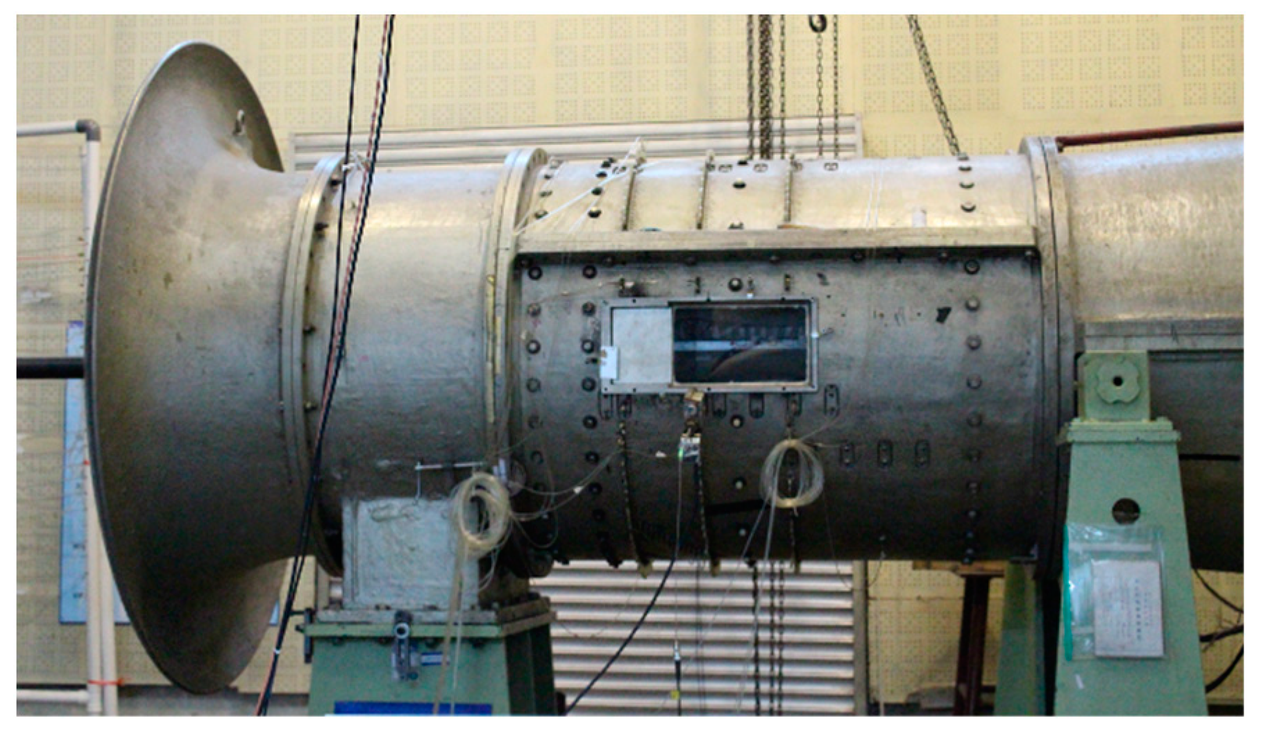
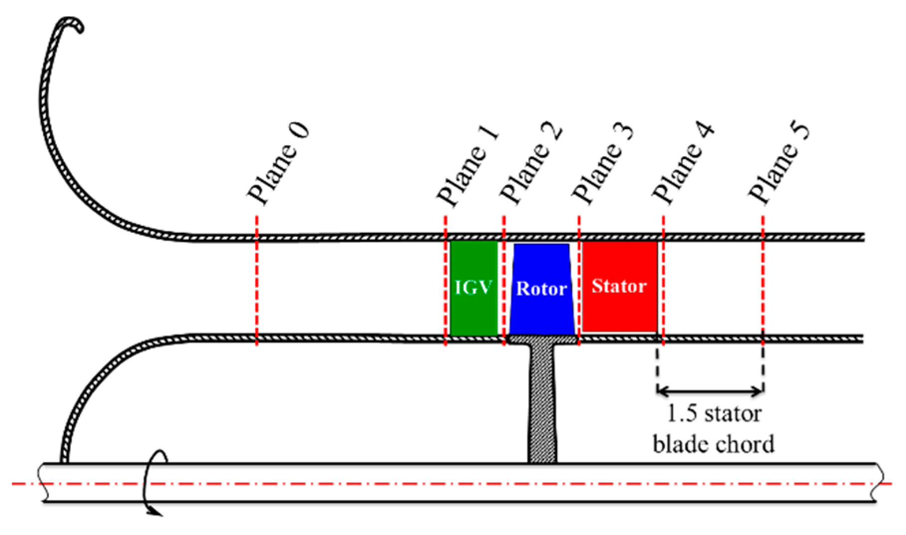
2. Experiment Setup
3. Results
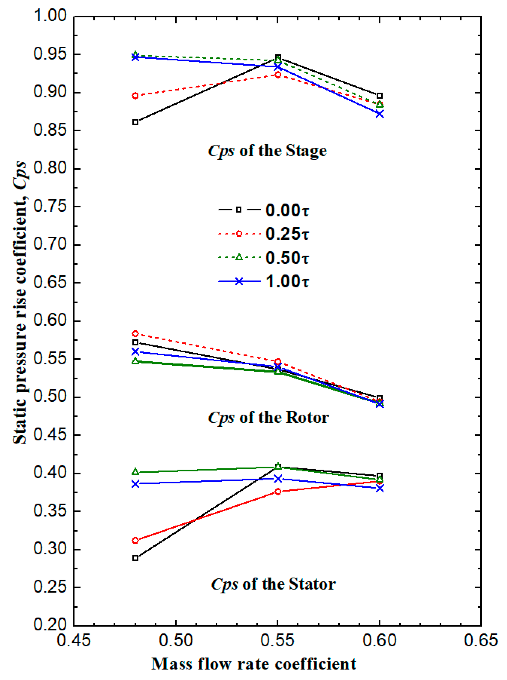
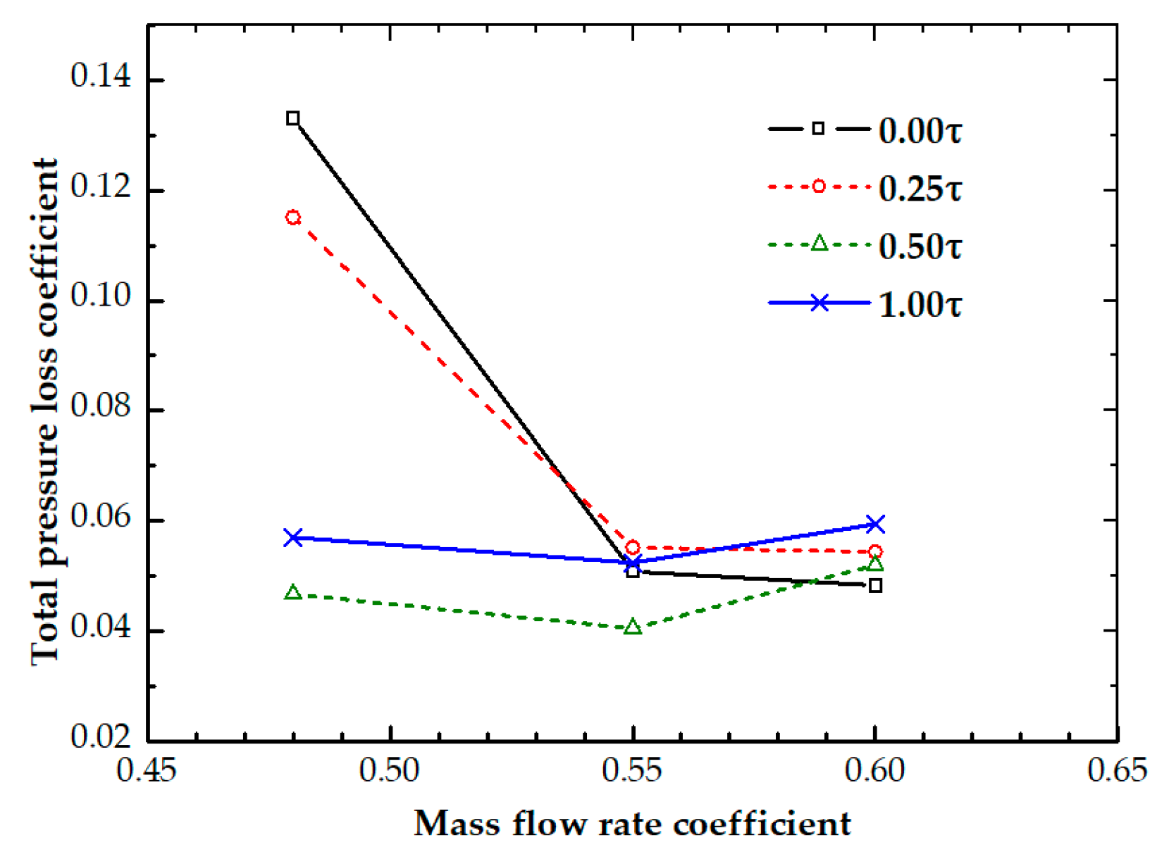
3.1. Overall Characteristics of the Compressor
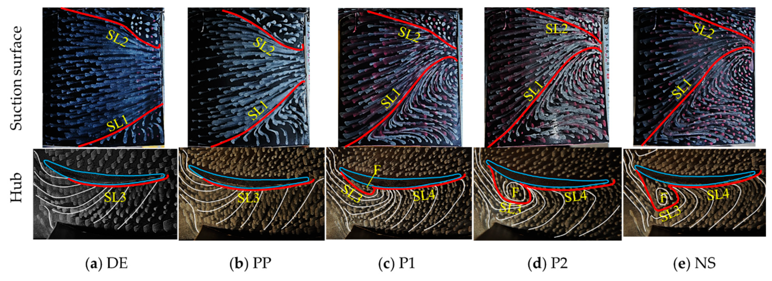
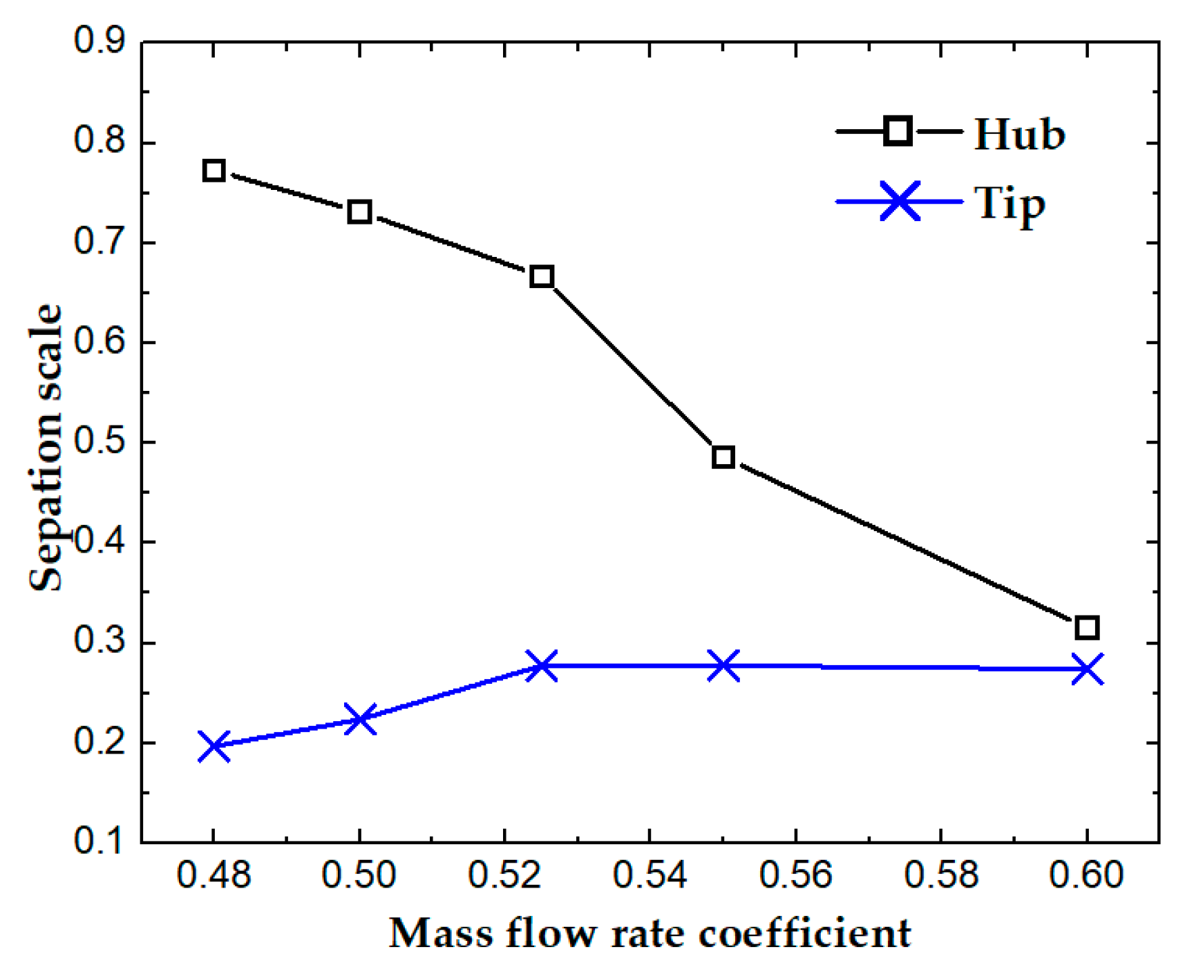
3.2. The Evolution of Stator Corner Separation at Zero Clearance
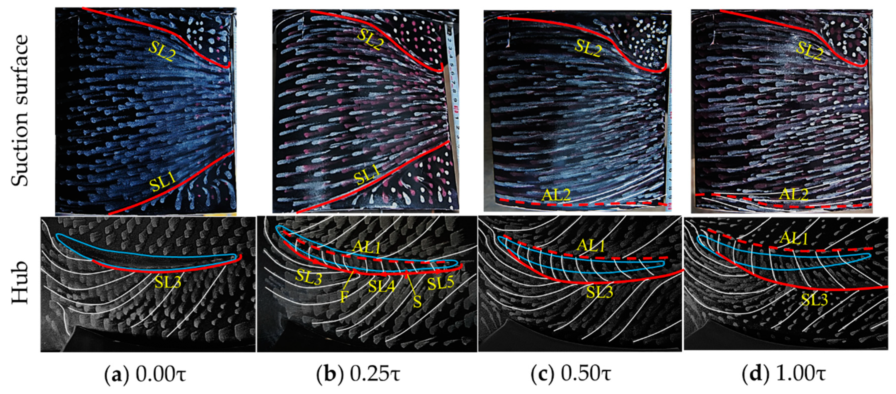
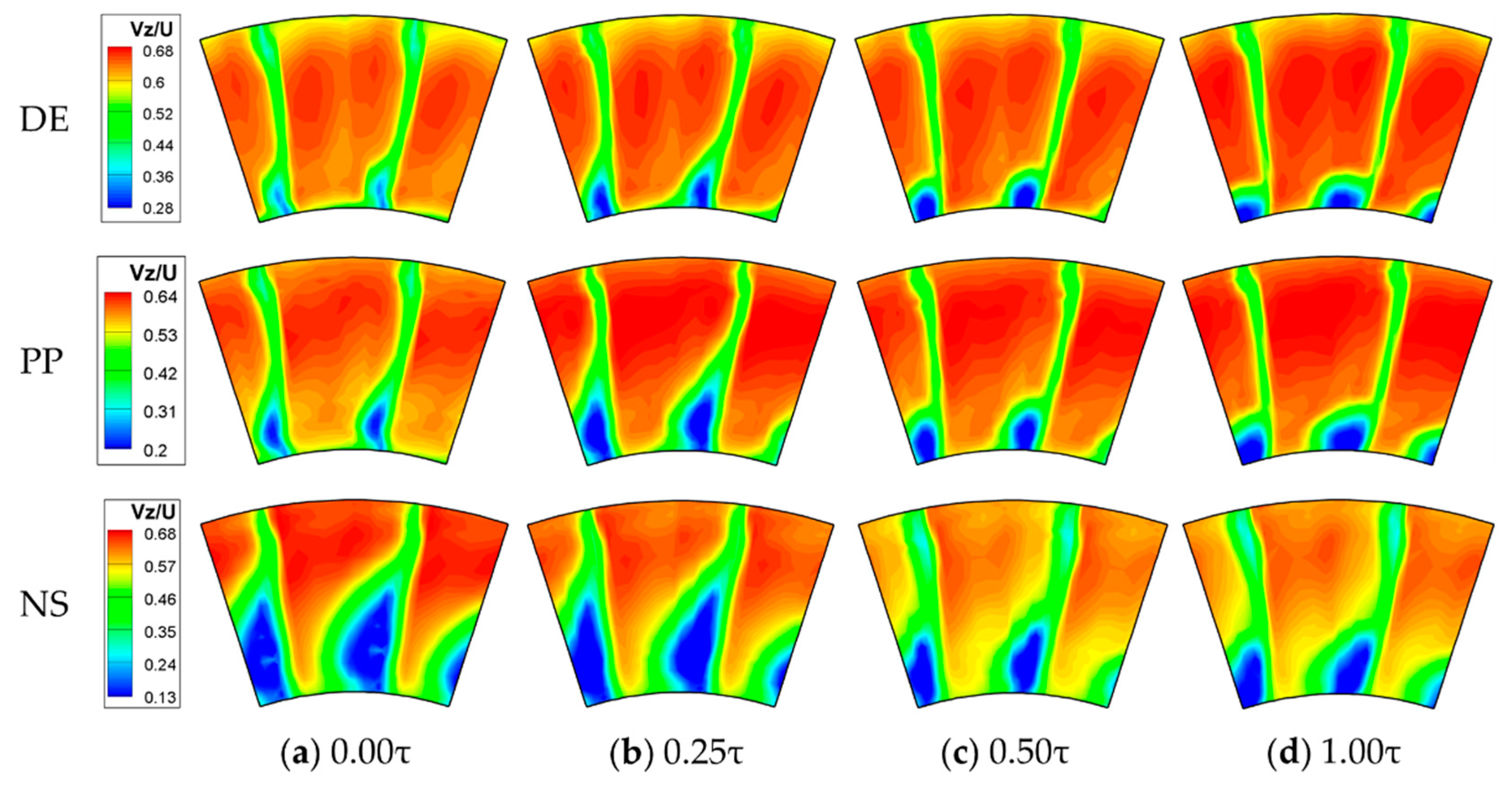
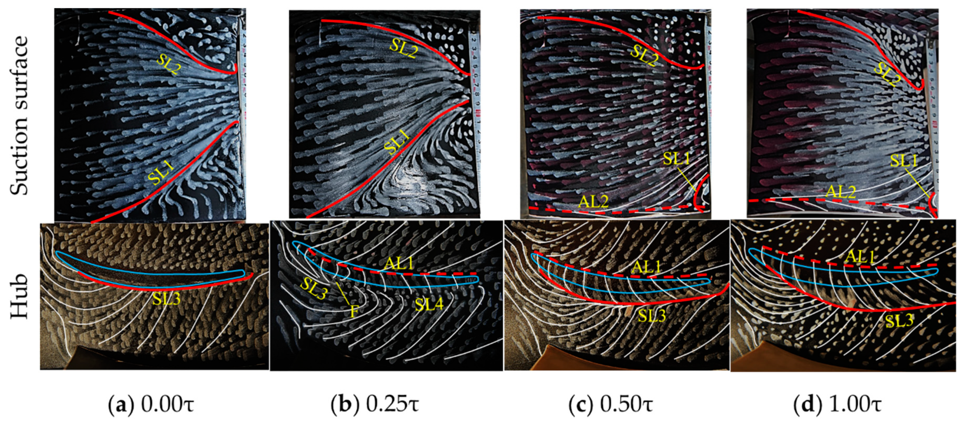
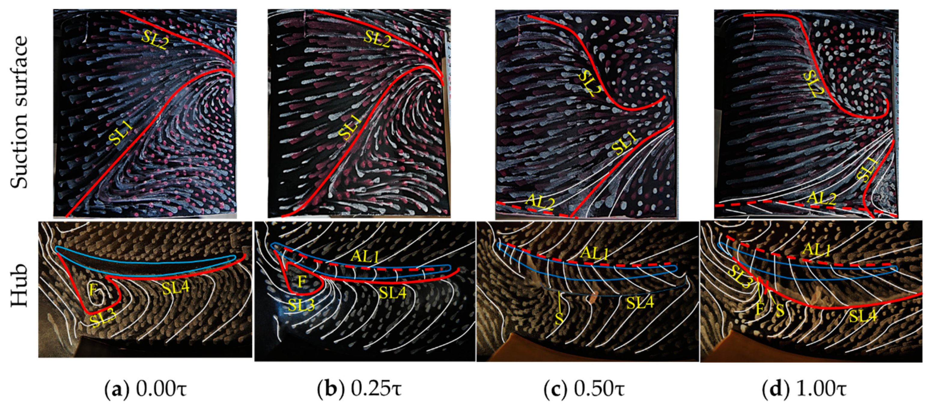
3.3. Influence of the Size of Stator Hub Clearance on the Evolution of Flow Topologies
3.3.1. Results at the DE Condition
3.3.2. Results at the PP Condition
3.3.3. Results at the NS Condition
3.4. Typical Flow Structures in the Stator Hub Corner
4. Discussion
4.1. Source of the Variation of the Compressor Performance
4.2. Effect of Stator Hub Clearances on the Stator Performance
5. Conclusions
- (1)
- At zero clearance, hub corner separation turns into a corner stall as long as the stator incidence is larger than the critical incidence, which makes the compressor performance drop rapidly.
- (2)
- At large mass flow rate conditions (before the occurrence of the hub corner stall), the introduction of a very small stator hub clearance (0.25% blade height here) will not improve the hub corner flow, on the contrary, it makes the corner separation more severe and prompts the occurrence of corner stall, which is mainly caused by the fact that the leakage flow has relatively low energy due to the viscosity effect in the clearance and large flow loss generation as the clearance flow comes across and mixes with the transverse secondary flow; when the stator hub clearance increases, the enhanced leakage flow can suppress the transverse migration of the low energy flow near the hub, but excessive leakage flow could induce new mixing loss.
- (3)
- At small mass flow rate conditions (when the corner stall occurs), the hub clearance flow can also suppress the low energy flow to roll into the recirculation region around focus point at the downstream of leading edge on the hub, hence, the strength of the corner stall is diminished even at the very small clearance, and the hub corner stall is eliminated when the hub clearance increases to 0.5% blade height or bigger.
- (4)
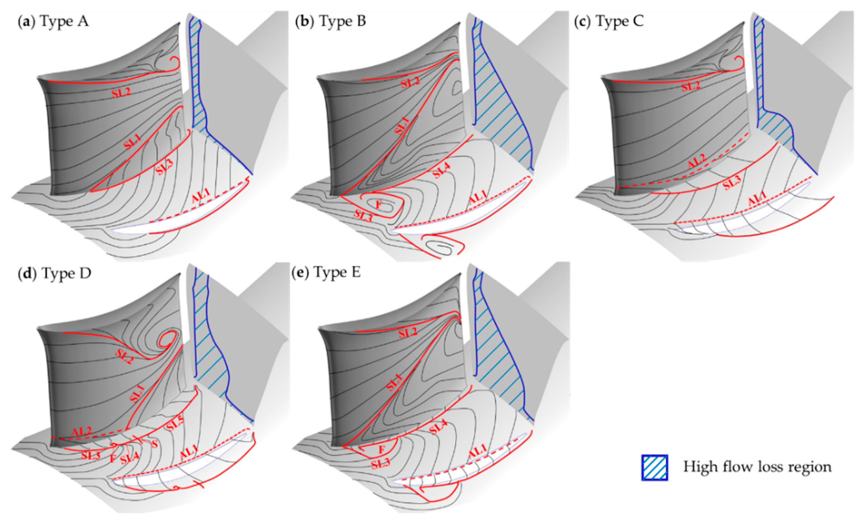
- As the stator hub clearance varies, there are five typical flow structures in the stator hub corner, namely, Type A, Type B, Type C, Type D and Type E. Type A and Type B correspond to the traditional hub corner separation and corner stall, Type C corresponds to the traditional hub clearance flow, Type D corresponds to the coexistence of the hub leakage flow and the corner separation, and Type E corresponds to the coexistence of the hub leakage flow and the corner stall.
- (5)
- The evolution of the flow topologies inside the stator passage along with the variation of stator hub clearance has an obvious influence on the performance of the compressor, and the flow mechanisms of the effect of the stator hub clearance on the compressor performance is discussed in detail. It is found that there exists an optimum stator hub clearance makes the flow inside the stator to be the most rational and the compressor performance to be the best.
Author Contributions
Funding
Conflicts of Interest
Abbreviations
| Cps | Static pressure rise coefficient |
| Cpt | Total pressure coefficient |
| Cvz | Normalized axial velocity, Vz / Um |
| Loss | Total pressure loss coefficient |
| Re | Reynolds number |
| r | Radial position |
| s | Circumferential position |
| t | Blade pitch |
| Um | Rotor speed at middle span |
| Vz | Axial velocity |
| φ | Mass flow coefficient |
| Ratio of the clearance size to the maximum thickness of the blade airfoil | |
| Ratio of blade maximum thickness to the blade chord | |
| Flow density | |
| Blade wake width in pitchwise |
References
- Lei, V.M.; Spakovszky, Z.; Greitzer, E. A Criterion for Axial Compressor Hub-Corner Stall. J. Turbomach. 2008, 130, 031006. [Google Scholar] [CrossRef]
- Taylor, J.V.; Miller, R.J. Competing Three-Dimensional Mechanisms in Compressor Flows. J. Turbomach. 2016, 139, 021009. [Google Scholar] [CrossRef]
- Joslyn, D.; Dring, R. Axial Compressor Stator Aerodynamics. J. Eng. Gas Turbines Power 1985, 107, 485–492. [Google Scholar] [CrossRef]
- Schulz, H.; Gallus, H. Experimental investigation of the three-dimensional flow in an annular compressor cascade. J. Turbomach. 1988, 110, 467–478. [Google Scholar] [CrossRef]
- Sachdeva, A. Study and Control of Three Dimensional flow Separations in a High Pressure Compressor Stator Blade Row by Boundary Layer Aspiration. Ph.D. Thesis, Ecole Centrale de Lyon, Écully, France, 21 June 2010. [Google Scholar]
- Ma, S.; Chu, W.; Zhang, H.; Li, X.; Kuang, H. A combined application of micro-vortex generator and boundary layer suction in a high-load compressor cascade. Chin. J. Aeronaut. 2019, 32, 1171–1183. [Google Scholar] [CrossRef]
- Gbadebo, S.A.; Cumpsty, N.A.; Hynes, T.P. Control of three-dimensional separations in axial compressors by tailored boundary layer suction. J. Turbomach. 2008, 130, 011004. [Google Scholar] [CrossRef]
- Peacock, R. Boundary-Layer Suction to Eliminate Corner Separation in Cascades of Aerofoils; Citeseer: London, UK, 1965. [Google Scholar]
- Kirtley, K.R.; Graziosi, P.; Wood, P.; Beacher, B.; Shin, H.-W. Design and Test of an Ultra-Low Solidity Flow-Controlled Compressor Stator. In Proceedings of the ASME Turbo Expo 2004: Power for Land, Sea, and Air, Vienna, Austria, 14–17 June 2004; pp. 297–308. [Google Scholar]
- Song, Y.; Chen, H.; Chen, F.; Wang, Z. Effects of Air Injection on Performance of Highly-Loaded Compressor Cascades. In Proceedings of the ASME Turbo Expo 2007: Power for Land, Sea, and Air, Montreal, QC, Canada, 14–17 May 2007; pp. 77–86. [Google Scholar]
- Nerger, D.; Saathoff, H.; Radespiel, R.; Gümmer, V.; Clemen, C. Experimental investigation of endwall and suction side blowing in a highly loaded compressor stator cascade. J. Turbomach. 2012, 134, 021010. [Google Scholar] [CrossRef]
- Hergt, A.; Meyer, R.; Engel, K. Experimental Investigation of Flow Control in Compressor Cascades. In Proceedings of the ASME Turbo Expo 2006: Power for Land, Sea, and Air, Barcelona, Spain, 8–11 May 2006; pp. 231–240. [Google Scholar]
- Breugelmans, F.; Carels, Y.; Demuth, M. Influence of dihedral on the secondary flow in a two-dimensional compressor cascade. J. Eng. Gas Turbines Power 1984, 106, 578–584. [Google Scholar] [CrossRef]
- Weingold, H.D.; Neubert, R.J.; Behlke, R.F.; Potter, G.E. Reduction of compressor stator endwall losses through the use of bowed stators. In Proceedings of the ASME 1995 International Gas Turbine and Aeroengine Congress and Exposition, Houston, TX, USA, 5–8 June 1995. [Google Scholar]
- Dean, R.C. Secondary Flow in Axial Compressors. Ph.D. Thesis, Massachusetts Institute of Technology, Cambridge, MA, USA, 17 May 1954. [Google Scholar]
- Lakshminarayana, B. Methods of predicting the tip clearance effects in axial flow turbomachinery. J. Basic Eng. 1970, 92, 467–480. [Google Scholar] [CrossRef]
- Lakshminarayana, B.; Horlock, J. Tip-Clearance Flow and Losses for an Isolated Compressor Blade; Aeronautical Research Council London (England): London, UK, 1963. [Google Scholar]
- Lakshminarayana, B.; Horlock, J. Leakage and Secondary Flows in Compressor Cascades; HM Stationery Office: Richmond, UK, 1967. [Google Scholar]
- Singh, U.K.; Ginder, R.B. The Effect of Hub Leakage Flow in a Transonic Compressor Stator. In Proceedings of the ASME 1998 International Gas Turbine and Aeroengine Congress and Exhibition, Stockholm, Sweden, 2–5 June 1998. [Google Scholar]
- Lee, C.; Song, J.; Lee, S.; Hong, D. Effect of a gap between inner casing and stator blade on axial compressor performance. In Proceedings of the ASME Turbo Expo 2010: Power for Land, Sea, and Air, Glasgow, UK, 14–18 June 2010; pp. 203–210. [Google Scholar]
- George, K.K.; Sunkara, S.N.A.; George, J.T.; Joseph, M.; Pradeep, A.; Roy, B. Investigations on stator hub end losses and its control in an axial flow compressor. In Proceedings of the ASME turbo expo 2014: Turbine technical conference and exposition, Düsseldorf, Germany, 16–20 June 2014. [Google Scholar]
- Gbadebo, S.A.; Cumpsty, N.A.; Hynes, T.P. Interaction of tip clearance flow and three-dimensional separations in axial compressors. J. Turbomach. 2007, 129, 679–685. [Google Scholar] [CrossRef]
- Dong, Y.; Gallimore, S.; Hodson, H. Three-dimensional flows and loss reduction in axial compressors. J. Turbomach. 1987, 109, 354–361. [Google Scholar] [CrossRef]
- Peacock, R. A review of turbomachinery tip gap effects: Part 1: Cascades. Int. J. Heat Fluid Flow 1982, 3, 185–193. [Google Scholar] [CrossRef]
- Sakulkaew, S.; Tan, C.; Donahoo, E.; Cornelius, C.; Montgomery, M. Compressor efficiency variation with rotor tip gap from vanishing to large clearance. J. Turbomach. 2013, 135, 031030. [Google Scholar] [CrossRef]
- Wennerstrom, A. Experimental study of a high-throughflow transonic axial compressor stage. J. Eng. Gas Turbines Power 1984, 106, 552–560. [Google Scholar] [CrossRef]
- McDougall, N. A comparison between the design point and near-stall performance of an axial compressor. J. Turbomach. 1990, 112, 109–115. [Google Scholar] [CrossRef]
- Liu, B.J.; An, G.F.; Yu, X.J.; Zhang, Z.B. Experimental investigation of the effect of rotor tip gaps on 3D separating flows inside the stator of a highly loaded compressor stage. Exp. Therm. Fluid Sci. 2016, 75, 96–107. [Google Scholar] [CrossRef]
- Liu, B.J.; Zhang, S.; Yu, X.J. Experimental investigations on the effects of bowed stator in a highly loaded axial compressor stage. In Proceedings of the 2014 ISFMFE—6th International Symposium on Fluid Machinery and Fluid Engineering, Wuhan, China, 22–25 October 2014. [Google Scholar]
- Yu, X.J.; Liu, B.J. Research on three-dimensional blade designs in an ultra-highly loaded low-speed axial compressor stage: Design and numerical investigations. Adv. Mech. Eng. 2016, 8. [Google Scholar] [CrossRef]
- Liu, B.J.; An, G.F.; Yu, X.J. Assessment of curvature correction and reattachment modification into the shear stress transport model within the subsonic axial compressor simulations. Proc. Inst. Mech. Eng. Part A J. Power Energy 2015, 229, 910–927. [Google Scholar] [CrossRef]
- Everett, K.N.; Gerner, A.A.; Durston, D.A. Seven-hole cone probes for high angle flow measurement Theory and calibration. AIAA J. 1983, 21, 992–998. [Google Scholar] [CrossRef]
- Rains, D.A. Tip Clearance Flows in Axial Compressors and Pumps. Ph.D. Thesis, California Institute of Technology, Pasadena, CA, USA, 1954. [Google Scholar]
- Zhang, S. Study on the Mechanism of the 3D Blade Design of Highly Loaded Subsonic Axial Compressor. Ph.D. Thesis, Beihang University, Beijing, China, 29 June 2018. [Google Scholar]
- Gbadebo, S.A.; Cumpsty, N.A.; Hynes, T.P. Three-Dimensional Separations in Axial Compressors. J. Turbomach. 2005, 127, 331–339. [Google Scholar] [CrossRef]


| Outer diameter (mm) | 1000 |
| Hub-to-tip ratio | 0.6 |
| Number of blades | 36 (IGV); 17(rotor); 20 (stator) |
| Blade camber angle (°) | 7(IGV); 34.3(rotor); 45.3 (stator) |
| Blade stagger angle (°) | 5(IGV); 37.7(rotor); 18.1 (stator) |
| Blade nominal height (mm) | 200(IGV); 200 (rotor); 200 (stator) |
| Blade chord (mm) | 95(IGV); 172(rotor); 183(stator) |
| Rotor tip nominal clearance (mm) | 2.0 |
| Stator tip nominal clearance (mm) | 0.0/0.5/1.0/2.0 |
| Conditions | DE (φ = 0.6) | PP (φ = 0.55) | P1 (φ = 0.525) | P2 (φ = 0.5) | NS (φ = 0.48) | |
|---|---|---|---|---|---|---|
| Clearance | ||||||
| 0.00τ | 5h and Oil 1 | 5h and Oil | Oil | Oil | 5h and Oil | |
| 0.25τ | 5h and Oil | 5h and Oil | - | - | 5h and Oil | |
| 0.50τ | 5h and Oil | 5h and Oil | - | - | 5h and Oil | |
| 1.00τ | 5h and Oil | 5h and Oil | - | - | 5h and Oil | |
© 2019 by the authors. Licensee MDPI, Basel, Switzerland. This article is an open access article distributed under the terms and conditions of the Creative Commons Attribution (CC BY) license (http://creativecommons.org/licenses/by/4.0/).
Share and Cite
Liu, B.; Qiu, Y.; An, G.; Yu, X. Experimental Investigation of the Flow Mechanisms and the Performance Change of a Highly Loaded Axial Compressor Stage with/without Stator Hub Clearance. Appl. Sci. 2019, 9, 5134. https://doi.org/10.3390/app9235134
Liu B, Qiu Y, An G, Yu X. Experimental Investigation of the Flow Mechanisms and the Performance Change of a Highly Loaded Axial Compressor Stage with/without Stator Hub Clearance. Applied Sciences. 2019; 9(23):5134. https://doi.org/10.3390/app9235134
Chicago/Turabian StyleLiu, Baojie, Ying Qiu, Guangfeng An, and Xianjun Yu. 2019. "Experimental Investigation of the Flow Mechanisms and the Performance Change of a Highly Loaded Axial Compressor Stage with/without Stator Hub Clearance" Applied Sciences 9, no. 23: 5134. https://doi.org/10.3390/app9235134
APA StyleLiu, B., Qiu, Y., An, G., & Yu, X. (2019). Experimental Investigation of the Flow Mechanisms and the Performance Change of a Highly Loaded Axial Compressor Stage with/without Stator Hub Clearance. Applied Sciences, 9(23), 5134. https://doi.org/10.3390/app9235134