1. Introduction
Inductance calculation is one of the most basic problems in inductor design. The most accurate method is to use the electromagnetic finite element method (FEM) [
1], which requires a geometry model and a long calculation time so that it cannot be calculated online in real-time [
2,
3,
4]. Another method is to use the magnetic equivalent circuit (MEC) model which has the advantages of fast calculation speed and acceptable accuracy. At present, the MEC model can be used to accurately calculate the inductance of the operating point below the saturation point. However, the inductance of multiple operating points or the full current range cannot be well predicted, especially when the core is saturated.
The main factor affecting the calculation accuracy of the MEC model is whether the reluctance calculation of each part is correct. Recently, for the power inductor, some researchers focused on the model of the air gap [
5,
6], and leakage flux reluctance such as leakage flux of the core window [
7] and fringing leakage [
8]. Some researchers are concerned about the MEC model’s net forms of different types of inductor. Liu [
9] establishes a MEC model of the Y-shape, △-shape to design an inductor by the magnetic integration method. Duppalli [
10] and Cale [
11] established a standard UI-shape (where an “UI-shape” core is composed of an U-shaped core and an I-shaped core) and EI-shape (where an “EI-shape” core is composed of an E-shaped core and an I-shaped core) MEC model. These models make great contributions to improving reluctance accuracy.
On the other hand, a few institutions and individuals aimed at the main reluctance of the core, especially the corner. Except for the equivalent corner reluctance model established by the finite element method [
12], the common method is to simplify the corner as a quarter-circle that has a fixed radius, replacing the original rectangular geometry, such as the IEC (International Electrotechnical Commission) 60205 [
13] model, which has a radius equal to half the average length of the corners and is adopted in [
9]. In the Snelling [
14,
15] model, the authors choose a quarter of the average length of the corner as the radius and this corner model is adopted in [
5,
6]. In the Sudhoff [
16] model, the corner flux path length is equal to half the rectangular side beside the limb and is adopted in [
11]. However, these corner models use a single fixed flux path length to calculate the reluctance without considering the nonlinearity of reluctance.
In real cases, the corner flux density distribution is non-uniform where the inner corner is high, and the outer corner flux density is low [
17]. The magnetic flux mainly flows around the inner corner. As the strength of the magnetic field increases, the inner corner reaches saturation and leads to a significant increase in local reluctance and the flux density (
B) distribution also changes. Therefore, the simplified reluctance equivalent length model of the corner is not consistent with the real condition and contributes to inductance error, especially under the saturation condition.
In this paper, we focus on the power inductor, especially with UI/EI or other core structures with rectangular corners. In order to describe the flux density distribution at the corner and improve the accuracy of the core corner reluctance, so as to improve the accuracy of inductance calculation, we propose a local MEC model of a corner. Based on the finite element analysis, the corner and the joint part between the corner and the core limb enclosed by winding are divided into several reluctance branches to describe the flux density distribution. In addition, a reluctance branch describes the leakage flux of how the core window inner corner is modeled, which could contribute to improving the accuracy of the inductance especially when the core is saturated. By the series and parallel combination of the reluctance branches, the flux density distribution of the corner is fully described and accurately calculated, and the inductance can also be accurately calculated.
The rest of this paper organized as follows. In
Section 2, the local MEC model of the corner is established and the corresponding reluctance calculation approach is demonstrated.
Section 3 models the square core-type inductor MEC and gives the methods to calculate the inductance.
Section 4 describes the experiments and analysis, where the core branch flux density
B distribution of the local corner MEC model and FEM simulation are compared. Then, the inductance with the current of the local corner MEC model and IEC model are compared to physical prototype measured results, whereas the relative errors are analyzed. The number of corner branches is also discussed.
Section 4 concludes the study and gives further research points.
2. Modeling and Analysis of Corner
2.1. Geometry of Square Core-Type Inductor
In this paper, a symmetric square core-type inductor is designed, as shown in
Figure 1, which uses Fe-Si power 26
μ [
18] material and contains four blocks of 23 mm × 30 mm × 90 mm in the core. Since the power core material is used, the core does not contain functional air gaps as a steel core inductor, in which the reluctance of the core is the main factor of the inductance. The geometry parameters are shown in
Table 1. In the square inductor, there are four windings, a total of 40 turns, and each winding has 10 turns evenly distributed over four limbs, such that the four core limbs have even and identical flux distribution, and the corner has symmetrical flux distribution. This makes it easy to study the flux density distribution of the corner. In addition, the corners and the joints between the corner and limb account for 40% of the entire core volume, of which reluctance significantly contributes to the inductance calculation. Combined with the above geometric characteristics, the square inductor is a good model for studying the features of the corner.
2.2. Finite Element Analysis of Flux Density Distribution
The electromagnetic finite element analysis of the inductor is carried out to analyze the flux density distribution when the current
i is from 20 A to 1000 A. At 20 A, the average flux density of the core is 0.085 T. At 1000 A, the average flux density of the core is 1.58 T, which has reached the saturation range. The flux density distribution is shown in
Figure 2.
The flux density distribution is symmetric due to the structural symmetry and uniform in the limb enclosed by the winding. In the corner of the core, the flux density is non-uniformly distributed and the non-uniformity increases with current significantly. In the joint part, between the corner and limb surrounded by winding, the flux density distribution of the area near the geometrically symmetric plane is more uniform, and the flux density distribution of the region near the corner is more uneven. In addition, as the excitation is enhanced, the leakage flux of the core window inner corner increases.
Taking into account the characteristics of flux density distribution, in this paper, we propose a local model of these three parts of the core, as shown in
Figure 3, which are corner, the limb joint parts between winding end and corner named Part B and Part C, and the core window inner corner area named Part D. Since the model structure of this paper is symmetrical, Part B and the Part C are identical.
2.3. Modeling of Corner
The flux density distribution of the diagonal line of a corner,
La as shown in
Figure 3, is analyzed and presented in
Figure 4. We can see that the flux density
B in the corner has nonlinear distribution. Specifically, the flux is concentrated around the inner corner because the flux selects a minimum reluctance path, where the reluctance is equal to the ratio of length and the product of permeability and cross-section area [
19]. With the current rising, the flux density increases and the distribution changes because of the nonlinear permeability of the core material.
On the other hand, most of the flux line shape is approximately a circle and the flux density is concentrated in the inner corner. A quarter-circle area is named Part A, in which the radius is the limb width. The energy in Part A and energy in the corner are compared, as shown in
Figure 5.
It can be seen that the ratio of the energy in Part A and the corner is higher than 93% in the range of 20 A to 1000 A, and it slightly decreases as the current increases. Therefore, we chose Part A to replace the corner and use the circle path to study the corner with a negligible error.
Considering the non-uniform flux density
B at the corner, we selected
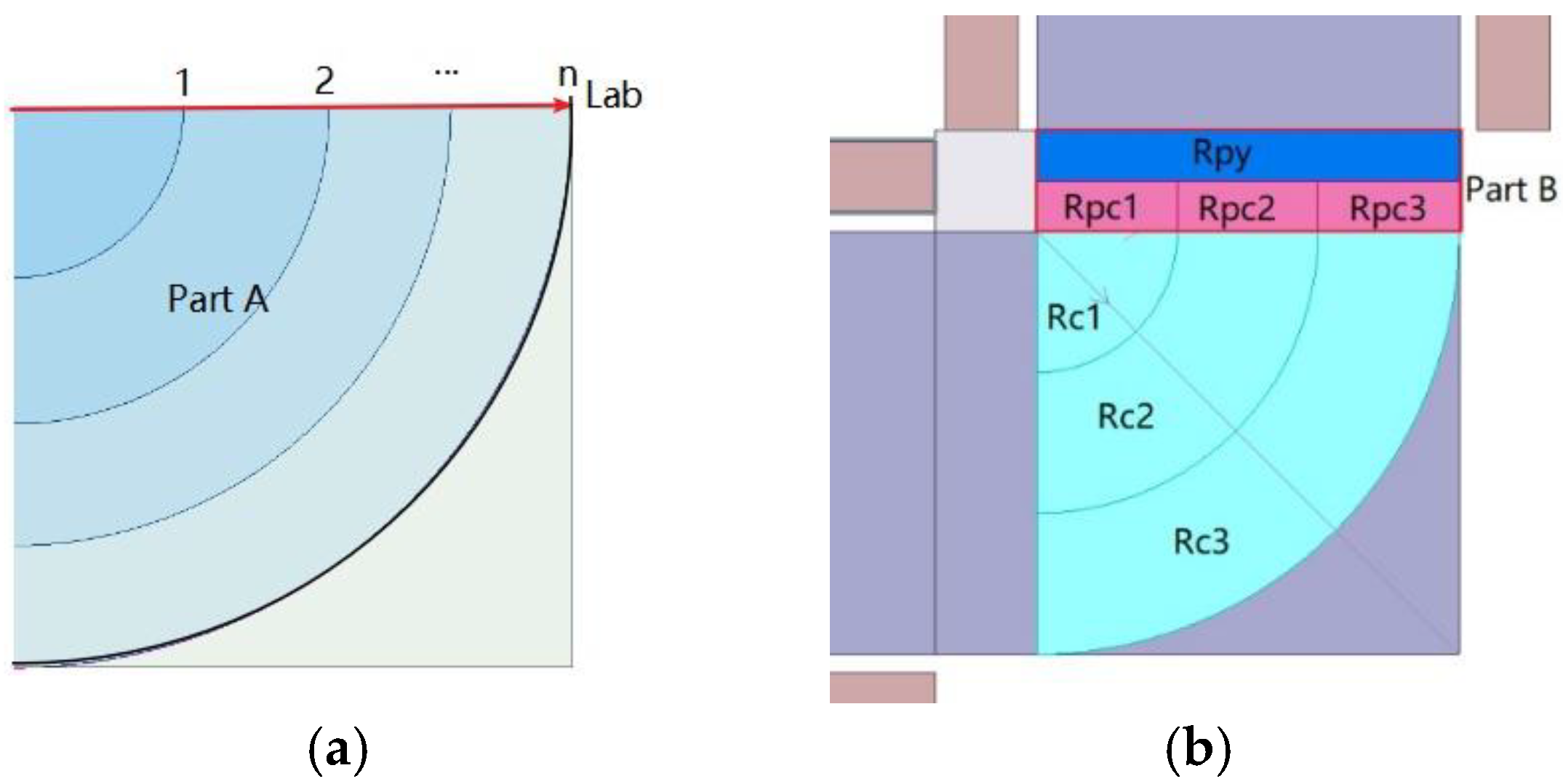
n parallel reluctance branches to replace the traditional single corner reluctance. Here we divide Part A into
n equal divisions along line
Lab and make
n quarter circles by the inner corner and divided points, which divides Part A into
n-1 quarter rings and
1 quarter circle, as shown in
Figure 6a.
The area of each branch Ac,i is expressed in Equation (1).
Taking the middle line of geometry as the length of the magnetic path, the length of the ith magnetic path lc,i is expressed in Equation (2).
Thus the
ith reluctance
Rc,i is calculated in Equation (3).
where
ui(
B) is the
ith branch permeability.
In the corner, the flux density distribution can be accurately reflected with more parallel
Rc,i branches. However, too many parallel flux paths can cause the magnetic equivalent circuit of the corner to be too complicated and affect the convergence of the calculation, especially when the branch is deeply saturated. In this paper, we chose three parallel branches, the inner section, middle section, and the outer section of the corner, which can balance the accuracy of the solution and keep the model simple, as shown in
Figure 6b.
2.4. Modeling of the Limb Joint Part
The distribution of the flux density
B on the line
Lyb at the position of winding end and
Lab at the junction of a corner, shown in
Figure 3, were analyzed and shown in
Figure 7. It can be clearly seen that the flux density distribution limb joint part is similar to the corner, which is high around the inner corner and low near the outer side. On the other hand, the distribution of the limb joint part closed to the winding is uniform, which is similar to the distribution of the limb surrounded by windings. The flux density distribution of line
Lyb is more uniform than the line
Lab, and the ratio of
B maximum and
B minimum is less than 1.52 at different currents. However, in line
Lab, the flux density is high at the area close to the inner corner of the core, and the ratio of
B maximum and
B minimum reaches 8.67.
To calculate the
B distribution, the joint part was divided into two equal sections, as shown in
Figure 6b; one section close to the limb enclosed by winding is expressed by a reluctance
Rpy and the other section is continuously divided into
n reluctances
Rpc,i series with the neighboring corner branches
Rc,i to form a sub-branch. The sub-branches connected in parallel and then series with
Rpy. The reluctance can be calculated with Equations (4) and (5).
2.5. Modeling the Leakage of Core Window Inner Corner
The core window inner corner area, Part D as shown in
Figure 3, is square and its side length is the distance between the winding end and the core. The energy in Part D accounts for about 20% of the total leakage energy. With the increased current, the leakage of the core window inner corner rises, especially when the core is saturated. Therefore, in order to calculate the inductance accurately in the saturation situation, the leakage flux of this part cannot be ignored.
In this work, we chose the Sudhoff method [
20] to establish the equivalent magnetic reluctance of the core window inner corner which can be calculated in Equation (6).
where
e is a small value to reflect the process air gap or the demolding process gap at the corners.
2.6. Local Corner MEC Model
Combining the branch reluctance of the limb joint part, corner, and core window inner corner leakage, a local corner MEC model is proposed, as shown in
Figure 8.
Rpc,i and Rc,i are connected in series as a sub-branch and then in parallel with Rwi. The Rpy is connected in series with the parallel branch. There are three meshes in the MEC network, which make the flux density of the corner different in four branches. During the iterative calculation, the flux will automatically calculate the reluctance based on the branch length and permeability. The local corner MEC model fully describes the flux paths at the corner and the flux density distribution. It makes the flux density distribution consistent with the real distribution to improve the calculation accuracy.
4. Results and Discussion
The average flux density of the corner branch
Rc1,
Rc2, and
Rc3 regions is calculated by the FEM, and compared with the flux density of the local corner MEC model, as shown in
Figure 10.
4.1. Flux Density Distribution of the Corner
By using the local corner MEC model, the MEC model of the square core-type inductor is established, as shown in
Figure 9, where the core limb branch and winding leakage flux branch reluctance are
Re and
Rlimb, respectively. The main flux path flows through the limb and is divided into four sub-fluxes into the corner sub-branches. The winding leakage flux of each winding flows through the adjacent core limb and winding. These flux paths assure that the flux density
B of the MEC is correctly distributed with a simple model and high precision.
The three branches flux density of the corner by the MEC method is obviously different and increases from Rc3 to Rc1. The corner branch Rc2 and the Rc3 branch flux density are consistent with the calculated average value of the FEM. Their average relative errors of the currents from 20 A to 1000 A are 0.93% and 4.05%, respectively. The relative error of the Rc1 branch is 8.85% because the saturation of the inner corner affects the accuracy of the calculation.
In summary, the local corner MEC model can effectively illustrate the inner and outer flux density distribution of the corner with high calculation accuracy.
4.2. Inductance Comparison of MEC and Prototype
The physical prototype inductor was made and the incremental inductance with the current (
Linc-i) curve was measured using the DPG10 Power Choke Tester, which has an accuracy of 1.9%, as shown in
Figure 11. The
Linc-i curve corresponding to the MEC with the local corner model and IEC corner is solved by Equation (11) and the
Linc-i curves are shown in
Figure 12a.
The initial inductance of the IEC corner model was greater than the measured value and the descent rate was high. After 150 A, the inductance was already less than the measured value. In the local corner model, the initial inductance was slightly less than the measured value and fit with the prototype measured data very well with the current 20 A to 1000 A. Both of the MEC
Linc-i curves were compared with the measured data to calculate the relative error of each point, as shown in
Figure 12b. The maximum relative error
emax and average error
eavg were calculated by Equations (11) and (12), and presented in
Table 2.
where
Ltest,i is the measured inductance and
LMEC,i is the calculated inductance of the MEC method at each current
i from 20 A to 1000 A.
Compared to the IEC corner model, the emax of the local corner model decreased by 8.7%. The eavg of the local corner decreased by 5.0%. This shows the local corner model has higher accuracy than the IEC corner model. Compared to the measured data, the maximum relative error of the local corner MEC was < 6%, and the average relative error was < 4%. The local corner MEC model provided a Linc-i curve calculation with high accuracy and a high fit degree.
4.3. Discuss the Number of Corner Branches Rc,i
We divided the corner
Rc,i into two, three, four, and five branches and calculated the inductance from 1–1000A which compared with the inductance of the measured square inductor. The average relative error was calculated by Equation (11) and the program running time in MATLAB under the computer configuration of Intel Xeon E5-2670 CPUs @2.6 GHz 48 GB RAM is shown in
Table 3.
It can be seen that as the number of branches increases, the average relative error decreases slightly. This is because when the corner has two branches, the distribution of the corner branch flux can be automatically changed by the reluctance of the inner branch and the outer branch due to the change in the flux density. Multiple corner branching can better describe the magnetic density distribution in different regions of the corner, but the accuracy improvement of the flux calculation is not obvious. However, the calculation time of iteration increases significantly when a branch is added. The calculation time is 26′30″ at two branches, and the time doubles when it reaches five branches. Based on the above experimental data, we chose three corner branches, which can effectively describe the magnetic density distribution between the corners, and show a high calculation accuracy of magnetic flux and acceptable calculation time.
5. Conclusions
In this work, in order to improve the inductance accuracy and describe the flux density distribution of the corner, a novel local corner MEC model is proposed. In this model, a corner is divided into three branches to make the corner flux density different from the inner corner to the outer corner, and automatic calculation of the reluctance and flux of each branch by iterative calculation. The uneven flux distribution of the joint part between the corner and the limb surrounded by winding is discussed. Based on this, the joint part is innovatively divided into several branches in series with the corner branches. In addition, a branch reluctance of leakage in the inner corner of the core window is modeled and added in parallel with the corner branches, contributing to the accuracy of the inductance calculation especially when the core is under saturation. The local corner MEC model fully describes the flux path and flux density distribution of the corner, which has a high accuracy of corner branch flux density B calculation and provides a ground for judging the magnetic core saturation.
In general practice, the core loss is calculated by the Steinmetz equation for sinusoidal current waveform or the improved Steinmetz equation and general Steinmetz equation for other current waveforms, which are a function of flux density amplitude. The power loss of the corner accounts for a considerable portion of the total core loss because the flux density is uniformly distributed, and the inner corner flux density is high. Through the local MEC model, the flux density distribution of the corner is described, and the flux density can be accurately calculated, which can improve the accuracy of the core corner loss calculation. Furthermore, the core hotspot calculation depends on the loss dissipation and can benefit from the accurate core loss.
Furthermore, the accurate flux calculation improves the inductance accuracy. A wide range from 20 A to 1000 A inductance of the local MEC model is compared to the measured inductance of the prototype square inductor, and the average relative error is less than 4%. Considering the measurement error of the test equipment, the average relative error upper limit of the local MEC corner model and the real value is less than 6%, which shows a highly accurate inductance calculation of this model. By analyzing the number of corner branches, at least two parallel corner branches can be used to model the local corner MEC model and ensure calculation accuracy.
In addition, compared with the MEC models with the fixed single reluctance branch of the corner, the local corner MEC model can describe the flux distribution of the corner and improve the inductance calculation accuracy. Compared with the finite element method, the local corner MEC model is simple and does not need to mesh or regenerate the model after the geometry is modified. The local corner MEC model has great advantages of rapid parametric modeling and high computational efficiency with an acceptable calculation accuracy and flux density description, which makes it ideal for performing inductance curve calculations, optimizing design, and as an online digital twin lumped parameter model.
Although the local MEC model is developed by the symmetric powder core, it can also be applied in the symmetric steel laminated core, because both have the same geometry structure and only differ in permeability. Since most of the power inductors have the same width of the yoke and limb, the local MEC corner is suitable for common type inductors. In further research, a study of the local corner MEC model of the inductor with complicated structures will be established, which will expand the application range of the local corner model and further improve the accuracy.


