Abstract
The acoustic black hole (ABH) can be utilized to achieve aggregation of flexural wave in structures with the feature that the thickness gradually reduced to zero with a power exponent no less than 2. The above characteristics could be applied in vibration reduction, noise attenuation or improving sound insulation. Previous literatures on vibration and acoustic characteristics of ABH structures mainly focus on the structural response under mechanical force excitation, while the transmission loss (TL) of circular plates embedded with two-dimensional ABHs investigated in this paper is a vibro-acoustic coupling procedure under excitation of diffuse sound field. Series of vibro-acoustic coupling finite element models (FEM) for TL analysis of ABH circular plates were established by automatic matched layer (AML) method in this paper and an experimental platform for measuring TLs of ABH circular plates and uniform plates was constructed. The accuracy of the FEM analysis was verified by experimental measurements. To systematically analyze the influence mechanism of parameters of the ABH on TLs of ABH circular plates, the effects of diameter, orientation, number, and truncation thickness of ABHs on TLs of ABH circular plates were further studied. The effect of the damping layer on TLs of circular plates embedded with 1 and 19 ABHs was also analyzed and it reveals that the influence of damping layer mainly concentrates on the first-order resonance frequency and damping-controlled region of the plate, and at some frequencies, the greater the damping layer thickness, the worse the sound insulation performance, despite that the modal damping loss factor has been increased in the whole frequency domain.
1. Introduction
In recent years, the structures embedded with acoustic black hole (ABH) have received wide attention in the application of vibration reduction or noise attenuation, and it also contributes to light-weighting of the structures [1,2,3]. Above the characteristic frequency of the structure, the ABH can effectively gather the flexural wave in the structure, and while below the characteristic frequency, multiple acoustic black holes are able to improve the low-order modal loss of the structure [4]. Thus, the vibration reduction and noise attenuation can be achieved in a wide frequency domain with the application of ABHs.
Lots of literatures have focused on the acoustic or dynamic properties of ABH structures. Mironov proposed an acoustic black hole pipe structure. By gradually increasing the effective admittance of the pipe along the axial direction, the velocity of the sound wave propagating along the pipe is gradually reduced to zero [5]. Bowyer et al. conducted experimental studies on sound radiation of vibrating rectangular plates containing tapered indentations of power-law profile [6] and found that when a very thin damping material is attached to an acoustic black hole region, the radiated sound power of the structure is reduced by 10 to 18 dB compared with the uniform thickness plate in the frequency range of 1 to 3 kHz [7]. Bowyer et al. also carried out an experimental study into the damping of flexural vibrations in turbofan blades with trailing edges tapered according to a power-law profile and found that trailing edges of power-law profile with appropriate damping layers are efficient in reduction of the airflow-excited vibrations of the fan blades [8]. Feurtado experimentally analyzed the influence of the diameter of the damping layer on the radiated sound of rectangular plates with 4 × 5 array of embedded ABHs in the full frequency range [9]. Then, he used experimental and numerical methods to investigate the transmission loss (TL) of plates with embedded ABHs [10] and also calculated the vibro-acoustic coupling properties of the ABH system based on wavenumber transformation method [11]. Li et al. established a two-dimensional daubechies wavelet (DW) model for the sound radiation prediction of plates embedded with a circular ABH indentation [12] and they proposed a general method for optimizing the layout of the surface coating damping layer of ABH plates by topology optimization method to minimize the sound radiation of ABH plates to free space in a given frequency or frequency band [13]. Li et al. presented analytical solutions of sound radiation of a beam with a wedge-shaped edge embedding ABH by using the transfer matrix method (TMM) [14]. Ji et al. established a numerical finite element model of acoustic radiation considering plate-cavity coupling and proposed that the damping enhancement and the coupling strength decreasing between the plate and the cavity are two mechanisms for the intracavity noise reduction [15]. Wang et al. proposed a wavenumber domain method (WNDM) for the analysis of vibro-acoustic coupling and internal noise reduction mechanism of a pentahedral cavity enclosed by a flexible plate with a two-dimensional ABH indentation [16]. Han et al. numerically investigated the vibration transmission properties of finite-size plate with embedded different number of ABHs [17] and Hook et al. proposed an active acoustic black hole with piezoelectric patch actuators and unconstrained feedforward control to control the low frequency vibration of a beam [18].
Transmission loss (TL) is an important physical parameter that measures the sound insulation performance of a partition, wall, or other structures. The sound insulation of a plate is a complex vibro-acoustic coupling process, in which the sound wave propagates to the surface of the plate to generate a flexural wave inside the structure and the propagation of the flexural wave in the plate also causes the plate to vibrate and radiate sound outward. Since the ABH has the ability to manipulate the flexural wave, the sound insulation performance of a structure may be improved by embedding with ABHs. The sound insulation of the structure embedded with ABHs is a problem that is affected by many factors. On the one hand, the ABH could effectively gather flexural wave in the plate to reduce the noise radiation, while on the other hand, the thickness reduction caused by the ABH region will adversely affect the sound insulation of the plate. In order to reveal the influence mechanism of the acoustic black hole on the sound insulation of circular plates, it is necessary to systematically investigate the effects of the geometric parameters, number and location of ABHs on the TLs of the plates. The transmission loss of a circular plate embedded with acoustic black holes of different parameters is systematically studied for the first time in this paper. Numerical methods were used to analyze the effects of ABH parameters and damping layers on the TLs of circular plates, and experiments were carried out to verify the accuracy of simulation analysis. Unlike most other research, which mainly focuses on the responses of ABH structure under point drive excitation, the responses of ABH plates under diffuse sound excitation are represented in this work and show some different characteristics by the following analysis.
2. Theoretical Background
2.1. Theory of ABH Circular Plate
A circular plate embedded with a two-dimensional acoustic black hole is shown in Figure 1. The equation between the thickness of the circular plate and the radius is given by:
where ε is a constant number; m is the taper power, m ≥ 2; b is the distance between the center of the ABH and the origin of the coordinate in the z-direction; hp is the thickness of the uniform region of the plate. The propagation velocity of flexural wave in a thin isotropic plate is:
where B is the bending stiffness, ; E is the Young’s modulus; ν is Poisson’s ratio; ω is the angular frequency; m is the areal density of the plate, ; ρm is the density of the plate material. When the flexural wave propagates from the uniform region to the ABH region, the wave velocity will be gradually reduced, the wavelength will be compressed, and the amplitude of the fluctuation will also be gradually increased. As the thickness gradually decreases to zero, the flexural wave propagates here where its cumulative phase reaches infinity, as a result it cannot be reflected back from the center of the ABH region. However, an ideal acoustic black hole cannot be realized in the actual manufacturing due to manufacturing process limitations so that the actual ABH structure must have a truncation. The truncation thickness of the model in Figure 1 can be expressed as:
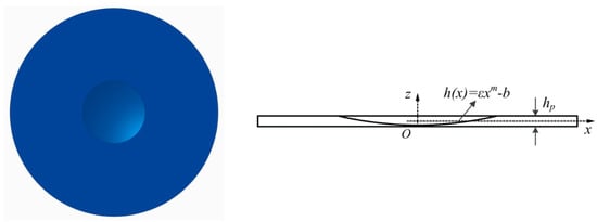
Figure 1.
A circular plate embedded with a two-dimensional acoustic black hole.
The existence of truncation makes the reflection coefficient of the flexural wave increase significantly, which will seriously affect the ABH effect [19]. Attaching a damping layer to the ABH region can significantly reduce the reflection of flexural wave and improve the efficiency of energy dissipation [20]. The ABH structures have exhibited obvious broadband characteristics for the aggregation effect of the flexural wave. These above characteristics of the acoustic black hole play an important role in applications such as vibration reduction [21,22], noise reduction, and energy recovery [23,24].
2.2. Theory of Transmission Loss
When sound waves are incident on a wall or partition, some of them will be reflected and some will be transmitted through the wall or partition. Figure 2 shows the propagation procedure of the sound wave when transmitting through an ABH circular plate. The transmission coefficient is defined as the ratio of transmitted energy to incident energy:
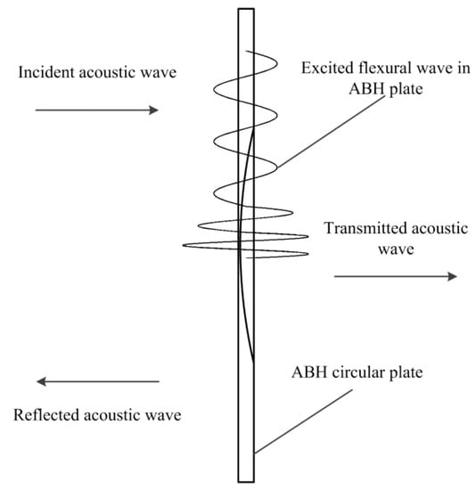
Figure 2.
Conceptual diagram of the sound wave propagating through an acoustic black hole (ABH) circular plate.
With the condition that the fluids on both sides of the plate are the same, the sound transmission loss of the circular plate can be expressed as:
For an infinite plate, the transmission coefficient at the (θ, φ) angle to the normal to the surface of the plate is:
where θ is the angle between the incident sound wave and the normal of the plate surface; φ is the angle of incidence with respect to the axis of the minimum stiffness of the plate; Z is the impedance of the flexural wave,; ρ0 is the density of the fluid; c0 is the velocity of the sound wave in the fluid. The diffuse field transmission coefficient can be obtained by determining the weighted average of the transmission coefficients of all incident angles:
For an isotropic plate, Equation (7) can be simplified to:
When the sound wave is incident normally and the thickness of the plate is much smaller than the wavelength of the sound wave, the transmission loss can be expressed as:
Sharp’s research showed that for a single-layer plate, the transmission loss in the range of mass law can be obtained by using a constant value of and the relationship between the sound transmission loss of field incidence and that of normal incidence in one-third octave band is [25]:
The sound transmission loss of a plate can be divided into several characteristic intervals by its first-order resonance frequency and critical frequency. According to the theory of elastic vibration, the natural frequency of a thin circular plate freely vibrating under the boundary condition that the edge is clamped can be expressed as:
where h is the thickness of the circular plate; r is the diameter of the circular plate; E is the Young’s modulus of the material; ρ is the density; ν is Poisson’s ratio; αnm is the coefficient. The first-order resonance frequency of the uniform circular plate can be obtained according to Equation (11).
The circular plate has a critical frequency (also known as the coincidence frequency), at which the velocity of the flexural wave in the plate is equal to the velocity of the sound wave propagating in the fluid. The critical frequency can be obtained by:
where c is the velocity of sound in the fluid, is the velocity of the longitudinal wave in the thin rod.
In practice, the TL of a plate is often lower than the calculated value according to the mass law, because the sound insulation performance of the plate is also related to its stiffness and damping. The sound insulation characteristics of a typical plate can be divided into four parts according to the frequency, which are called the stiffness-controlled region, the mass-controlled region, the coincidence-controlled region, and the damping-controlled region. In the stiffness-controlled region, the sound insulation of the plate is proportional to its stiffness, and decreases as the frequency increases. With the frequency increases, the resonant effect excites large amplitudes and produces an obvious transmission effect. The TL drops to a minimum at the first-order resonance frequency. Then, the effect of resonance gradually disappears with the frequency continuing to increase, and the vibration of the plate begins to be affected by the inertial mass, that is, into the mass-controlled region. When the frequency rises to a certain value, the projection of the wavelength of the incident sound wave on the plate is equal to the flexural wave wavelength of the plate. At this time, due to the bending stiffness effect, the sound wave excites the natural vibration of the plate, so that the sound insulation capability of the plate is greatly reduced. Finally, at very high frequencies, the transmission loss rises again and gradually approaches the extension of the mass law portion of the original curve, which is called the damping-controlled region.
When the frequency is in the range from 1.5 times the first-order resonance frequency of the plate to , at which in the mass-controlled region, the expression of field incident transmission loss is:
At greater than or equal to the critical frequency, the field incident transmission loss of the isotropic panel is:
While in the frequency domain of to the critical frequency, the TL can be approximated by linearly interpolating the corresponding two TL values of and critical frequency.
3. Finite element model (FEM) Analysis of Sound Transmission Loss of the ABH Circular Plate
3.1. FEM Model of Vibro-Acoustic Coupling
The sound insulation problem of an ABH circular plate is a vibro-acoustic coupling process. Assuming that the fluid medium is an ideal non-viscous medium, the Helmholtz equation for the steady-state sound field can be expressed as:
where is the Laplace Operator; k is the wave number, ; is the sound pressure; ω is the angular frequency; ρ0 is the density of the fluid. In the finite element calculation, the interpolation function is selected to represent the sound pressure:
where is the column vector of the sound pressure of the nodes and is the column vector of the shape function.
The pressure of the sound acting on the structure can be regarded as an additional normal load. Thus, the dynamic equation of the structural model can be written as:
where , , are the stiffness matrix, mass matrix, and damping matrix of the unconstrained part of the structural mesh; is the coupling stiffness matrix; is the excitation load, which includes the contribution of the constraint portion of the structure, the known load and the external sound pressure load p perpendicular to the surface of the structure.
At the location where the fluid and the structure are coupled, the vibration velocity in the normal direction of the structure is equal to the vibration velocity in the normal direction of the fluid. At the acoustic-solid coupling boundary, the vibration velocity of the structure can be regarded as the additional velocity input of the sound, and the acoustic equation can be written as:
where is the coupled mass matrix; is the excitation load, which contains the known sound pressure, the sound source in the acoustic field, and the contribution of the vibration velocity boundary.
Equations (17) and (18) can be written as a coupled equation in the form of a matrix:
3.2. FEM Modeling of TL Analysis
The geometric parameters of the model used for finite element analysis are shown in Table 1. The diameter and thickness of the circular plate are 400 mm and 4 mm respectively, the power index of ABH is m = 2, the diameter of the ABH region is 60 mm, and the truncation thickness is 0.5 mm, which are the same as shown in Figure 1.

Table 1.
Geometric parameters of the ABH circular plate.
Figure 3 shows the FEM model of the ABH circular plate and the vibro-acoustic coupled model for TL analysis. The ABH circular plate was meshed by solid elements and tetrahedral meshes, and the mesh size of the uniform region is 2 mm. In order to improve the calculation accuracy, the grid of the ABH region has a basic size of 1 mm and encrypts the mesh in the small curved area with a minimum size of 0.2 mm; thereby, each wavelength contains at least 10 elements to ensure calculation accuracy. The acoustic model has a size of 0.6 × 0.6 × 0.02 m. The calculated frequency has a corresponding relationship with the grid cell size. For the linear finite element model, the side length of the largest cell must be less than 1/6 of the wavelength corresponding to the highest calculated frequency, that is, . In this paper, the calculation frequency of the transmission loss is 0~10 kHz, so the cell length of the mesh should not be greater than 5.6 mm. Finally, the mesh size of the acoustic finite element model of this paper was selected as 4 mm.
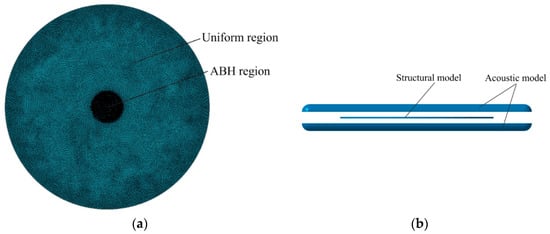
Figure 3.
Transmission loss (TL) analysis model of an ABH plate: (a) structural model of the ABH plate; (b) vibro-acoustic coupling model.
The FEM simulations were performed using the commercial software LMS Virtural.Lab. The acoustic model below the plate in Figure 3b represented the reverberation chamber, and the acoustic model above the plate represented the anechoic chamber. The ABH region of the circular plate was on the side close to the anechoic chamber, and the boundary condition of the periphery of the circular plate was clamped. A reverberation sound source was generated in the reverberation chamber, and the sound was transmitted to the anechoic chamber through the ABH plate, and finally passed through the outer wall surface of the anechoic chamber and radiated outward without reflection. The faces of the two acoustic meshes close to the structural mesh were coupled with the corresponding faces of the structural mesh and the remaining faces of the two acoustic meshes were respectively applied with a diffuse sound field on the side of the reverberation chamber and a zero reflection surface on the side of the anechoic chamber by the Automatic Matched Layer (AML) method. The transmission loss of the ABH plate can be obtained by computing the sound power incident on the ABH circular plate and radiated from the plate to the anechoic chamber.
The material parameters of the ABH circular plate are shown in Table 2. The first-order resonant frequency and the coincidence frequency of the ABH circular plate were equal to approximately 350 Hz and 2900 Hz according to Equations (11) and (12). Therefore, the calculated frequency of 0~10 KHz selected in this paper covers all characteristic frequency regions from the stiffness-controlled region to the damping-controlled region.
Table 2.
ABH FEA material properties.
3.3. Results of TL Simulation
The TL of an ABH circular plate with a diameter of 60 mm embedded in the center was calculated and compared with the sound transmission loss of the uniform circular plate, as shown in Figure 4. It can be seen from Figure 4 that, below the first-order resonance frequency, the TL of the circular plate embedded with the two-dimensional (2D) ABH is improved compared with the uniform circular plate and both the TLs of the two plates decrease as the frequency increases. At the first-order resonance frequency, the acoustic loss of the circular plate embedded with the acoustic black hole is greatly improved compared with the uniform circular plate. The difference between the TL of the ABH circular plate and the uniform circular plate at this frequency is 21.13 dB. In the mass-controlled region, the TL of the circular plate embedded with ABH is larger at some frequencies, while at other frequencies, the TL of the uniform circular plate is larger, indicating that the sound insulation performance of the ABH circular plate is not improved overall in this characteristic region. At the coincidence frequency, the TL of the ABH circular plate is 8.31 dB higher than that of the uniform circular plate. While in the damping-controlled region, the TL of the ABH circular plate is not improved overall, but at a certain frequency; for example, 8 kHz, there is an increase of 20 dB for the TL of the ABH circular plate.
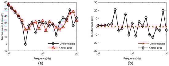
Figure 4.
TL of a circular plate embedded with a diameter of 60 mm acoustic black hole and the uniform circular plate: (a) TL values from 0 to 10 kHz; (b) TL differences of the two plates.
4. Experimental Validations
In order to verify the accuracy of the FEM analysis, an experimental platform for sound transmission loss measurement of ABH circular plates was constructed, which is shown in Figure 5. The four-microphone method of sound transmission in the standing wave tube [26,27] was adopted to measure and calculate the TLs of ABH circular plates. The signal generator generated a sinusoidal excitation signal with a frequency of 20 Hz~10 kHz, which was amplified by a power amplifier to drive the speaker to generate sound waves. Then, the sound wave entered the sound source tube to generate a plane incident wave. When the sound wave propagated to the ABH circular plate, part of the sound wave will be reflected to form a plane reflection sound wave, and the other part of the sound wave would be transmitted through the ABH circular plate into the receiving tube to form a plane transmitted sound wave. Two acoustic sensors were placed in front of and behind the ABH plate to measure the sound pressure at the location. The edge of the ABH circular plate was bonded to the standing wave tube with the transparent glass glue, which not only could fix the position of the ABH plate, but also ensured there was no gap between the edge of the ABH plate and the inner wall of the standing wave tube. The signals of the four acoustic sensors were collected and processed using the m + p acquisition terminal and the SO Analyzer data processing software.
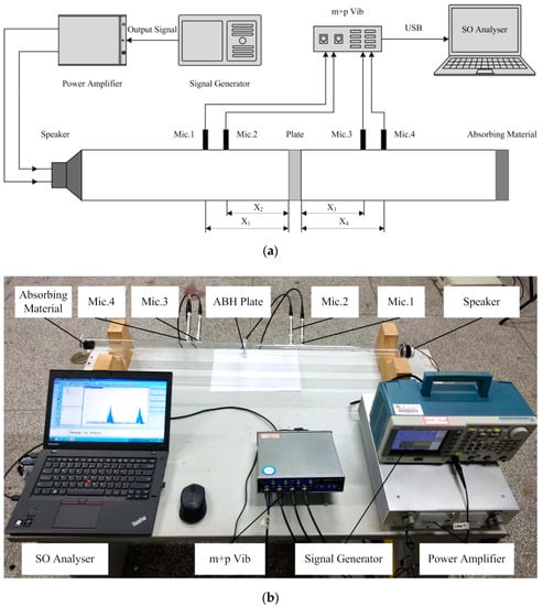
Figure 5.
Experimental setup for TL measuring: (a) Schematic of the experiment system; (b) photograph of the experiment system. Mic.:Microphone, Vib.:Vibration, SO:SmartOffice
The sound pressure transmission coefficient can be calculated by:
where p1, p2, p3, p4 are the sound pressures measured by four sensors and they can be expressed as and A and ωt are the amplitude and the phase of the sound pressures. Taking the sound pressure at Microphone 1 as a reference, the phases of the other three sound pressures are represented by the phase difference from that of the Mic. 1, and the transmission coefficient can be expressed as:
where A1, A2, A3, A4 are the amplitudes of the sound pressures measured by the four sensors; ωΔt2, ωΔt3, ωΔt4 are the phase differences between the sound pressures at Mic. 2, 3, and 4 and the sound pressure at Mic. 1.
Then, the transmission loss can be obtained by:
A fast Fourier transform was performed on the sound pressures measured at sensors 1, 2, 3, and 4. Taking the sound pressure at the sensor 1 as a reference signal, the amplitudes and relative phases at the corresponding frequencies in the spectrum can be obtained by FFT transform and crosspower-spectral calculation, and then substituted into Equations (21) and (22) for TL calculation.
Four specimens were manufactured for the TL measurement, which are shown in Figure 6. The materials of the specimens are aluminum and steel, respectively, and the geometric parameters of the ABH circular plates are as shown in Table 3. The thickness and diameter of the uniform circular plate are the same as the thickness of the uniform portion and the outer diameter of the ABH circular plate. The internal diameter of the standing wave tube is 36 mm, and the distance between sensors 1 and 2 and the distance between 3 and 4 are both 35 mm. The distances of sensors 2 and 3 from the surface of the specimen are .

Figure 6.
Four kinds of specimens for the TL test.
Table 3.
Geometric parameters of the ABH circular plate for TL measurement.
The transmission loss of the ABH circular plate calculated by FEM simulation and measured by experiment are compared in Figure 7. It can be seen from Figure 7 that the simulation result agrees well with the measured transmission loss of the ABH circular plate, which confirms the accuracy of the FEM modeling procedure and analysis in Section 3.

Figure 7.
Comparison between the results of simulation and experimental measurement.
The transmission loss values of the ABH circular plate and uniform circular plate manufactured by different materials measured by the experiment are shown in Figure 8. As can be seen from Figure 8a, the sound insulation performance of the ABH circular plate is better than that of a uniform circular plate in the range below the first-order resonance frequency and at some frequencies of the damping-controlled region. While in the mass-controlled region, the TL of the ABH circular plate is greater than that of the uniform circular plate at some frequencies, but lower at the other frequencies. The above experimental phenomena and trends are the same as those of the FEM analysis. It can be seen from Figure 8b that, when the ABH circular plate and uniform plate are manufactured with material of steel, the characteristics of their transmission loss are similar to those of transmission loss of ABH circular plate and uniform plate manufactured with aluminum whether in the stiffness-controlled region, the damping-controlled region, or the mass-controlled region.

Figure 8.
Experimental results of TL measurement for ABH circular plate and uniform plate: (a) TL of plates with aluminum material; (b) TL of plates with steel material.
5. Effects of ABH Parameters and Damping Layer
5.1. Effect of the ABH Diameter
To investigate the influence of the ABH diameter on the transmission loss of the circular plate, the TLs of a series of circular plates embedded with different ABHs with diameters of 10 mm~50 mm in the center were calculated, respectively, and they were compared with the TL of an ABH circular plate embedded with a diameter of 60 mm ABH, which is shown in Figure 9. It can be seen from Figure 9 that in the frequency range below 1 kHz, the sound transmission loss values of ABH circular plates ABH with different ABH diameters are substantially the same, and the TLs of a circular plate with an ABH diameter of 10 mm is 10.01 dB and 11.64 dB higher than those of a circular plate with ABH diameters of 60 mm and 20 mm at 4 kHz. In addition, in the range of 4 kHz~10 kHz, the sound transmission loss of the circular plate with ABH diameter of 10 mm is still higher than that of the circular plate with the ABH diameter of 60 mm. It can also be observed that, at almost all frequencies in the range of 1 kHz~10 kHz, the sound insulation performance of the circular plate with an ABH diameter of 30 mm is better than those of other ABH circular plates. Among them, the TL of a circular plate with an ABH diameter of 30 mm is 12.32 dB and 11.79 dB higher than those of a circular plate with an ABH diameter of 60 mm at 4 kHz and 5 kHz.

Figure 9.
TL of circular plates with different ABH diameters: (a) ABH diameter of 10~20 mm; (b) ABH diameter of 30~50 mm.
To summarize, for the circular plate studied above, there is an obvious promotion of the sound insulation performance when the diameter of the ABH is 30 mm. Furthermore, it can be concluded that there is a fixed value or interval of ABH diameter for a circular plate with a clamped boundary condition to obtain the best sound insulation performance. Whether the diameter of the ABH is below or above this specific interval, the sound insulation effect of the corresponding ABH circular plate will decrease. This may be because when the diameter of the ABH is 40~60 mm, the aggregation effect of the single acoustic black hole region on the flexural wave is no longer increased. On the contrary, due to the enlargement of the acoustic black hole region, a thin region with a large area and the thickness attenuated by power is formed, so that the areal density is sharply reduced at this region, which will significantly affect the sound transmission loss of the plate.
5.2. Effect of the ABH Orientation
Due to the axial symmetry, one side of the uniform thickness plate facing to the anechoic chamber is the same as the other side which is facing to the reverberation chamber. However, in the analysis of the sound transmission loss of the circular plate embedded with ABH, since the circular plate no longer had axial symmetry, the side with the ABH region could be placed on one side of the anechoic chamber or on the side of the reverberation chamber. For each plate of a different ABH diameter, the sound transmission loss values of the circular plates when the ABH region was toward the side of the anechoic chamber were compared with those values of the plates when the ABH region was toward the side of the reverberation chamber, as shown in Figure 10. It can be seen from Figure 10 that for the circular plate with the acoustic black hole with the diameter of 10 mm~60 mm in the center, the effect of ABH orientation change on the TL of the circular plate embedded with ABH is below 0.05 dB, and in the range of 100~3000 Hz, the TL change caused by the orientation of the ABH region is within 0.02 dB. It can be further concluded that for a circular plate structure embedded with single ABH, the orientation of the ABH region has little effect on the sound transmission loss of the plate.

Figure 10.
Effect of the orientation of the ABH region on the TL of the circular plate.
5.3. Effect of the ABH Number
The circular plates with ABH numbers of 7, 13, and 19 were selected for the TL analysis. The parameters of the ABH region are the same as those in Table 1, and the models are shown in Figure 11. Except for the ABH at the center of the circular plate, the rest of the ABHs are evenly distributed along the circumference, and the distance from the center of the ABHs to the center of the circular plate is indicated in Figure 11. For the plate with a number of ABHs of 7, the distance between the center of the central ABH and other six ABH centers is 80 mm; for the plate with a number of ABHs of 13, the distance between the center of the central ABH and other 12 ABH centers is 160 mm; for the plate with a number of ABHs of 19, the distances between the center of the central ABH and other 18 ABH centers are 80 mm and 160 mm, respectively.
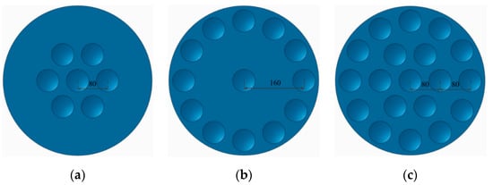
Figure 11.
Circular plates embedded with different numbers of ABHs: (a) 7 ABHs; (b) 13 ABHs; (c) 19 ABHs.
The sound transmission loss values of circular plates embedded with different numbers of ABHs are shown in Figure 12. It can be seen from Figure 12 that, below the first-order resonance frequency, the TL of the circular plate with the ABH number of 19 is significantly smaller than those of the ABH number of 1, 7, and 13, and the circular plate with ABH number 1 has the largest sound transmission loss. However, at the first-order resonance frequency, the plates ranked by the sound transmission loss values are 19ABH, 7ABH, and 13ABH, respectively, and the sound transmission loss is determined by the system damping at this frequency. In the mass-controlled region, the increase in the number of ABHs does not improve the TL of the plate as a whole, but at some specific frequencies, the TL is improved compared with that of the ABH number of 1, such as 800 Hz and 1250 Hz. While at the coincidence frequency, the TLs of circular plates with the ABH number of 7, 13, 19 are both smaller than that of the plate with the ABH number of 1, indicating that increasing the ABH number at the coincidence frequency cannot improve the sound transmission loss of the circular plate. It also can be concluded that in the damping-controlled region, the increase in the number of ABHs is also not able to increase the TL of the circular plate.
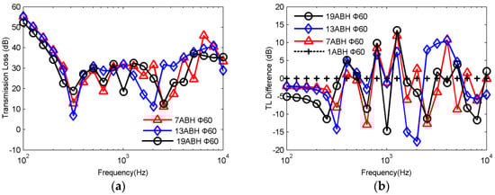
Figure 12.
TL of circular plates with different ABH numbers: (a) TL values of plates with ABH number of 7, 13, and 19; (b) TL value differences compared with single ABH plate.
The sound transmission loss values of circular plates with different ABH numbers were further compared with that of a circular plate of uniform thickness, and the results are shown in Figure 13. It can be seen from Figure 13 that the sound insulation performance of the circular plate with the ABH number of 1 is the best at the first-order resonance frequency and in the stiffness-controlled region. The TL of the circular plate with the ABH number of 1 is 21.13 dB larger than that of the uniform circular plate at 315 Hz. At the first-order resonance frequency, 630 Hz and 8000 Hz, the circular plate embedded with ABHs can significantly improve the sound insulation performance compared with the uniform thickness circular plate, but the increase of the number of ABHs at this time does not necessarily improve the sound transmission loss of the circular plate.

Figure 13.
Comparison of TL values between circular plates with different ABH numbers and the uniform circular plate.
To conclude, the embedding of the ABH structure into a circular plate can increase the sound transmission loss at some specific frequencies, but it cannot improve the sound transmission loss of circular plate in the entire frequency band. The increase in the number of ABHs is not able to increase the sound transmission loss at some specific frequencies, but rather reduces the sound transmission loss. The circular plate with single ABH exhibits good sound insulation effect at most frequencies. In applications, the appropriate number of ABHs should be selected according to the main frequency of the noise source.
5.4. Effect of the Truncation
Due to the limitations of the manufacturing process, the ideal ABH structure is difficult to implement in practice; thus, the actual acoustic black hole structure often has a truncation in the portion with a thickness close to zero. The existence of truncation in an ABH structure will seriously affect the aggregation effect of the flexural wave. The truncation thickness was set to 0.1 mm, 0.2 mm, 0.3 mm, and 0.4 mm, respectively, and the ε in Equation (1) was adjusted to ensure the diameter of ABH be 60 mm as the truncation thickness varying. Figure 14 shows the effect of the truncation thickness on the sound transmission loss of a circular plate embedded with 19 ABHs. It can be seen from Figure 14 that the TLs of the circular plate with a truncation thickness of 0.3 mm and 0.4 mm are substantially the same compared with that with a thickness of 0.5 mm in the range of 5 kHz and below, and they show a certain difference in the interval of 5 k~10 kHz. However, the above difference is significantly smaller than the difference between the circular plate with a truncation thickness of 0.1 mm, 0.2 mm and that with a truncation thickness of 0.5 mm. The ABH circular plates with truncation thicknesses of 0.1 mm and 0.2 mm have a TL reduction of 5.08 dB and 3.7 dB at the first-order resonance frequency, respectively. At most frequencies in the mass-controlled region, the circular plates with truncation thicknesses of 0.1 mm and 0.2 mm can significantly improve the sound transmission loss of the plate, and their TL values are very similar, among which their TL values are increased by 9.8 dB and 10.47 dB respectively at 1 kHz. At the coincidence frequency, the circular plate with a truncation thickness of 0.5 mm has the best sound insulation performance. While in the damping-controlled region, the reduction in the truncation thickness could increase the sound transmission loss at 8 kHz but does not increase the TL of the plate at other frequencies in this region.

Figure 14.
Effect of different truncation thickness on TL values of the ABH circular plate: (a) TL values of ABH plates with different truncation thickness; (b) TL value differences compared with the truncation thickness of 0.5 mm.
5.5. Effect of the Damping Layer
In the case of mechanical force excitation, the adhesion of a small amount of damping layer in the ABH region can significantly improve the adverse effect of the existence of the truncation on the flexural wave aggregation [28]. However, the influence of the damping layer under excitation of diffuse field needs to be further studied. A FEM model of an ABH circular plate attached with a damping layer was established, which is shown in Figure 15. The mesh size of the damping layer is 1 mm and an encryption was applied in specific areas. The damping layer has a thickness of 1 mm and a diameter of 60 mm, which can achieve full coverage of the ABH region. The damping layer is made of 3M ISODAMP TD 1604, and the damping material properties are shown in Table 4.

Figure 15.
FEM model of the ABH circular plate with a damping layer.
Table 4.
Damping material properties.
The thickness of the damping layer was selected as 1 mm, 1.5 mm, 2 mm, and 3 mm, respectively, in this study. Firstly, the influence of the thickness of the damping layer on the sound transmission loss of the circular plate embedded with 19ABHs was calculated, and each ABH region was attached with a damping layer, which is shown in Figure 16. It can be seen from Figure 16 that in the stiffness-controlled region, the thickness variation of the damping layer has almost no effect on the sound transmission loss of the circular plate. However, at the first-order resonance frequency, the larger the thickness of the damping layer is, the smaller the sound transmission loss is, indicating that the increase in the thickness of the damping layer reduces the sound transmission loss at the first-order resonance frequency. In the mass-controlled region, the attaching of the damping layer can significantly improve the sound transmission loss of the circular plate. However, the difference of TL values of the circular plate with the thickness of the damping layer varying from 1 mm to 3 mm is not obvious. At the coincidence frequency, the damping layer can also significantly improve the sound transmission loss. As can be seen from Figure 16b, the sound transmission loss of the ABH circular plate with the thickness of the damping layer of 2 mm is 19.68 dB higher than that without the damping layer. In the damping-controlled region, the attaching of the damping layer can also increase the sound transmission loss of the ABH circular plate at some frequencies, among which the TL of the ABH circular plate with a damping layer thickness of 3 mm is 14.35 dB higher than that of the ABH circular plate without the damping layer at 10 kHz.

Figure 16.
Effect of damping layer thickness on TLs of a circular plate containing 19 ABHs: (a) TL values of ABH plates with different thickness of damping layer; (b) TL value differences compared with undamped ABH circular plate.
Figure 17 shows a comparison of TL values of a circular plate embedded with damped 19ABHs to the TL of a uniform thickness circular plate. As can be seen from Figure 17, below the first-order resonance frequency, the sound transmission loss values of the damped ABH circular plates are lower than that of the uniform thickness circular plate, especially at the first-order resonance frequency, the TL of the ABH circular plate with a damping layer of 3 mm is 23.81 dB lower than that of the uniform thickness plate. At most frequencies of the mass-controlled region and the coincidence frequency, the sound insulation performance of the circular plate embedded with damped 19ABHs is better than that of the uniform circular plate. In the damping-controlled region, the TL values of the circular plates embedded with damped 19ABHs are improved at some frequencies, while reduced at other frequencies compared with that of the uniform circular plate.
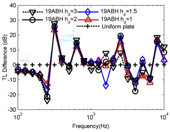
Figure 17.
Effect of damping layer thickness on TL of a circular plate containing 19 ABHs (compared with a uniform circular plate).
The effect of the thickness of the damping layer on the circular plate embedded with single ABH was further studied, as shown in Figure 18. It can be seen from Figure 18 that, below the coincidence frequency, there is almost no change in the sound transmission loss of the circular plate with damped ABH when the thickness of the damping layer varying from 1 mm to 3 mm, indicating that increasing the thickness of the damping layer could not significantly increase the TL at this frequency interval. At the first-order resonance frequency, all of the TL values of the circular plates with single damped ABH are lower than that of the circular plate with single undamped ABH. As can be seen from Figure 18b, the TL the circular plate with single damped ABH is much higher than that of the circular plate with single undamped ABH at the coincidence frequency, among which the difference between the TL of the ABH circular plate with a damping thickness of 1.5 mm and the circular plate with single undamped ABH is 10.74 dB. It also can be concluded that, in the damping-controlled region, the TL of the circular plate with single damped ABH is lower than that of the ABH circular plate without the damping layer at most frequencies when the thickness of the damping layer is 1 mm and 2 mm. The ABH circular plates with a damping thickness of 1.5 mm and 3 mm seem to have a better sound insulation performance in the damping-controlled region.
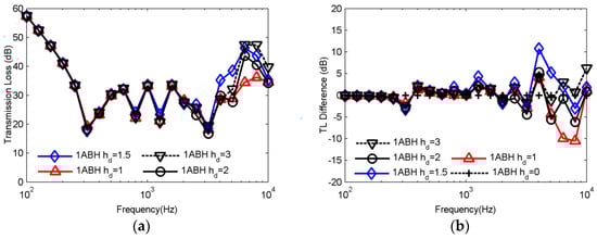
Figure 18.
Effect of damping layer thickness on TL of a circular plate embedded with single ABH: (a) TL values of ABH plates with different thickness of damping layer; (b) TL value differences compared with undamped ABH circular plate.
The sound transmission loss of a circular plate containing single damped ABH with different damping layer thicknesses was compared with that of a uniform thickness circular plate, and the results are shown in Figure 19. It can be seen from Figure 19 that below the first-order resonance frequency, the damping layer can improve the sound transmission loss of the circular plate embedded with single damped ABH, which is different from the case of the circular plate containing 19 ABHs. The TL of the circular plate with single damped ABH is 19.34 dB larger than that of the uniform circular plate at the first-order resonance frequency. In the mass-controlled region, single ABH with a damping layer can increase the TL of the circular plate at some frequencies, but at other frequencies the TL is reduced compared with that of the uniform circular plate. At the coincidence frequency, the TLs of circular plates containing single damped ABH are significantly lower than that of the uniform thickness circular plate. In the damping-controlled region, the sound transmission loss of circular plates containing single damped ABH can achieve a significant sound insulation effect only at 8 kHz compared with that of the uniform thickness circular plate, and at this time, the TL of the circular plate containing single damped ABH with a damping layer thickness of 3 mm is 20.83 dB higher than that of a uniform thickness circular plate.

Figure 19.
Effect of damping layer thickness on TL of a circular plate embedded with single ABH (compared with uniform circular plate).
The modal loss factor can reveal the mechanism of vibration suppression and radiated sound attenuation of acoustic black hole structures [29,30]. The modal loss factor of the ABH circular plate attached damping layers of different thicknesses was calculated in this paper, which is shown in Figure 20. As can be seen from Figure 20, in the range of 0~10 kHz, the increase of the thickness of the damping layer can significantly improve the modal loss factor of the ABH circular plate. The increase of the modal loss factor has a significant contribution to the vibration and noise attenuation of the structure in the full frequency domain under a mechanical force excitation [31]. Combined with the sound transmission loss data of Figure 20, it can be seen that although the modal loss factor of the ABH circular plate is greatly improved with the increase of the thickness of the damping layer in the whole frequency domain, the sound transmission loss of the ABH plate can be significantly affected only in the damping-controlled region. It can be concluded that although the damping loss factor of the ABH circular plate when the thickness of the damping layer is 1.5 mm is lower than that of the ABH circular plate with the thickness of the damping layer of 2 mm, the ABH circular plate with a damping layer thickness of 1.5 mm exhibits better sound insulation performance. The above phenomenon is different, as the larger the damping loss factor, the larger the vibration suppression or radiation sound attenuation caused by the modal loss factor under the excitation of a mechanical driving force. Therefore, when the ABH circular plate is applied to sound insulation, the sound insulation performance cannot be improved simply by increasing the thickness of the damping layer.
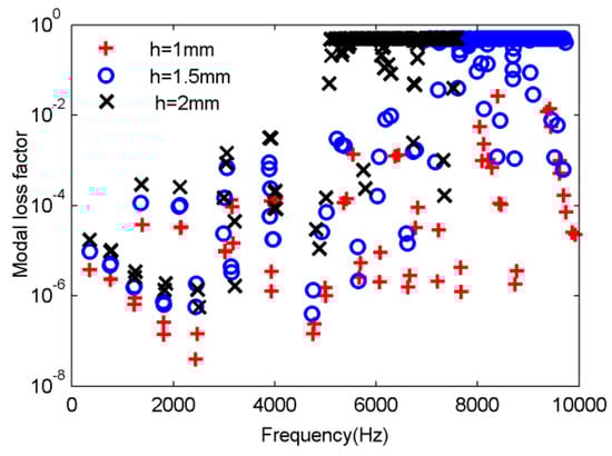
Figure 20.
Modal loss factor of ABH circular plate attached damping layers of different thicknesses.
6. Conclusions
In this study, a series of vibro-acoustic coupling finite element models for sound transmission loss (TL) analysis of different ABH circular plates were established by Automatic Matched Layer (AML) method and an experimental platform for sound transmission loss measurement of ABH circular plate was constructed. The accuracy of FEM modeling and analysis has been verified by the experimental measuring for transmission loss calculation results of ABH circular plates and uniform plates, in which the four-microphone method of sound transmission in the standing wave tube was adopted to compute the TLs. Both the experimental and simulation results show that the circular plate with a single ABH embedded in the center position can significantly improve the sound transmission loss in stiffness-controlled region, and at the first-order resonance frequency and some frequencies in damping-controlled region.
To investigate the influence mechanism of acoustic black hole parameters on sound transmission loss of ABH circular plates, the effects of diameter, orientation, number, and truncation thickness of ABHs on TLs of ABH circular plates have been analyzed. Numerical simulations reveal that there exists an interval of ABH diameter for an edge-clamped circular plate embedded with single ABH in the center position to obtain the best sound insulation performance, and the orientation of the ABH region has little effect on the sound transmission loss of the structure. It is also observed that the increase in the number of ABHs could not increase the sound transmission loss at some specific frequencies but rather reduces the sound transmission loss, and the ABH circular plates with truncation thicknesses of 0.1 mm and 0.2 mm have better sound insulation performance than those with other truncation thicknesses in the mass-controlled region. The effect of the damping layer on TL of circular plates embedded with 1 and 19 ABHs was also analyzed and the damping loss factors of the circular plate with single damped ABH of different damping layer thickness were compared. It can be concluded that the influence of damping layer mainly concentrates on the first-order resonance frequency and damping-controlled region of the plate, and at some frequencies, the greater the damping layer thickness, the worse the sound insulation performance, despite that the modal damping loss factor has been increased in the whole frequency domain.
Author Contributions
This study was initiated and designed by X.D. The set-up of the experimental platform and conducting of the experiments were done by X.D., D.H., and Q.F. The numerical simulations, experimental data analysis, and writing the paper were completed by X.D. J.Z. provided suggestions for experimental design and paper writing.
Funding
This research was funded by the Achievement Transformation Project of Nanjing (China), grant number 201701213.
Acknowledgments
The financial support from the Achievement Transformation Project of Nanjing (China) is gratefully acknowledged.
Conflicts of Interest
The authors declare no conflict of interest.
References
- Bowyer, E.P.; O’Boy, D.J.; Krylov, V.V.; Gautier, F. Experimental investigation of damping flexural vibrations in plates containing tapered indentations of power-law profile. Appl. Acoust. 2013, 74, 553–560. [Google Scholar] [CrossRef]
- Tang, L.; Cheng, L.; Ji, H.; Qiu, J. Characterization of acoustic black hole effect using a one-dimensional fully-coupled and wavelet-decomposed semi-analytical model. J. Sound Vibrat. 2016, 374, 172–184. [Google Scholar] [CrossRef]
- Georgiev, V.B.; Cuenca, J.; Gautier, F.; Simon, L.; Krylov, V.V. Damping of structural vibrations in beams and elliptical plates using the acoustic black hole effect. J. Sound Vibrat. 2011, 330, 2497–2508. [Google Scholar] [CrossRef]
- Conlon, S.C.; Fahnline, J.B.; Semperlotti, F. Numerical analysis of the vibroacoustic properties of plates with embedded grids of acoustic black holes. J. Acoust. Soc. Am. 2015, 137, 447–457. [Google Scholar] [CrossRef]
- Mironov, M.A.; Pislyakov, V.V. One-dimensional acoustic waves in retarding structures with propagation velocity tending to zero. Acoust. Phys. 2002, 48, 347–352. [Google Scholar] [CrossRef]
- Bowyer, E.P.; Krylov, V.V. Sound radiation of rectangular plates containing tapered indentations of power-law profile. In Proceedings of the Meetings on Acoustics 164ASA, Kansas, USA, 22–26 October 2012; Acoustical Society of America: Melville, NY, USA, 2012. [Google Scholar] [CrossRef]
- Bowyer, E.P.; Krylov, V.V. Experimental study of sound radiation by plates containing circular indentations of power-law profile. Appl. Acoust. 2015, 88, 30–37. [Google Scholar] [CrossRef]
- Bowyer, E.P.; Krylov, V.V. Damping of flexural vibrations in turbofan blades using the acoustic black hole effect. Appl. Acoust. 2014, 76, 359–365. [Google Scholar] [CrossRef]
- Feurtado, P.A.; Conlon, S.C. An Experimental Investigation of Acoustic Black Hole Dynamics at Low, Mid, and High Frequencies. J. Vib. Acoust. Trans. ASME 2016, 138. [Google Scholar] [CrossRef]
- Feurtado, P.A.; Conlon, S.C. Transmission loss of plates with embedded acoustic black holes. J. Acoust. Soc. Am. 2017, 142, 1390–1398. [Google Scholar] [CrossRef]
- Feurtado, P.A.; Conlon, S.C. Wavenumber transform analysis for acoustic black hole design. J. Acoust. Soc. Am. 2016, 140, 718–727. [Google Scholar] [CrossRef]
- Ma, L.; Cheng, L. Sound radiation and transonic boundaries of a plate with an acoustic black hole. J. Acoust. Soc. Am. 2019, 145, 164–172. [Google Scholar] [CrossRef] [PubMed]
- Ma, L.; Cheng, L. Topological optimization of damping layout for minimized sound radiation of an acoustic black hole plate. J. Sound Vibrat. 2019, 458, 349–364. [Google Scholar] [CrossRef]
- Li, X.; Ding, Q. Sound radiation of a beam with a wedge-shaped edge embedding acoustic black hole feature. J. Sound Vibrat. 2019, 439, 287–299. [Google Scholar] [CrossRef]
- Ji, H.L.; Wang, X.D.; Qiu, J.H.; Cheng, L.; Wu, Y.P.; Zhang, C. Noise reduction inside a cavity coupled to a flexible plate with embedded 2-D acoustic black holes. J. Sound Vibrat. 2019, 455, 324–338. [Google Scholar] [CrossRef]
- Wang, X.D.; Ji, H.L.; Qiu, J.H.; Cheng, L. Wavenumber domain analyses of vibro-acoustic decoupling and noise attenuation in a plate-cavity system enclosed by an acoustic black hole plate. J. Acoust. Soc. Am. 2019, 146, 72–84. [Google Scholar] [CrossRef]
- Han, B.; Ji, H.; Qiu, J.; Cheng, L. Formation of vibration attenuation in plate by inserting acoustic black hole indentations without damping layer treatment. In Proceedings of the 26th International Congress on Sound and Vibration, ICSV 2019, Montreal, QC, Canada, 7–11 July 2019; The International Institute of Acoustics and Vibration (IIAV): Auburn, AL, USA, 2019. [Google Scholar]
- Hook, K.; Cheer, J.; Daley, S. Optimal feedforward control of a beam with an active acoustic black hole termination. In Proceedings of the 26th International Congress on Sound and Vibration, ICSV 2019, Montreal, QC, Canada, 7–11 July 2019; The International Institute of Acoustics and Vibration (IIAV): Auburn, AL, USA, 2019. [Google Scholar]
- Krylov, V.V. New type of vibration dampers utilising the effect of acoustic ‘black holes’. Acta Acust. United Acust. 2004, 90, 830–837. [Google Scholar]
- Krylov, V.V.; Tilman, F. Acoustic ‘black holes’ for flexural waves as effective vibration dampers. J. Sound Vibrat. 2004, 274, 605–619. [Google Scholar] [CrossRef]
- Deng, J.; Zheng, L.; Zeng, P.Y.; Zuo, Y.F.; Guasch, O. Passive constrained viscoelastic layers to improve the efficiency of truncated acoustic black holes in beams. Mech. Syst. Signal Proc. 2019, 118, 461–476. [Google Scholar] [CrossRef]
- Lee, J.Y.; Jeon, W. Vibration damping using a spiral acoustic black hole. J. Acoust. Soc. Am. 2017, 141, 1437–1445. [Google Scholar] [CrossRef]
- Zhao, L.X.; Conlon, S.C.; Semperlotti, F. Broadband energy harvesting using acoustic black hole structural tailoring. Smart Mater. Struct. 2014, 23, 065021. [Google Scholar] [CrossRef]
- Zhao, L.X.; Conlon, S.C.; Semperlotti, F. An experimental study of vibration based energy harvesting in dynamically tailored structures with embedded acoustic black holes. Smart Mater. Struct. 2015, 24, 065039. [Google Scholar] [CrossRef]
- Bies, D.A.; Colin, H.; Carl, H. Engineering Noise Control, 4th ed.; E&FN Spon: London, UK, 2009; pp. 285–323. [Google Scholar]
- Qu, B.; Zhu, B. Four-microphone Method of Sound Transmission in the Standing Wave Tube. Noise Vib. Control 2002, 22, 44–46. [Google Scholar]
- Dong, L.; Wang, Y.-S.; Guo, H.; Liu, N.-N. Errors in the measurement of transmission loss in a standing wave tube. Noise Control Eng. J. 2017, 65, 174–182. [Google Scholar] [CrossRef]
- Denis, V.; Gautier, F.; Pelat, A.; Poittevin, J. Measurement and modelling of the reflection coefficient of an Acoustic Black Hole termination. J. Sound Vibrat. 2015, 349, 67–79. [Google Scholar] [CrossRef]
- Ma, L.; Zhang, S.; Cheng, L. A 2D Daubechies wavelet model on the vibration of rectangular plates containing strip indentations with a parabolic thickness profile. J. Sound Vibrat. 2018, 429, 130–146. [Google Scholar] [CrossRef]
- Conlon, S.C.; Fahnline, J.B.; Shepherd, M.R.; Feurtado, P.A. Vibration control using grids of acoustic black holes: How many is enough? In Proceedings of the 44th International Congress and Exposition on Noise Control Engineering, INTER-NOISE 2015, San Francisco, CA, USA, 9–12 August 2015; The Institute of Noise Control Engineering of the USA, Inc.: Reston, VA, USA, 2015. [Google Scholar]
- Du, X.F.; Huang, D.C.; Zhang, J.R. Dynamic Property Investigation of Sandwich Acoustic Black Hole Beam with Clamped-Free Boundary Condition. Shock Vibrat. 2019, 2019, 14. [Google Scholar] [CrossRef]


© 2019 by the authors. Licensee MDPI, Basel, Switzerland. This article is an open access article distributed under the terms and conditions of the Creative Commons Attribution (CC BY) license (http://creativecommons.org/licenses/by/4.0/).