Article

Extraction of Creation-Time for Recovered Files on Windows FAT32 File System

1
Department of Computer Science, Dongduk Women’s University, Seoul 02748, Korea
2
Department of Informatics, Gyeongsang National University, Jinju 52828, Korea
3
Department of Computer Science and Engineering, Korea University, Seoul 02841, Korea
*
Author to whom correspondence should be addressed.
Appl. Sci. 2019, 9(24), 5522; https://doi.org/10.3390/app9245522
Submission received: 16 November 2019 / Revised: 6 December 2019 / Accepted: 11 December 2019 / Published: 15 December 2019
(This article belongs to the Section Computing and Artificial Intelligence)

Abstract

:
In this article, we propose a creation order reconstruction method of deleted files for the FAT32 file system with Windows operating systems. Creation order of files is established using a correlation between storage locations of the files and their directory entry locations. This method can be utilized to derive the creation-time bound of files recovered without the creation-time information. In this article, we first examine the file allocation behavior of Windows FAT32 file system. Next, based on the examined behavior, we propose a novel method that finds the creation order of deleted files after being recovered without the creation-time information. Due to complex behaviors of Windows FAT32 file system, the method may find multiple creation orders although the actual creation order is unique. In experiments with a commercial device, we confirm that the actual creation order of each recovered file belongs to one of the creation orders found by the method.

1. Introduction

Even though a file is deleted intentionally or systematically, the deleted file remains in the storage space until new files overwrite its storage space. When a deleted file is recovered from the storage space, the time information in the metadata of a recovered file is occasionally unavailable or incorrect. The recovered file without the metadata of creation-time may lose the useful information when the files were generated. When it is suspected that a recovered file is associated with crimes or frauds, the creation-time of the recovered file plays an important role in digital forensics, i.e., verifying whether the recovered file was created before or after target criminals. Especially, the creation-time is very important for recovered multimedia files because still images or video files frequently contain critical scenes providing crucial evidence for criminal investigation and accident site examinations. The creation-time of recovered multimedia files verifies exactly when the recorded critical scenes occurred, and whether or not the recorded critical scenes are related to target criminals and accidents.
While many studies for detecting the forged document, identifying the source digital device of multimedia, and recovering deleted files have been done [1,2,3], a little progress has been done for creation-time reconstruction of files recovered without the metadata of creation-time. In this article, we propose a creation order reconstruction method for recovered files upon the FAT32 file system with Windows operation systems. The creation order of files is utilized to derive the creation-time bound of files recovered without the meta information of creation-time. Figure 1 shows an example of utilizing the creation order of a recovered video file without the time-related meta information. A video file loses its time-related meta information, when its file header containing the creation-time is not recovered while its video contents are partially recovered, as shown in Figure 1. If the creation order of the recovered file is between file B and file C, the lower bound of its creation-time is 05 May 02:20 and the upper bound is 05 May 02:30. This means that the image scenes in the recovered video file were recorded at later than 05 May 02:20 and earlier than 05 May 02:30. If the creation order of the recovered file is between file X and file Y, the image scenes in the recovered video file were recorded at later than 02 June 04:00 and earlier than 02 June 04:10.
Most of related digital forensic studies focused on multimedia tamper detection, source camera identification, or hidden data recovery [1,2,3]. The previous studies for the multimedia tamper detection can be classified into two groups: active intrusive approach and passive blind approach. In the active intrusive approach, a known identifier trace such as a signature or watermark is embedded imperceptibly into the multimedia contents at the time of recording and it is utilized to discover tampering evidence of the forged multimedia [4]. In the passive blind approach, descriptive features such as camera sensor artifacts, coding artifacts, and material object features are extracted from the multimedia data without help of signatures or watermarks and they are analyzed to detect abnormal patterns of forged multimedia [5,6]. The previous studies for the source camera identification investigated unique characteristics of digital devices such as lens radial distortion, sensor imperfections, color filter array interpolation, codec parameters, etc. in order to identify the specific model of source digital devices [1,7,8].
Our study belongs to the category of hidden data recovery. The previous studies for the hidden data recovery investigated how to search and extract artifacts of deleted data upon unallocated storage space of camera devices and how to assemble found fragments [3,9]. Most of previous studies [10,11,12,13,14,15] have employed the carving technique that searches exhaustedly artifacts of deleted files upon unallocated storage space of camera systems. For more efficient searching operation, some of them [13,14,15] utilized a specific unique header and a footer signature of deleted data format. This signature-based carving approach searches for the unique signature of still image or video files and extracts the data between the signatures. Recent carving methods [16,17,18] considered the case that a deleted file is split into multiple fragments and the fragments are spread in non-continuous locations. They search for spread fragments and combines them into a single file based on the information of fragment size and fragment location in the video file. However, all of these previous methods did not consider the reconstruction of lost creation-times of recovered files.
As a branch of hidden data recovery, some previous studies [19,20,21,22,23] dealt with a problem of reconstructing the creation order, called timeline, of huge events with heterogeneous time-related metadata. These studies focused on designing a framework that automatically generates the timeline of massive events obtained from different devices. However, they required time-related metadata and thus are not applicable to recovered files without the metadata of creation-time. Only a few studies [24,25,26,27] addressed the automatic timeline reconstruction of files without the metadata of creation-time. They are designed on the basis of the file allocation pattern of file systems. Tse [24] examined a statistical relationship between the file allocation sequence and the file creation-times. This statistical relationship cannot be utilized to reconstruct the deterministic creation order of recovered files, because it provides just non-deterministic probability information for the creation-time. Minnaard [25] investigated the file allocation pattern of Linux FAT32 file system and revealed that relative positions of files on the storage device are directly related to their creation order. The relationship between file locations and their creation order is utilized to derive the creation-time bound of recovered files. Lee et al. [26] analyzed the complexity of creation order reconstruction for Linux FAT32 file system. These two methods [25,26] are applicable only to Linux FAT32 file system, but not to Windows FAT32 file system. Willassen [27] analyzed characteristics of Windows NTFS file system [15] in order to detect the antedating of files. This method is applicable only to Windows NTFS file system but not to Windows FAT32 file system, while the FAT32 file system is widely deployed in commercial storage devices and popularly used in removable SD flash memory cards.
It is the allocator of the file system in a kernel’s deriver that determines which of storage space each file is allocated to. In this article, we propose a novel method that constructs the creation order of recovered files upon the Windows FAT32 file system. Windows operation systems are adopted by many commercial multimedia devices, for example, Nokia Lumia smart phone, HP Stream tablet, Microsoft Surface tablet, Pupug In-dash navigation, etc. We first examine the file allocation behavior of Windows FAT32 file system through elaborate experiments of recent Windows operation systems such as Windows XP, Windows 7, Windows 8.1, and Windows 10. Next, on the basis of the verified behavior of Windows FAT32 file system, we design a creation order reconstruction method. Creation order of files is established using both the correlation between storage locations of files and their creation order, and the correlation between directory entry order of files and their creation order. The creation order can be utilized to derive the creation-time bound of files recovered without the creation-time information. The lower bound of a recovered file is the creation-time of the neighboring front file in the creation order, and the upper bound is the creation-time of the neighboring rear file. The proposed method may find multiple creation orders against a single recovered file due to complex analysis of Windows FAT32 behaviors, although the actual creation order is unique. The proposed method is bounded to non-fragmented file allocations, where fragmented file allocations occur rarely only when the storage space is fully occupied. Also, the method discards wasted storage space of file systems, called slack space, whereas some previous studies [6] exploited it. In experiments with a commercial device, we confirm that the real creation order of each recovered file belongs to one of the creation orders found by the proposed method. The method finds fewer creation orders against a recovered file, where the number of generated files or the number of deleted files is smaller.
The rest of this article is organized as follows. Section 2 explains the structure of FAT32 file system and describes the file allocation characteristics of Windows FAT32 file system. Section 3 explains the proposed creation order reconstruction method in detail. Section 4 deals with practical evaluations of the proposed method. Section 5 concludes this article with discussions for further study.

2. File Allocation Behavior of Windows FAT32 File System

Figure 2 shows the structure of the FAT32 file system, where the storage device is managed with three separate areas: reserved area, file allocation table(FAT) area and data area [28,29]. In the reserved area, the basic information for the file system is stored such as boot code, partition information, size of the addressable minimum block in the data area, etc. In the file allocation table(FAT) area, the offsets allocated to each file are stored as a linked list. In the data area, the contents of each file and meta information of files are stored. The data area is divided into multiple addressable minimum units, called clusters. Contents of each file are recorded in one or more clusters. A cluster stores the contents of at most one file, even when the cluster size is larger than the size of recorded contents.
Some cluster stores the meta information of stored files in a form of directory entry, instead of file contents. Figure 3 shows the structure of a directory entry that contains the meta information of a single file. The directory entry includes file name, attributes, creation-time, last access time, write time, the first cluster allocated to storing of file contents, and the number of clusters allocated to storing file contents. The directory entry of a deleted file remains with a deletion mark `0xE5’ in the first byte of the file name field until it is overwritten by recording the meta information of another new file. The size of the directory entry is 32 bytes for a file name with 8 bytes or less. For a long file name with larger than 8 bytes, the size of the directory entry is multiple of 32 bytes, depending on the size of the file name. In this paper, the cluster storing file contents is referred to as content cluster and the cluster storing directory entries is referred to as directory entry cluster.
Because there is no public reference for the Windows FAT32 implementation [26], it is imperative to empirically examine the file allocation pattern on Windows-family operating systems. We examine the file allocation pattern in detail upon Lumia 630 smartphone with Windows 10 Mobile and personal computers with Windows XP SP3, Windows 7 Home Basic, Windows 7 Professional, Windows 7 Ultimate 64 bit Edition, Windows 8.1, Windows 8.1 Pro, Windows 10 Home, or Windows 10 Pro. We dump the binary image of external storages using FTK Imager tool after storing new files or deleting files, and interpret all binary codes of the dumped image using WinHex or HxD tool. Elaborate interpretation of their file allocation patterns results in some common behaviors, which are summarized in the following subsections.

2.1. Allocation of Content Clusters to Store File Contents

The Windows FAT32 file allocator searches for available clusters linearly from the beginning of the data area. The Windows FAT32 file allocator searches according to the next fit algorithm that skips available spaces smaller than the size of a file being stored. The reference to the cluster lastly allocated is stored in the FSI_Nxt_Free field of the FSINFO structure, which exists in the reserved area of the FAT32 file system. The Windows FAT32 file allocator searches for available space from the FSI_Nxt_Free reference. If some files located before the FSI_Nxt_Free reference are deleted, the value of the FSI_Nxt_Free field is updated with the lowest index among clusters allocated to the deleted files. We refer to the file allocation pattern of Windows FAT32 file system as deletion-backward next fit algorithm.
Figure 4 shows an example of the deletion-backward next fit pattern. In Figure 4a, files A–E are allocated sequentially and next files B and D are deleted. Then the FSI_Nxt_Free pointer is changed from 16 to 4, where 16 is the cluster index behind the lastly allocated cluster and 4 is the lowest index among clusters of deleted files. In Figure 4b, another file F with a size of three clusters is additionally allocated. The Windows FAT32 file allocator searches three clusters continuously available from cluster 4 pointed by the FSI_Nxt_Free reference. Cluster 4 and cluster 5 are skipped because their continuously available size is smaller than the file size. Cluster 9, cluster 10 and cluster 11 are allocated to file F because their continuous available size is equal to or larger than the file size.
If the search of the file allocator reaches the end of the data area, the search is wrapped around and restarted at the beginning of the data area. File fragmentations occur only after the file allocator reaches the end of the data area, because the Windows FAT32 file allocator searches continuously available clusters before reaching the end of the data area. If there exist data behind the tail of allocated clusters, the file allocator already reached the end of the data area in the past [25,26]. That is, if there is no data behind the tail of allocated clusters, the file allocator never reaches the end of the data area and thus there is no file fragmentation. Because the start point of file allocation moves back whenever deleting a file, the file allocator reaches the end of the data area when the space of the data area is fully occupied.

2.2. Allocation of Directory Entries to Record Meta Information of Files

In the FAT32 file system, each directory entry records the meta information of its corresponding file. The directory entry contains the file creation-time and the offset of clusters allocated to storing of file content. The first directory entry records the meta information of a system file, which is never deleted. Directory entries are usually stored in the first available cluster of the data area, which is called directory entry cluster in this paper. If there is no more available space in the selected directory entry cluster, another available cluster is allotted to recording of directory entries.
In the Windows FAT32 file system, searching an available directory entry of a new file works mostly in accordance with the next available algorithm. The file system searches for an available directory entry space sequentially from the recently assigned directory entry. When it reaches the end of a directory entry cluster, it goes back to the beginning of the cluster and searches sequentially for an available directory entry space among assigned directory entries. An assigned directory entry becomes available with a deletion mark `0xE5’ in the first byte when its corresponding file is deleted. If the file system fails to find an available directory entry space due to full assignment, it allots another available cluster as an additional directory entry cluster and searches for an available directory entry space sequentially from the beginning of this cluster. After assigning the last directory entry space of this cluster, it goes back to the beginning of the firstly allotted directory entry cluster and search sequentially until it reaches the end of the lastly allotted directory entry cluster. We refer to this allocation pattern of directory entry space on the Windows FAT32 file system as wrap-around next available algorithm. The meta information of recently deleted files still remains in their corresponding directory entries until the file system selects them in order to record meta information of new files only after searching the end of the lastly allotted directory entry cluster. If the meta information of a deleted file remains in its corresponding directory entry, the exact creation-time of a deleted file can be retrieved by matching the cluster offset of the recovered file in the data area with the meta information of all directory entries.
Although the cluster allocation patterns explained in Section 2.1 are addressed in the Minnaard’s study [25], the directory entry allocation patterns explained in Section 2.2 are newly verified in our study. Our method is designed by utilizing both the cluster allocation patterns and the directory entry allocation patterns of the Windows FAT32 file system.

3. Proposed Method to Extract Creation-Time Bound

3.1. Working Mechanism of Proposed Method

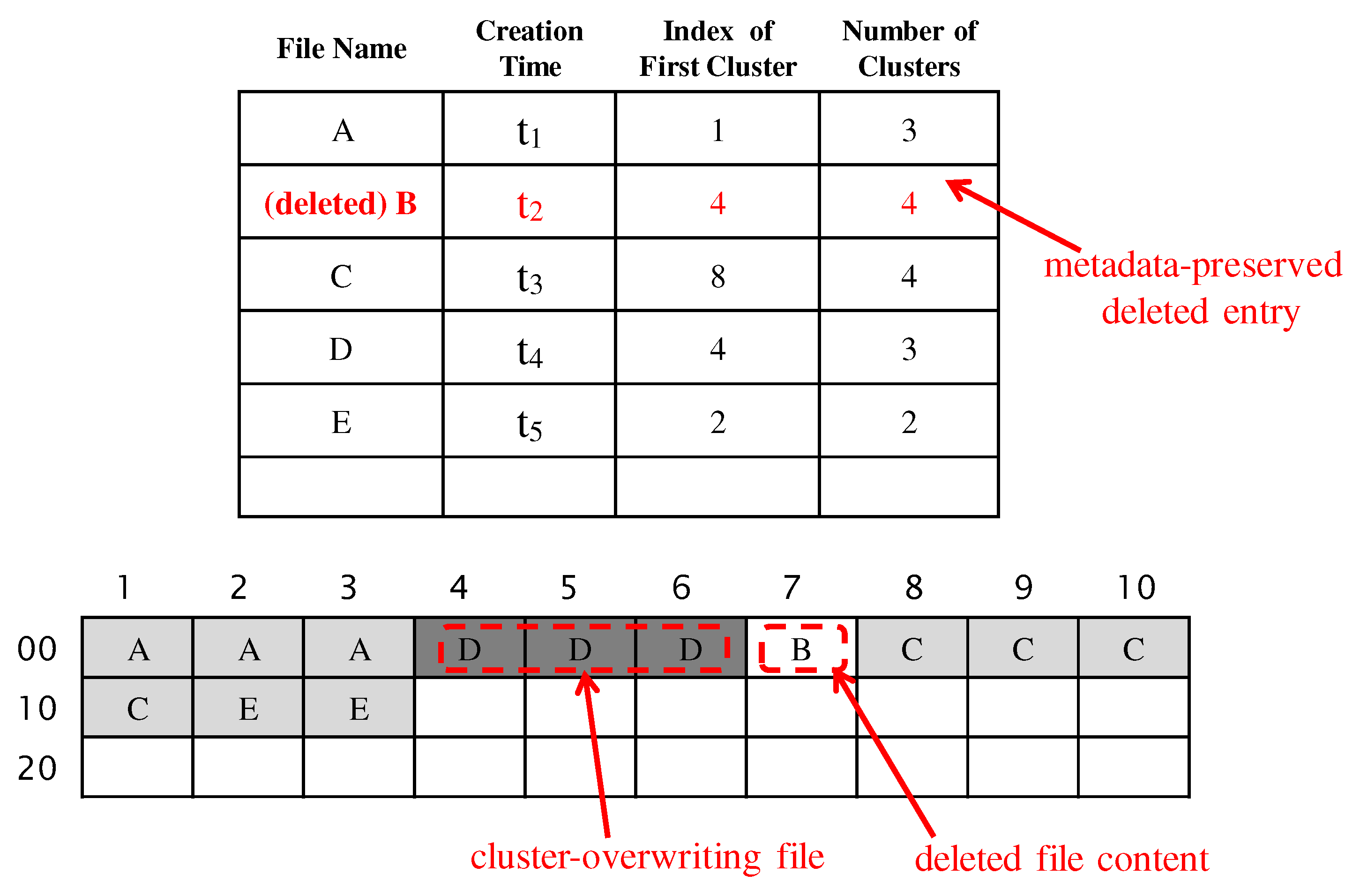
In this subsection, we explain how to derive the creation-time bound of a recovered file. If the meta information of a recovered file remains in one of the directory entries, we can easily recover its exact creation-time by matching the cluster offset of a recovered file with the location-related meta information of directory entries. In the directory entries of deleted files, the first byte of the file name field is set with the deletion mark ‘0xE5’. Figure 5 shows an example, where the data area is composed of a single directory entry cluster and 30 content clusters (for the sake of simplicity, only a part of meta information in directory entries is depicted and a directory entry cluster is omitted. Also, a few content clusters are given although the number of content clusters in practical storage devices is very large.). In this example, at first file A, file B and file C are allocated sequentially. Next, file B is deleted. At last file D and file E are allocated sequentially. When a partial contents of file B are recovered using the existing forensic tools [16,17], all meta information of file B can be reconstructed by matching the cluster offset of the recovered file and the location-related meta information of directory entries. Because the start offset of deleted file B is 4 and the number of allocated clusters is 4, the cluster offsets allocated to file B are 4, 5, 6 and 7. Hence the contents recovered from the cluster offset 7 are corresponding to file B. If there are two or more directory entries matched with the cluster offset of the recovered file, the directory entry with the latest creation-time is selected. The meta information in the matched directory entry contains the exact creation-time of the recovered file.
When the directory entries of deleted files are eliminated by recording the meta information of new files, the reconstruction of creation-time becomes complex. Figure 6 shows an example where the directory entries of deleted files are eliminated. There are two directory entry clusters, each of which consists of six directory entries as shown in Figure 6a and whose depictions are omitted in Figure 6b for the sake of simplicity. In this example, at first file A, file B, file C, file D, file E, and file F are allocated sequentially. Next file D is deleted and file G is allocated. Next file B, file G and File F are deleted. At last file H, file I, file J and file K are allocated sequentially. The directory entries of deleted files B, D, G and F are eliminated by recording the directory entries of other files. Figure 6a shows directory entries that are established according to the wrap-around next available algorithm. In this figure, → means the overwriting replacement of metadata. Figure 6b shows content clusters in the data area that are established according to the Deletion-backward Next Fit algorithm. In this figure, a box filled with light gray denotes a cluster containing a non-deleted file, a box filled with dark gray denotes a cluster containing a deleted file, and a box filled with white denotes a cluster never allocated. Names of deleted files in dark gray boxes are depicted for the sake of readability, although they disappeared when their corresponding directory entries are overwritten.
The proposed method traces the file creation event sequence using both the stored pattern of directory entries and the file allocation pattern of content clusters, explained in Section 2.1 and Section 2.2, respectively. First, the proposed method retrieves the file creation event sequence from the stored pattern of directory entries with some hidden marks for deleted events. Table 1 shows notations used to formally describe our trace analysis in this paper. The notation ? denotes a single hidden event of a deleted file, and the notation * denotes uncertain number (none, single, or multiple) of continuous hidden events of deleted files. When file X is stored in the directory entry position of ? i , it is denoted as X i . Then the entire sequence of file creation events in Figure 6a can be represented with
A , ? 1 , C , ? 2 , E , ? 3 , 4 , H 1 , I 2 , J 3 , K ,
because the directory entries are established according to the wrap-around next available algorithm. In Equation (1), 4 represents uncertain number (none, single, or multiple) of continuous hidden creation events between immediately before the wrap-around search for an available directory entry and immediately after the wrap-around search. For example, the creation event of file G between the creation event of file F and the creation event of file H. We cannot exactly know how many creation events are hidden due to traceless directory entry overwriting between before the wrap-around search and after the wrap-around search. When the notation ( ) denotes the sequential file creation event flow from the beginning of direction entries to their end as explained in Table 1, Equation (1) can be replaced with two sequential file creation event flows, which are represented with
( A , ? 1 , C , ? 2 , E , ? 3 ) 4 ( H 1 , I 2 , J 3 , K ) .
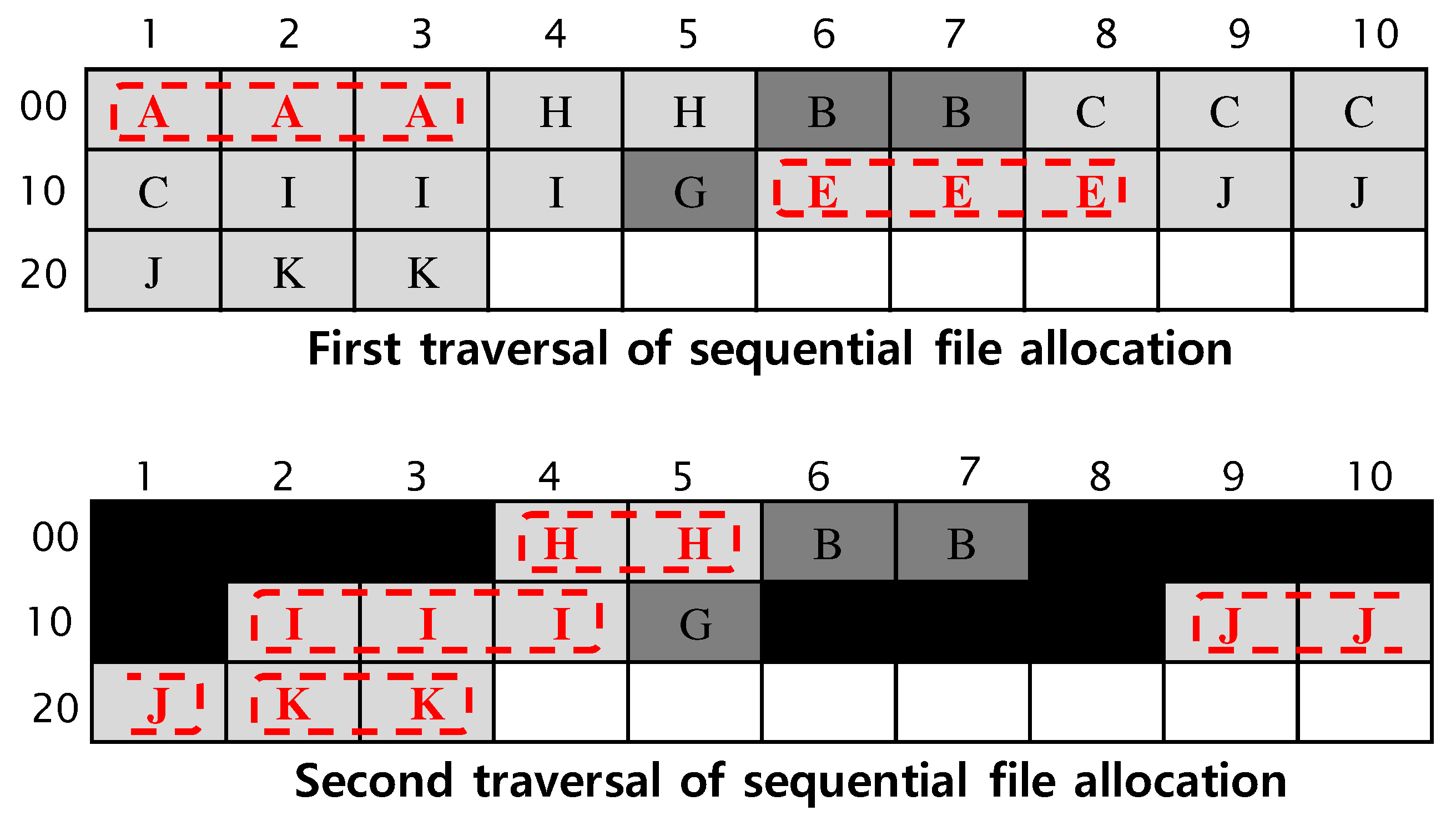
Next, the proposed method retrieves the file allocation sequence from the file allocation pattern of content clusters. Figure 7 shows the analysis procedure of the file allocation pattern of Figure 6b. The top figure in Figure 7 shows the first traversal of sequential file allocation according to the Deletion-backward Next Fit algorithm. The boxes with broken lines denote the selected files during the traversal. When the notation [ ] denotes the sequential file allocation flow from the beginning of content clusters to their end as explained in Table 1, the first sequential file allocation traversal is [ A , a , ? b , C , c , ? d , E ] . The notation ? b represents the deleted file in clusters 6 and 7, and the notation ? d represents the deleted file in cluster 15. The notations a and c represent an uncertain number of file allocations hidden under file H and file I, respectively. We cannot exactly know how many file allocations are hidden under overwriting file allocation. If clusters 4 and 5 contain file B, the notation a represents none event. If clusters 4 and 5 contain a single file different to file B, the notation a represents a single deleted file. If clusters 4 and 4 contain two files different to file B, the notation a represents two deleted files. The bottom figure in Figure 7 shows the second traversal of sequential file allocation according to the deletion-backward next fit algorithm, where the clusters used in the first traversal are excluded. Boxes filled with black denote the excluded clusters. The second sequential file allocation traversal is [ H , I , J , K ] . During the second traversal, cluster 6 and cluster 7 are skipped because their size is smaller than the size of file I. Also, cluster 15 is skipped because its size is smaller than the size of file J. Hence the overall file allocation sequence in Figure 6b can be represented with
[ A , a , ? b , C , c , ? d , E ] [ H , I , J , K ] .
The creation order of deleted files must be one of the creation orders of ? 1 , ? 2 , ? 3 and 4 . The creation orders of ? 3 and 4 are substantially the same as between E and H, which means that their lower bound of creation-time is the creation-time of file E and their upper bound is the creation-time of file H. In order to reduce the number of candidates for the creation order, we apply the following properties whose proofs are given in the Appendix A.
Property 1.
the creation-time of a partially overwritten file is earlier than that of a file overwriting the partially overwritten file.
Property 2.
if there are
( , ? i , , ? i + 1 , , ? i + 2 , ) ( , X i , ? j i + 1 , Y i + 2 , )
in the file creation event sequence and
[ X , a , ? b , Y , ] ,
in the file allocation sequence, then ? j i + 1 is a candidate of creation event only for the file recovered from a or ? b , but not for the other recovered files.
In the example of Figure 6, ? 1 in Equation (2) is a candidate of creation event only for the file recovered from ? b in Equation (3) according to Property 2. ( A , ? 1 , C ) is a simple form of Equation (4) where A, ? 1 and C are continuous file creation events. Also ? 2 in Equation (2) is a candidate only for the file recovered from ? d in Equation (3). After applying Property 1 and Property 2, the final candidates for the file recovered from ? b are ? 1 and ? 3 (or 4 ). This means that the creation-time of the file recovered from ? b is located between the creation-time of file A and that of file C, or between the creation-time of file E and that of file H. The final candidates of the file recovered from ? d are ? 2 and ? 3 (or 4 ).
Figure 8 shows another example which is continued from the example of Figure 6. File K, file L, and file M are allocated sequentially. Next file J, file C and file L are deleted sequentially. At last file N, file O, ⋯, file R and file S are allocated sequentially. Figure 8a shows the directory entries that are established according to the Wrap-around Next Available algorithm. The directory entries of deleted files C, J and L are eliminated by recording the directory entries of files Q and R respectively. Then the file creation event sequence in Figure 8a can be represented with
( A , ? 1 , ? 2 , ? 3 , E , ? 4 ) 5 ( H 1 , ? 6 2 , I 3 , ? 7 4 , K , ? 8 , M , N , O , P ) 9 ( Q 6 , R 7 , S 8 ) .
There are three sequential file creation event flows through two directory entry clusters: ( A , ? 1 , ? 2 , ? 3 , E , ? 4 ) , ( H 1 , ? 6 2 , I 3 , ? 7 4 , K , ? 8 , M , N , O , P ) and ( Q 6 , R 7 , S 8 ) . Figure 8b shows content clusters that are established according to the deletion-backward next fit algorithm. Similar to Figure 6b, boxes filled with dark gray denote clusters containing a deleted file, and names of deleted files in dark gray boxes are depicted for the sake of readability although they disappeared actually.
Figure 9 shows the analysis procedure of the file allocation pattern of Figure 8b. The top figure in Figure 9 shows the first traversal of sequential file allocation according to the deletion-backward next fit algorithm. The first sequential file allocation traversal is [ A , a , ? b , c , ? d , E ] . The notation ? b represents the deleted file in clusters 6 and 7, and the notation ? d represents the deleted file in cluster 15. The notation a represents uncertain number of file allocations hidden under file H, and The notation c represents an uncertain number of file allocations hidden under file N, file O and file I. We cannot exactly know how many file allocations are hidden under overwriting file allocation. The middle figure in Figure 9 shows the second traversal of sequential file allocation according to the Deletion-backward Next Fit algorithm, where the clusters selected in the first traversal are excluded. The second sequential file allocation traversal is [ H , ? b , c , I , ? d , e , ? f , K , ? g , M ] . The notation ? f represents the deleted file in cluster 21, and the notation ? g represents the deleted file in cluster 24. The notation e represents an uncertain number of file allocations hidden under file P. The bottom figure in Figure 9 shows the third traversal of sequential file allocation according to the Deletion-backward Next Fit algorithm, where the clusters selected in the first and the second traversals are excluded. The third sequential file allocation traversal is [ N , O , P , Q , R , S ] . During the third traversal, cluster 15, cluster 21 and cluster 24 are skipped because their size is smaller than the size of an allocating file. Hence the overall file allocation sequence in Figure 8b can be represented with
[ A , a , ? b , c , ? d , E ] [ H , ? b , c , I , ? d , e , ? f , K , ? g , M ] [ N , O , P , Q , R , S ] .
The creation order of deleted files must be one of the creation orders of ? 1 , ? 2 , ? 3 , ? 4 , 5 , ? 6 , ? 7 , ? 8 and 9 in Equation (6). The creation orders of ? 1 , ? 2 and ? 3 are the same as between A and E, and the creation orders of ? 4 and 5 are the same as between E and H. In order to reduce the number of candidates, we apply another following property.
Property 3.
if there are
( , X , ? j , Y , )
without ? behind Y in the file creation event sequence and
[ , X , ? a , Y , ] ,
without ? (or *) behind Y in the file allocation sequence, then ? j is the creation event of the file recovered from ? a .
In the example of Figure 8, ? 6 , ? 7 , ? 8 and 9 in Equation (6) are excluded from the candidates for ? b in Equation (7) because file ? b is earlier than file H according to Property 1. The final candidates of the file recovered from ? b are ? 1 and ? 4 . For the candidates of ? d , ? 7 , ? 8 , and 9 are excluded according to Property 1, and ? 6 is excluded according to Property 2. The final candidates of the file recovered from ? d are ? 1 and ? 4 . For the candidates of ? f , 9 is excluded according to Property 1, and ? 6 and ? 8 are excluded according to Property 2. The final candidates of the file recovered from ? f are ? 1 , ? 4 and ? 7 . For the file recovered from ? g , the final creation order is ? 8 according to Property 3.

3.2. Developed Software Tool

Our method was implemented into a software tool (Our developed tool can be found at http://ccs.korea.ac.kr/TimeExtract) with JAVA programming on Eclipse IDE Oxygen.2. Figure 10 shows the main graphic user interface of our developed tool. The button “storage read” provides a function to read the storage dump image with a dialog window not depicted and display the directory entry information of normal files and deleted files. The arrows with the label 1 point out the displayed results of directory entry information. The button “hidden file search” provides a function to find and recover hidden files from unallocated content clusters with the carving skill [15], as well as deleted files. The arrow with the label 2 points out the hidden files found from unallocated content clusters. Names of the recovered hidden files are arbitrarily generated because they are completely lost. The button “extract” with the label 3 provides a function to extract the creation order of the recovered file.
Figure 11 shows the graphic user interface activated by the button “extract” shown in Figure 10. The button “creation-time extract” provides a function to derive the creation order of a selected recovered file. This function sometimes results in multiple candidates for the creation order due to the complex analysis of Windows FAT32 behaviors. Each creation order is composed of the lower bound of creation-time and the upper bound of creation-time, as shown in the text display of Figure 11. The lower bound and the upper bound of creation-time are obtained from two neighboring files that are sorted according to their creation-time available in the directory entry information.

4. Evaluation

The proposed method is evaluated on a Lenovo notebook with Windows 8.1 Pro. A default application of Windows 8.1, named Windows Camera, is used to generate image files. The generated image files are stored into a FAT32 formatted SD flash memory card with 1.9 Gbytes size. The 800 × 600 resolution with 25% exposure setting is applied. The image files have JPG format and their size is varied between about 40 Kbytes and about 64 Kbytes. FTK Imager tool is used to dump the binary image of a memory card (the dumped images of memory cards can be found at http://ccs.korea.ac.kr/TimeExtract). We generate ten image files and delete two image files in the first stage. In the second stage, we generate ten image files and delete three image files. The deleted files are randomly selected. We repeat this procedure in which two image files are deleted in the odd stage and three image files are deleted in the even stage. Generated JPG image files have long names and each directory entry for a file with a long name requires 96 bytes. Then a directory entry cluster accommodates at most 42 complete directory entries and one partial directory entry, because 42 < ( 2 12 32 ) 96 < 43 where the cluster size is 4 Kbytes = 2 12 bytes.

4.1. Experiment Results

Table 2 shows the summary of our experiment results. In the first experiment performed after five stages, fifty image files are generated and twelve image files are deleted. Our method recovers six deleted files among the twelve deleted files. Among the recovered six files, the directory entries of one file is available with the deletion mark in the first byte and those of the other five files are unavailable due to overwriting of other files. Among the five files recovered without the information of the creation-time, our method finds a single candidate for the creation order of a file and two candidates for each creation order of the other four files. In this experiment, only one directory entry cluster is allocated. The file allocator reaches the end of the directory entry cluster after recording the 42-nd image file. From recording of the 43-rd file, the file allocator searches for an available directory entry space with the deletion mark from the beginning of the directory entry cluster according to the wrap-around next available algorithm. Then, there are 42 available directory entry spaces and there are at most 43 candidates including [ 0 , t 1 ] and [ t 42 , ] for the creation order, where t 1 and t 42 are the earliest and the latest creation-time among the creation-times of 42 directory entries. We confirm that the actual creation-times of completely recovered files belong to one of the found candidates.
In the second experiment performed after ten stages, one hundred image files are generated and twenty-five image files are deleted. Our method recovers twelve deleted but non-overwritten files. Among the recovered twelve files, the directory entries of nine files are overwritten. Among the nine files recovered without the information of the creation-time, our method finds three candidates for each creation order of four files, four candidates for that of four files, and five candidates for that of the other file. In this experiment, two directory entry clusters are allocated. The file allocator reaches the end of the second directory entry cluster after recording the 85-th image file. From recording of the 86-th file, the file allocator searches for an available directory entry with the deletion mark from the beginning of the first directory entry cluster according to the wrap-around next available algorithm. Then, there are 85 available directory entry spaces in two directory entry clusters and there are at most 86 candidates for the creation order. We confirm that the real creation-times of completely recovered files belong to one of the found candidates.
In the third experiment performed after fifteen stages, one hundred and fifty image files are generated and thirty-seven image files are deleted. Our method recovers seventeen deleted but non-overwritten files. Among the recovered seventeen files, the directory entries of thirteen files are overwritten. Among the thirteen files recovered without information of the creation-time, our method finds three candidates for each creation order of four files, four candidates for that of seven files, and five candidates for that of the other two files. In this experiment, three directory entry clusters are allocated and the file allocator never reaches the end of the third directory entry cluster. There are 126 available directory entry spaces in three directory entry clusters and there are at most 127 candidates for the creation order. We check the real creation-time of recovered JPG images and confirm that the actual creation-times of completely recovered image files belong to one of the found candidates. It is also shown that our method derives more creation order candidates for recovered files as the number of created files and deleted files increases.

4.2. Performance Comparison

We compare the performance of the proposed method with that of the previous method [24,25] (Although Minnaard’s method [25] is designed only for Linux FAT32 file system but not for Windows FAT32 file system, it is selected because it is the most similar previous study.). In the previous method, the lower bound of the creation-time of a recovered file is the creation-time of the neighboring front file in the storage offset and its upper bound of creation-time is the creation-time of the neighboring rear file in the storage offset. We performed the same three experiments explained in Section 4.1 for the previous method. There are five image files recovered without the information of the creation-time in the first experiment, there are nine image files recovered without the information of the creation-time in the second experiment, and there are thirteen image files recovered without the information of the creation-time in the third experiment.
Table 3 shows the accuracy of creation-time bound analyzed by the proposed method and the previous method. In the first experiment, the creation-time bounds analyzed by the proposed method are correct for all the five recovered image files. On the contrary, the creation-time bounds analyzed by the previous method are correct only for three recovered image files, but incorrect (i.e., the actual creation-time is earlier than the analyzed lower bound, or later than the analyzed upper bound) for two recovered image files. In the second experiment, the creation-time bounds analyzed by the proposed method are correct for all the nine recovered files, whereas those analyzed by the previous method are correct only for three recovered files but incorrect for six recovered files. In the third experiment, the creation-time bounds analyzed by the proposed method are correct for all the thirteen recovered files, whereas those analyzed by the previous method are correct only for two recovered files but incorrect for eleven recovered files. As shown in Table 3, the accuracy of creation-time bound analyzed by the proposed method is 100% in all the three experiments. On the contrary, the accuracy of creation-time analyzed by the previous method becomes much worse as the number of creation files and deleted files increases.

5. Conclusions and Discussions

In this article, we verify the file allocation behavior of Windows FAT32 file system through elaborate examinations of recent Windows operating systems. When storing the file contents, the file allocator searches for available content clusters linearly from the beginning of the data area according to the next fit algorithm. If some files located before the lastly allocated cluster are deleted, the file allocator searches available space from the content cluster with the lowest index among contents clusters allocated to deleted files. Otherwise, the file allocator searches available space from the lastly allocated content cluster according to the next fit algorithm. The file allocation pattern of Windows FAT32 file system is called deletion-backward next fit algorithm. When recording the file meta information, the Windows FAT32 file system searches for an available directory entry space according to the next available algorithm until the last directory entry space is assigned. After the last directory entry space is assigned, it searches from the first directory entry space. When all directory entry spaces are unavailable, another cluster is allotted to further meta information recording. The directory entry allocation pattern of Windows FAT32 file system is called wrap-around next available algorithm.
On the basis of the verified behaviors of Windows FAT32 file system, we propose a novel method that finds the creation order of files recovered without the creation of time information. Creation order of recovered files is established utilizing both the correlation between data area locations of files and their creation order, and the correlation between directory entry locations of files and their creation order. The file creation order is directly related to the creation-time bound of files recovered without the creation-time information. Our method is not applicable to the file allocation case with fragmentations rarely occurred. File fragmentation occurs only when the storage space is fully occupied. Non-existence of file fragmentation is confirmed by checking that there is no data behind the end of allocated content clusters.
In experiments on a commercial device, we confirm that the actual creation order of each recovered file belongs to one of the creation order candidates found by the proposed method. Our method derives fewer creation order candidates for recovered files, where the number of deleted files is smaller. Our method is suitable for specialized multimedia storages with a few file deletions, e.g., digital cameras, portable video recorders, and CCTV.
Although we address only three properties to reduce the number of creation order candidates, there are possibly more properties to further reduce the number of candidates. We leave the problem of minimizing the number of creation order candidates for further study. We will also investigate the file allocation behaviors of other file systems such as flash transition layer (FTL), extended FAT (exFAT), EXT Linux file system, and new technology file system (NTFS) in further study, while this study is bounded to the FAT32 file system.

Author Contributions

Conceptualization, W.Y.L. and H.L.; implementation, K.H.K. and W.Y.L.; testing and validation, K.H.K. and W.Y.L.; writing—original draft preparation, W.Y.L.; writing—review and editing, H.L.; supervision, H.L.

Funding

This research was supported by Basic Science Research Program through the National Research Foundation of Korea(NRF) funded by the Ministry of Education (NRF-2018R1D1A1B07045806).

Conflicts of Interest

The authors declare no conflict of interest.

Appendix A

Property A1.
The creation-time of a partially overwritten file is earlier than that of a file overwriting the partially overwritten file.
Proof. 
It is clear that the creation-time of a partially overwritten file is earlier than that of a file overwriting the partially overwritten file. In Figure 6, the creation-time of file B is earlier than that of file H. Also the creation-time of file G is earlier than that of file I. □
Property A2.
If there are
( , ? i , , ? i + 1 , , ? i + 2 , ) ( , X i , ? j i + 1 , Y i + 2 , )
in the file creation event sequence and
[ X , a , ? b , Y , ]
in the file allocation sequence, then ? j i + 1 is a candidate of creation event only for the file recovered from a or ? b , but not for the other recovered files.
Proof. 
If there is
( , ? i , , ? i + 1 , , ? i + 2 , ) ( , X i , ? j i + 1 , Y i + 2 , )
in the file creation event sequence, then X i , ? j i + 1 and Y i + 2 are continuous file creation events. Suppose the file for ? j i + 1 is allocated to some clusters except between the beginning of file X and the end of file Y. Then the file allocation start point indexed by the FSI_Nxt_Free field must be decreased during the allocation of files X i , ? j i + 1 and Y i + 2 , because the file allocator operates according to the Deletion-backward Next Fit algorithm. This means that there is a deletion operation after the creation event of X i and before the creation event of ? j i + 1 . Allocations of ? j i + 1 and file Y i + 2 result in
[ , X ] [ Y , ] or [ , X , Y , ]
in the file allocation sequence. It is impossible to result in [ , X , a , ? b , Y , ] in the file allocation sequence. Consequently, ? j i + 1 cannot be a creation event of other deleted files located besides a and ? b . □
Property A3.
: If there are
( , X , ? j , Y , )
without ? behind Y in the file creation event sequence and
[ , X , ? a , Y , ]
without ? (or *) behind Y in the file allocation sequence, then ? j is the creation event of the file recovered from ? a .
Proof. 
If there is
( , X , ? j , Y , )
in the file creation event sequence, then X, ? j and Y are continuous file creation events. If there is no ? behind Y in the file creation event sequence and there is no ? (or *) in the file allocation sequence, then there is no deletion operation after creation of file Y. Suppose ? j is a creation event of some deleted file located besides ? a . When there is no deletion operation after creation of file Y, some ? i earlier than ? j must be a creation event of the file located in ? a . For continuous file creation events X, ? j and Y, ? i is earlier than the creation event of file X. Only when the file allocation start point is decreased immediately after ? i , ? i located in ? a makes the file allocation form [ , ? a , Y , ] according to the Deletion-backward Next Fit algorithm. In the other cases, ? i located in ? a makes the file allocation form [ , ? a , , Y , ] . When the tail file ? i is deleted, the clusters assigned to the tail file are fully available hereafter for further file allocations. That is, the Deletion-backward Next Fit algorithm deals with the clusters assigned to the deleted tail file like as the tail file is never allocated. Also the file allocator start point must be decreased after the creation event of X and before the creation event of ? j , because ? j later than ? i is a creation event of some deleted file located besides ? a . Allocations of ? j and file Y result in
[ , X , Y , ] or [ , X ] [ Y , ]
in the file allocation sequence, because the file allocator operates like as the tail file ? i is never allocated. It is impossible to result in [ , X , ? a , Y , ] in the file allocation sequence. Consequently, some ? i earlier than ? j cannot be a creation event of the file located in ? a . Also there is no ? after creation of file Y. Hence ? j is the creation order of the file recovered from ? a . □

References

  1. Lanh, T.V.; Chong, K.S.; Emmanuel, S.; Kankanhalli, M.S. A Survey on Digital Camera Image Forensic Methods. In Proceedings of the IEEE International Conference on Multimedia and Expo (ICME), Beijing, China, 2–5 July 2007; pp. 16–19. [Google Scholar]
  2. Singh, R.D.; Aggarwal, N. Video Content Authentication Techniques: A Comprehensive Survey. Multimedia Syst. 2018, 24, 211–240. [Google Scholar] [CrossRef]
  3. Pahade, R.; Singh, B.; Singh, U. A Survey on Multimedia File Carving. Int. J. Comput. Sci. Eng. Surv. 2015, 6, 27–46. [Google Scholar] [CrossRef]
  4. Husain, F. A Survey of Digital Watermarking Techniques for Multimedia Data. Int. J. Electron. Commun. Eng. 2011, 2, 37–43. [Google Scholar]
  5. Kk, S.; Mehtre, B. Digital video tampering detection: An overview of passive techniques. Dig. Invest. 2016, 18, 8–22. [Google Scholar]
  6. Lee, S.; Song, J.E.; Lee, W.Y.; Ko, Y.W.; Lee, H. Integrity Verification Scheme of Video Contents in Surveillance Cameras for Digital Forensic Investigations. IEICE Trans. Inf. Syst. 2015, E98-D, 95–97. [Google Scholar] [CrossRef] [Green Version]
  7. Song, J.; Lee, K.; Lee, W.Y.; Lee, H. Integrity Verification of the Ordered Data Structures in Manipulated Video Content. Dig. Invest. 2016, 18, 1–7. [Google Scholar] [CrossRef]
  8. Sim, S.G.; Kim, E.S.; Kim, D.S.; Lee, S.W.; Lee, W.Y. Apparatus and Method for Verifying the Integrity of Video File. U.S. Patent 10,382,835, 13 August 2019. [Google Scholar]
  9. Poisel, R.; Tjoa, S. A Comprehensive Literature Review of File Carving. In Proceedings of the International Conference on Availability, Reliability and Security (ARES), Regensburg, Germany, 2–6 September 2013; Volume 11, pp. 475–484. [Google Scholar]
  10. Pal, A.; Memon, N. The evaluation of file carving. IEEE Sig. Process. Mag. 2009, 26, 59–71. [Google Scholar] [CrossRef]
  11. Aronson, L.; van den Bos, J. Towards an Engineering Approach to File Carver Construction. In Proceedings of the Annual Computer Software and Applications Conference (COMPSAC), Munich, Germany, 18–22 July 2011; Volume 35, pp. 368–373. [Google Scholar]
  12. Poisel, R.; Rybnicek, M.; Schildendorfer, B.; Tjoa, S. Classification and Recovery of Fragmented Multimedia Files Using the File Carving Approach. Int. J. Mob. Comput. Multimedia Commun. 2013, 5, 50–67. [Google Scholar] [CrossRef] [Green Version]
  13. Richard, G.G.; Roussev, V. Scalpel: A Frugal, High Performance File Carver. In Proceedings of the Digital Forensic Research Workshop(DFRWS), New Orleans, LA, USA, 17–19 August 2005; Volume 5, pp. 1–10. [Google Scholar]
  14. Garfinkel, S.L. Carving contiguous and fragmented files with fast object validation. Dig. Invest. 2007, 4, 2–12. [Google Scholar] [CrossRef]
  15. Yoo, B.; Park, J.; Lim, S.; Bang, J.; Lee, S. A study on multimedia file carving method. Multimedia Tools Appl. 2012, 61, 243–261. [Google Scholar] [CrossRef]
  16. Na, G.H.; Shin, K.S.; Moon, K.W.; Kong, S.G.; Kim, E.S.; Lee, J. Frame-based recovery of corrupted video files using video codec specifications. IEEE Trans. Image Process. 2013, 23, 317–326. [Google Scholar]
  17. Alghafli, K.; Martin, T. Identification and Recovery of Video Fragments for Forensic File Carving. In Proceedings of the International Conference for Internet Technology and Secured Transactions (ICITST), Barcelona, Spain, 5–7 December 2016; Volume 11, pp. 267–272. [Google Scholar]
  18. Yang, Y.; Xu, Z.; Liu, L.; Sun, G. A security carving approach for AVI video based on frame size and index. Multimedia Tools Appl. 2017, 76, 3293–3312. [Google Scholar] [CrossRef]
  19. Dabir, A.; Abdou, A.; Matrawy, A. A Survey on Forensic Event Reconstruction Systems. Int. J. Inf. Comput. Secur. 2017, 9, 337–360. [Google Scholar] [CrossRef]
  20. Khan, M.N.; Chatwin, C.R.; Young, R. A Framework for Post-Event Timeline Reconstruction Using Neural Networks. Dig. Invest. 2007, 4, 146–157. [Google Scholar] [CrossRef]
  21. Hargreaves, C.; Patterson, J. An Automated timeline reconstruction apporach for digital forensic investigations. Dig. Invest. 2012, 9, S69–S79. [Google Scholar] [CrossRef] [Green Version]
  22. Kang, J.; Lee, S.; Lee, H. A Digital Forensic Framework for Automated User Activity Reconstruction. In Proceedings of the International Conference on Information Security Practice and Experience (ISPEC), Lanzhou, China, 12–14 May 2013; Volume 9, pp. 263–277. [Google Scholar]
  23. Chabot, Y.; Bertaux, A.; Nicolle, C.; Kechadi, T. A Complete Formalized Knowledge Representation Model for Advanced Digital Forensic Timeline Analysis. In Digital Forensic Research Workshop (DFRWS); Elsevier: Amsterdam, The Netherlands, 2014; Volume 14, pp. 95–105. [Google Scholar]
  24. Tse, W.H.K. Forensic Analysis Using FAT32 Cluster Allocation Patterns. Master’s Thesis, The University of Hong Kong, Hong Kong, China, 2011. [Google Scholar]
  25. Minnaard, W. The Linux FAT32 allocator and file creation order reconstruction. Dig. Invest. 2014, 11, 224–233. [Google Scholar] [CrossRef]
  26. Lee, W.Y.; Kwon, H.; Lee, H. Comments on The Linux FAT32 Allocator and File Creation Order Reconstruction. Dig. Invest. 2015, 15, 119–123. [Google Scholar] [CrossRef]
  27. Willassen, S.Y. Finding Evidence of Antedating in Digital Investigation. In Proceedings of the International Conference on Availability, Reliability and Security (ARES), Barcelona, Spain, 4–7 March 2008; Volume 3, pp. 926–932. [Google Scholar]
  28. Carrier, B. File System Forensic Analysis; Addison-Wesley: Boston, MA, USA, 2005. [Google Scholar]
  29. Microsoft Corporation. Microsoft Extensible Firmware Initiative FAT32 File System Specification. Available online: http://msdn.microsoft.com/en-us/library/windows/hardware/gg463080.aspx (accessed on 6 December 2000).
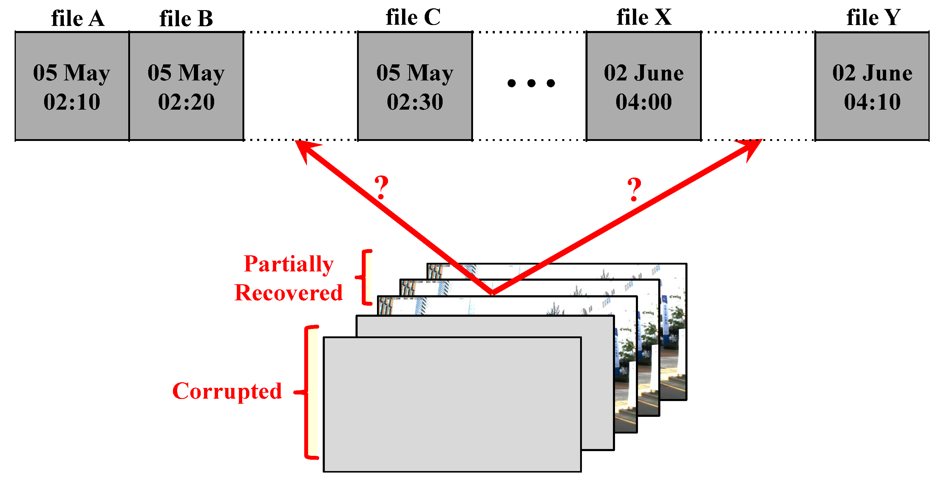
Figure 1. Example of utilizing creation order.
Applsci 09 05522 g001
Figure 2. Structure of the FAT32 file system.
Applsci 09 05522 g002
Figure 3. Structure of directory entry.
Applsci 09 05522 g003
Figure 4. Deletion-backward next fit allocation of Windows FAT32: (a) content clusters when allocating files A-E and next deleting files B and C, (b) content clusters when allocating another file F after (a)
Applsci 09 05522 g004
Figure 5. Example of matching offsets of recovered files with directory entries.
Applsci 09 05522 g005
Figure 6. Example of deleted files without directory entries: (a) seven directory entries in two directory entry clusters and (b) thirty content clusters.
Applsci 09 05522 g006
Figure 7. File allocation traversals of Figure 6b.
Applsci 09 05522 g007
Figure 8. Another example of deleted files without directory entries: (a) twelve directory entries in two directory entry clusters and (b) thirty content clusters
Applsci 09 05522 g008
Figure 9. File allocation traversals of Figure 8b.
Applsci 09 05522 g009
Figure 10. Main graphic user interface of the developed tool.
Applsci 09 05522 g010
Figure 11. Graphic user interface for creation order extraction.
Applsci 09 05522 g011
Table 1. Description of notations.
NotationDescription
?a single hidden event of a deleted file
*uncertain number of continuous hidden events of deleted files
X i file X stored in the directory entry position of ? i
( ) sequential file creation event flow from the beginning of direction entries to their end
[ ] sequential file allocation flow from the beginning of content clusters to their end
Table 2. Summary of experiment results.
No. of CreatedNo. of RecoveredNo. of RecoveredAvg. No. of FoundNo. of Possible
(Deleted) FilesFilesFiles w/o TimeOrdersOrders
50 (12)65 9 5 = 1.8 43
100 (25)129 33 9 3.67 86
150 (37)1713 50 13 3.85 127
Table 3. Accuracy of analyzed creation-time bound.
No. of Created (Deleted) FilesProposed SchemePrevious Method
50 (12)100%60%
100 (25)100%33.3%
150 (37)100%15.4%