Article

Propagation of Cosh-Airy and Cos-Airy Beams in Parabolic Potential

College of Sciences, Zhejiang A&F University, Lin’an 311300, China
*
Author to whom correspondence should be addressed.
Appl. Sci. 2019, 9(24), 5530; https://doi.org/10.3390/app9245530
Submission received: 1 November 2019 / Revised: 5 December 2019 / Accepted: 10 December 2019 / Published: 16 December 2019
(This article belongs to the Section Optics and Lasers)

Abstract

:
The analytical expressions of one-dimensional cosh-Airy and cos-Airy beams in the parabolic potential are derived in the general and the phase transition points. The expression in the phase transition point shows a symmetric Gaussian intensity profile and is independent of any Airy features, which is completely different from that in the general point. The intensity, the center of gravity, and the effective beam size of the cosh-Airy and cos-Airy beams in the parabolic potential are periodic and have the same period. The effects of the transverse displacement, the cosh factor, and the cosine factor on these periodic behaviors are also investigated. The direction of self-acceleration reverses every half-period. The phase transition point is also the inversion point of the intensity distribution, which indicates that the intensity distributions before and after the phase transition point are mirror symmetrical. The periodic behaviors of the normalized intensity, the center of gravity, and the effective beam size of the cosh-Airy and cos-Airy beams in the parabolic potential are attractive and well displayed. The results obtained here may have potential applications in particle manipulation, signal processing, and so on.

1. Introduction

An Airy beam exhibits a unique non-diffracting ability during the beam propagation [1] and can accelerate freely without any external help [2,3]. In the event of obstacles, moreover, the Airy beam displays a self-healing property [4]. The evolution of the Poynting vector [5], the far-field divergent property [6], and the beam propagation factor [7], and the paraxiality [8] of an Airy beam have been investigated. Two methods of geometrical optics [9] and the Wigner distribution function [10] have been used to try to interpret the physical nature of the Airy beams. The propagation of Airy beams through an apertured misaligned paraxial ABCD optical system [11] and the fractional Fourier transform system [12] has been demonstrated previously. In addition, researches on the propagation of Airy beams in free space [13], water [14], turbulent atmosphere [15,16,17], turbulent ocean [18], uniaxial crystal [19], photonic lattice [20,21], saturated medium [22], Kerr medium [23], nonlocal nonlinear media [24,25], medium with parabolic potential [26], chiral materials [27], photorefractive media [28,29], and inhomogeneous medium [30] have been reported. These investigations of Airy-beam propagation in different media have deepened the understanding of Airy beams and contributed to their effective utilization.
The fascinating features of the Airy beam inspire researchers to propose new model beams originating from the Airy beams. In particular, circular Airy beams with autofocusing features [31,32], generalized Airy beams [33,34], and mirror and symmetrical Airy beams [35,36] have been proposed. Here, we focus on two kinds of model beams, namely cosh-Airy and cos-Airy beams. A cosh-Airy beam can be obtained by the superposition of two Airy beams with different decay factors [37], while a cos-Airy beam is the outcome of the superposition of two linearly chirped Airy beams with positive and negative chirped coefficients. Based on the second-order moments, the beam propagation factor of a cosh-Airy beam has been investigated [38]. Although the cosh-Airy beams have similar propagation properties in free space as the Airy beams, they have more manipulation degrees of freedom than the corresponding Airy beams [37]. Also, the self-healing ability of the cosh-Airy beam is higher than that of the corresponding Airy beam [39]. Moreover, propagation properties of the cosh-Airy beam in uniaxial crystals orthogonal to the optical axis are verified to be more abundant than those of the corresponding Airy beam [40]. When a cosh-Airy beam propagates in a quadratic-index inhomogeneous medium, the periodic phase transition occurs [41]. However, to the best of our knowledge, there are very few research reports about cos-Airy beams. In the remainder of this paper, the propagation of cosh-Airy and cos-Airy beams in external parabolic potential is investigated. The cosh-Airy or cos-Airy beam will have two different optical field expressions in the general and the phase transition points. Moreover, the periodic behaviors of the cosh-Airy and cos-Airy beams in the parabolic potential are expected. This research helps to enrich the understanding of the beam characteristics of cosh-Airy and cos-Airy beams.

2. Propagation of Cosh-Airy and Cos-Airy Beams in Parabolic Potential

In the Cartesian coordinate system, the z-axis is taken to be the propagation axis. For simplicity, the cosh-Airy and cos-Airy beams considered here are one-dimensional. The propagation of one-dimensional cosh-Airy and cos-Airy beams obeys the normalized dimensionless linear parabolic equation as follows:
1 2 2 ψ ( x , z ) x 2 + i ψ ( x , z ) z V ( x ) ψ ( x , z ) = 0 ,
where V(x) = L2x2/2 is the parabolic potential, and the parameter L describes the depth of the potential. The variables x and z are the normalized transverse coordinate and the propagation distance, respectively; ψ(x,z) is the envelope of the cosh-Airy and cos-Airy beams. It is known that the propagation of a beam in a parabolic potential is equivalent to the propagation in a quadratic-index waveguide [42,43] as well as in a multilens system [44] and can be described by using the fractional Fourier transform [45,46]. A reformulation of the “separation of variables” scheme in the parabolic equation has been presented [47]. The solution of Equation (1) can be written as [48,49]:
ψ ( x , z ) = f ( x , z ) + [ ψ ˜ ( ξ ) G ˜ ( ξ ) ] exp ( i K ξ ) d ξ ,
with the functions f(x,z) and G ˜ ( ξ ) as well as the parameter K being given by:
f ( x , z ) = K 2 π i x exp ( i b x 2 ) ,
G ˜ ( ξ ) = i π b exp ( i ξ 2 4 b ) ,
K = L x csc ( L z ) .
The parameter b is defined by:
b = L 2 cot ( L z ) ,
where ψ ˜ ( ξ ) is the Fourier transform of ψ ( x , 0 ) , and ψ ( x , 0 ) is the input cosh-Airy or cos-Airy beam. G ˜ ( ξ ) is the Fourier transform of exp ( i b x 2 ) .
First, the input beam is a cosh-Airy beam, which has the form:
ψ ( x , 0 ) = A i ( x x 0 ) exp [ a ( x x 0 ) ] cosh [ γ ( x x 0 ) ] ,
where Ai(·) is the Airy function, a is the decay factor, γ is the cosh factor, and x0 is the transverse displacement. The cosh-Airy beam is the result of the superposition of two Airy beams with different decay factors a + and a . Here, a + and a are defined by a ± = a ± γ . Therefore, γ should be smaller than a. The corresponding Fourier transform of ψ ( x , 0 ) is found to be [50]:
ψ ˜ ( ξ ) = 1 2 exp ( i x 0 ξ + i ξ 3 3 ) [ exp ( a + ξ 2 ) exp ( a + 3 3 i a + 2 ξ ) + exp ( a ξ 2 ) exp ( a 3 3 i a 2 ξ ) ] .
The point z ( m + 1 2 ) π L is referred to as the general point, where m is an arbitrary integer, and the point z = ( m + 1 2 ) π L is called the phase transition point [26]. When z = ( m + 1 2 ) π L , cos(Lz) = 0 and b = 0.
When z ( m + 1 2 ) π L , the general solution of the one-dimensional cosh-Airy beam in the parabolic potential is expressed as:
ψ ( x , z ) = 1 2 K 2 b x exp ( i b x 2 ) { exp ( a + 3 3 ) A i ( K 2 b 1 16 b 2 x 0 + i a + 2 b ) × exp [ ( a + + i 4 b ) ( K 2 b 1 16 b 2 x 0 + i a + 2 b ) ] exp [ i K 2 4 b 1 3 ( a + + i 4 b ) 3 ] + exp ( a 3 3 ) A i ( K 2 b 1 16 b 2 x 0 + i a 2 b ) exp [ ( a + i 4 b ) ( K 2 b 1 16 b 2 x 0 + i a 2 b ) ] × exp [ i K 2 4 b 1 3 ( a + i 4 b ) 3 ] .
In the derivation of the above equation, the following integral formula is used [51]:
exp ( i u 3 3 + i p u 2 + i q u ) d u = 2 π exp [ i p ( 2 p 2 3 q ) ] A i ( q p 2 ) .
When z = ( m + 1 2 ) π L , the one-dimensional cosh-Airy beam in the parabolic potential is described by:
ψ ( x , z ) = 1 2 i s L 2 π exp ( i L x 0 x ) { exp ( a + L 2 x 2 ) exp [ a + 3 3 + i s 3 ( L 3 x 3 3 a + 2 L x ) ] + exp ( a L 2 x 2 ) exp [ a 3 3 + i s 3 ( L 3 x 3 3 a 2 L x ) ] } ,
where s = 1 if m is even, and s = −1 if m is odd. When z = ( m + 1 2 ) π L , the intensity distribution of one-dimensional cosh-Airy beam in the parabolic potential turns out to be:
| ψ ( x , z ) | 2 = L 8 π { exp ( 2 a + L 2 x 2 ) exp ( 2 a + 3 3 ) + exp ( 2 a L 2 x 2 ) exp ( 2 a 3 3 ) + 2 exp [ ( a + + a ) L 2 x 2 ] exp ( a + 3 3 + a 3 3 ) cos [ ( a + 2 a 2 ) L x ] } .
When z = mπ/L, sin(Lz) = 0. In this case, b = and K = . When z mπ/L, Equation (9) reduces to:
ψ ( x , z ) = 1 s A i ( s x x 0 ) exp [ a ( s x x 0 ] cosh [ γ ( s x x 0 ] .
Finally, the input beam is a cos-Airy beam, which is characterized by:
ψ ( x , 0 ) = A i ( x x 0 ) exp [ a ( x x 0 ) ] cos [ β ( x x 0 ) ] ,
where β is the cosine factor. A cos-Airy beam is the result of the superposition of two linearly chirped Airy beams with chirped coefficients β and −β. When z ( m + 1 2 ) π L , the general solution of one-dimensional cos-Airy beam in the parabolic potential is found to be:
ψ ( x , z ) = 1 2 K 2 b x exp ( i b x 2 ) { exp [ ( a + i β ) 3 3 ] A i ( K 2 b 1 16 b 2 β 2 b x 0 + i a 2 b ) × exp [ ( a + i β + i 4 b ) ( K 2 b 1 16 b 2 β 2 b x 0 + i a 2 b ) ] exp [ i K 2 4 b 1 3 ( a + i β + i 4 b ) 3 ] + exp [ ( a i β ) 3 3 ] A i ( K 2 b 1 16 b 2 + β 2 b x 0 + i a 2 b ) exp [ i K 2 4 b 1 3 ( a i β + i 4 b ) 3 ] × exp [ ( a i β + i 4 b ) ( K 2 b 1 16 b 2 + β 2 b x 0 + i a 2 b ) ] .
When z = ( m + 1 2 ) π L , the one-dimensional cos-Airy beam in the parabolic potential turns out to be:
ψ ( x , z ) = 1 2 i s L 2 π exp ( i L x 0 x ) exp ( a L 2 x 2 ) { exp [ ( a + i β ) 3 3 i β L 2 x 2 + i s 3 ( L 3 x 3 3 a 2 L x ) ] + exp [ ( a i β ) 3 3 + i β L 2 x 2 + i s 3 ( L 3 x 3 3 a 2 L x ) ] } .
When z = ( m + 1 2 ) π L , the intensity distribution of the one-dimensional cos-Airy beam in the parabolic potential is expressed as:
| ψ ( x , z ) | 2 = L 4 π exp ( 2 a 3 3 2 a β 2 ) exp ( 2 a L 2 x 2 ) [ 1 + cos ( 2 β L 2 x 2 2 a 2 β + 2 β 3 3 ) ] .
When z = mπ/L, Equation (15) is simplified as:
ψ ( x , z ) = 1 s A i ( s x x 0 ) exp [ a ( s x x 0 ] cos [ β ( s x x 0 ] .
The cosh-Airy and cos-Airy beams propagating in the parabolic potential are periodic and have the same period, T = 2π/L. The optical field expressions of the cosh-Airy beam in the general and the phase transition points are completely different, and so is the cos-Airy beam. The intensity of the cosh-Airy and cos-Airy beams in the phase transition point has a symmetric Gaussian distribution.
The center of gravity of the cosh-Airy and cos-Airy beams in the parabolic potential is defined by [52,53,54]:
X = x | ψ ( x , z ) | 2 d x | ψ ( x , z ) | 2 d x .
The effective beam size of the cosh-Airy and cos-Airy beams in the parabolic potential is given by [52,53,54,55,56,57]:
W x = [ ( x X ) 2 | ψ ( x , z ) | 2 d x | ψ ( x , z ) | 2 d x ] 1 / 2 = [ x 2 | ψ ( x , z ) | 2 d x | ψ ( x , z ) | 2 d x X 2 ] 1 / 2 .
Because of the periodic behavior of the intensity distribution, the center of gravity and the effective beam size are also periodic, and the period is still T = 2π/L.
Note that the fractional Fourier transform is indefinite in a general sense at distances multiple to the half-period [58], therefore, the direct application of the fractional Fourier transform to the input field leads to problems calculating the field at these distances. The algorithm used here is more convenient for calculations at the half-period.

3. Numerical Simulations and Results

First, the difference between cosh-Airy and cos-Airy beams is demonstrated in the input plane, which is shown in Figure 1. A = 0.1 in Figure 1. When γ = β, the cosh-Airy beam has more side lobes than the cos-Airy beam. With increasing cosh factor, the number of the side lobes in the cosh-Airy beam also increases. With increasing cosine factor, however, the number of the side lobes in the cos-Airy beam decreases. Therefore, the cos-Airy beam is significantly different from the cosh-Airy beam.
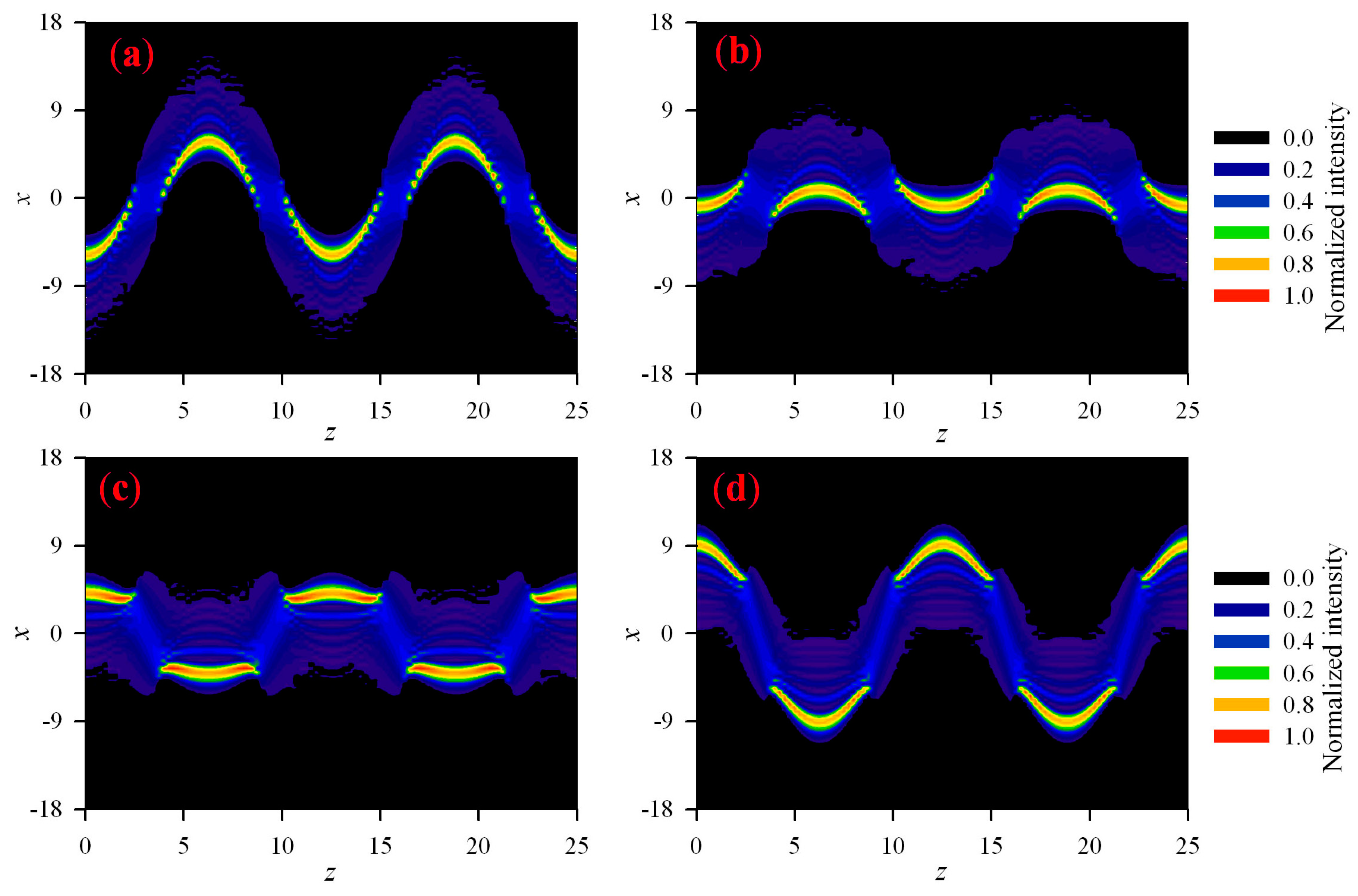
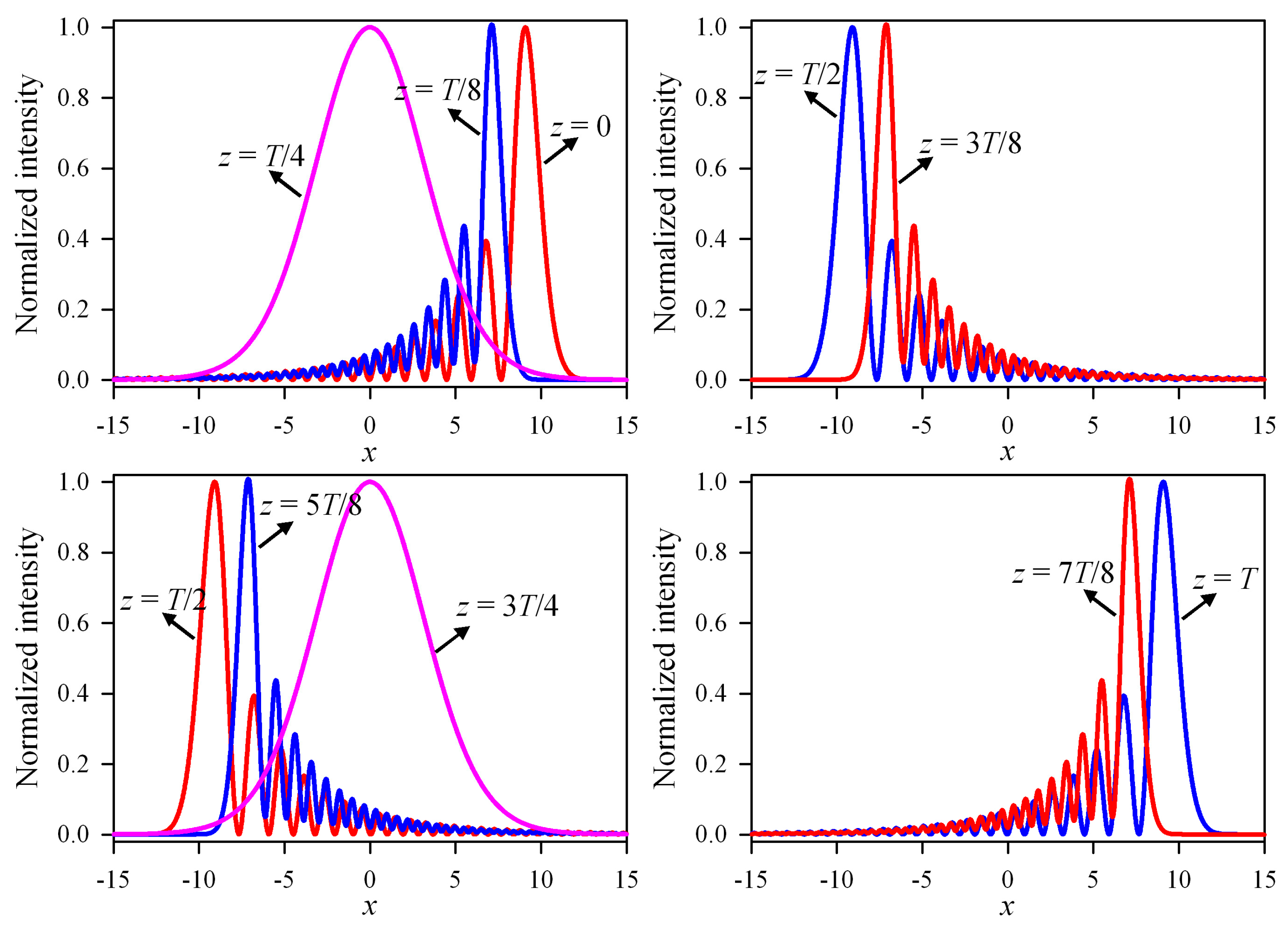
According to the formulae in the above section, the properties of cosh-Airy and cos-Airy beams in the parabolic potential are numerically simulated. In the following calculations, the depth of the potential and the decay factor remain unchanged, and they are set as L = 0.5 and a = 0.1, respectively. Figure 2 represents the contour graph of the normalized intensity of cosh-Airy beams with different transverse displacements in the parabolic potential. γ = 0.04 in Figure 2. The normalized intensity varies periodically upon propagation, and the period is T = 4π. The cosh-Airy beam with the positive transverse displacement accelerates opposite to it with the nonpositive transverse displacement. The curves of the normalized intensity distribution versus the propagation distance are diverse for different transverse displacements. The range of fluctuation of the main lobe in the case of the negative transverse displacement is far larger than that in the case of the contrary transverse displacement. When the transverse displacement disappears, the range of fluctuation of the main lobe is small during the forward-moving process. Figure 3 shows the contour graph of the normalized intensity of cosh-Airy beams with different cosh factors in the parabolic potential. x0 = 10 in Figure 3. When only the cosh factor increases, the number of side lobes adjacent to the main lobe increases significantly. The normalized intensity distribution of the cosh-Airy beam in different observation planes of the parabolic potential is shown in Figure 4, where γ = 0.04 and x0 = 10. When z = T/4 and z = 3T/4, the normalized intensity takes on a symmetric Gaussian distribution, which is caused by the phase transition [26]. The phase transition points z = T/4 and z = 3T/4 are also the inversion points of the intensity distribution. When 0 ≤ z < T/4, the side lobes are located at the left side of the main lobe. When T/4 ≤ z ≤ 3T/4, the side lobes are located at the right side of the main lobe, which is induced by the inversion of the intensity distribution. When 3T/4 < zT, the side lobes are again located at the left side of the main lobe, which is the result of two inversions of the intensity distribution. The blue curve in Figure 4 occurs after the red one. z = T/2 is the inversion point of the accelerating direction. When 0 ≤ zT/2, the cosh-Airy beam accelerates towards the negative direction of the x-axis. It should be emphasized that this direction of self-acceleration depends on the positive transverse displacement. When T/2 ≤ zT, the cosh-Airy beam accelerates towards the positive direction of the x-axis.
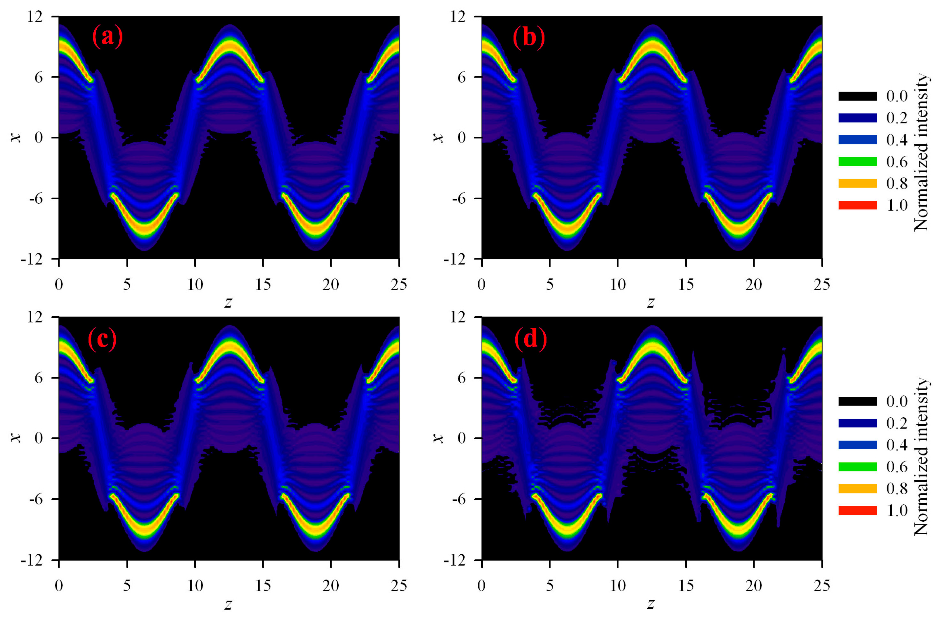
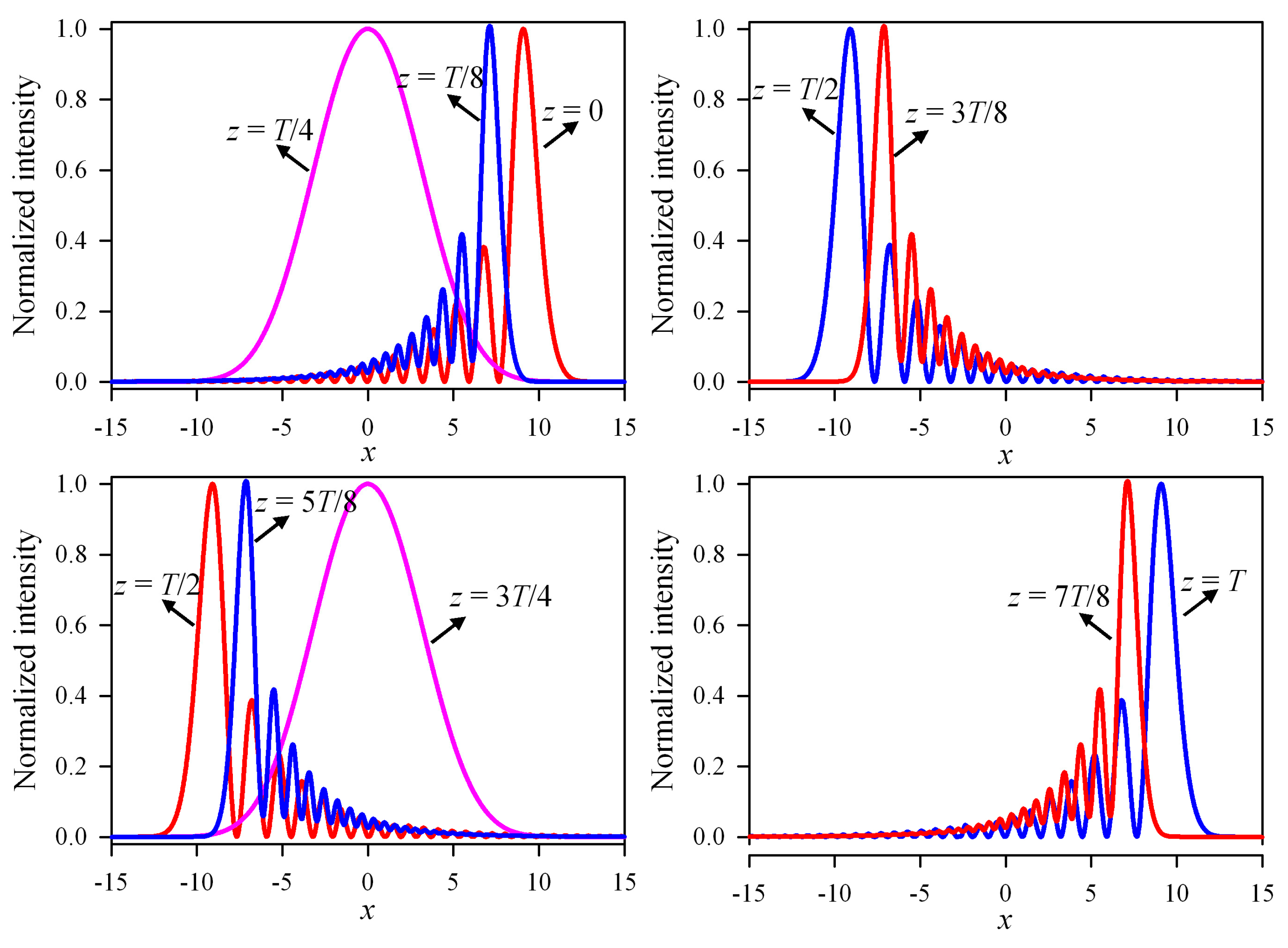
Figure 5 shows the contour graph of the normalized intensity of cos-Airy beams with different transverse displacements in the parabolic potential. β = 0.04 in Figure 5. When the sign of the transverse displacement changes, the direction of the self-acceleration for the cos-Airy beam also changes. Moreover, the range of fluctuation of the main lobe for the cos-Airy beam is more sensitive to the negative transverse displacement than the positive transverse displacement. A contour graph of the normalized intensity of cos-Airy beams with different cosine factors in the parabolic potential is shown in Figure 6, where x0 = 10. When only the cosine factor increases, the number of side lobes decreases. Figure 7 represents the normalized intensity distribution of the cos-Airy beam in different observation planes of the parabolic potential. β = 0.04 and x0 = 10 in Figure 7. Due to the positive transverse displacement, the cos-Airy beam in the first half-period accelerates towards the negative direction of the x-axis. In the latter half-period, however, the cos-Airy beam accelerates towards the positive direction of the x-axis. A Gaussian intensity profile emerges at the phase transition points z = T/4 and z = 3T/4, which are also the inversion points of the intensity distribution. The main difference between Figure 4 and Figure 7 is that the number of side lobes of the cosh-Airy beam is larger than that of the cos-Airy beam. In addition, the Gaussian intensity profile in Figure 3 is wider than that in Figure 7.
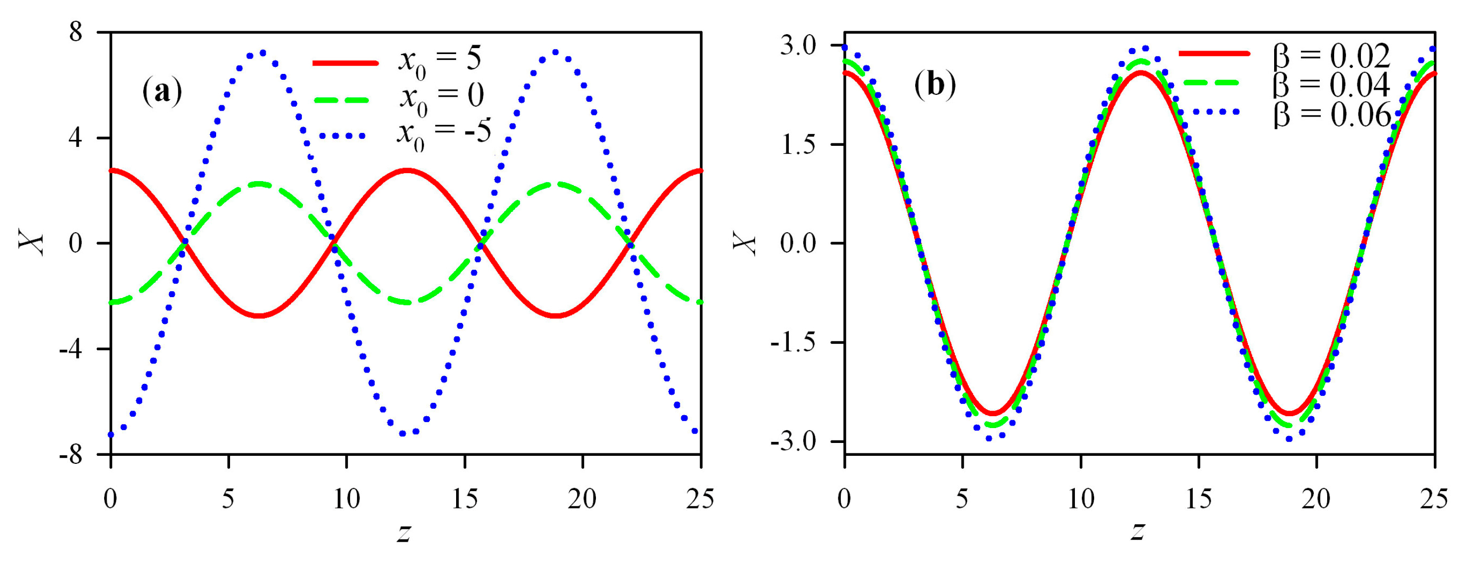
Figure 8 shows the center of gravity of cosh-Airy beams in the parabolic potential. At first, the cosh factor is fixed, for example, γ = 0.04. The effect of the transverse displacement on the center of gravity is investigated here. When the transverse displacement is positive, the center of gravity in the first half-period decreases, while that in the latter half-period increases. When the transverse displacement is negative or zero, the center of gravity in the first half-period increases, while that in the latter half-period decreases. Figure 8a also denotes that the direction of the acceleration in the case of the positive transverse displacement is opposite to that in the case of the nonpositive transverse displacement. No matter what the transverse displacement is, z = T/2 must be the inversion point of the accelerating direction. The amplitude of the center of gravity in the case of the negative transverse displacement is much larger than that in the case of the contrary transverse displacement. Then, the transverse displacement is fixed as x0 = 5, and the effect of the cosh factor on the center of gravity is investigated. The cosh factor only affects the amplitude of the center of gravity. As the cosh factor increases, the amplitude of the center of gravity decreases. The center of gravity of cos-Airy beams in the parabolic potential is shown in Figure 9. The effect of the transverse displacement on the center of gravity of the cos-Airy beam is similar to that of the cosh-Airy beam. The cosine factor only slightly affects the amplitude of the center of gravity. As the cosine factor increases, the amplitude of the center of gravity reduces slowly. The following conclusions can be drawn by comparing Figure 8a and Figure 9a. When the transverse displacement is positive, the amplitude of the center of gravity of the cosh-Airy beam is smaller than that of the cos-Airy beam. When the transverse displacement is nonpositive, the amplitude of the center of gravity of the cosh-Airy beam is larger than that of the cos-Airy beam.
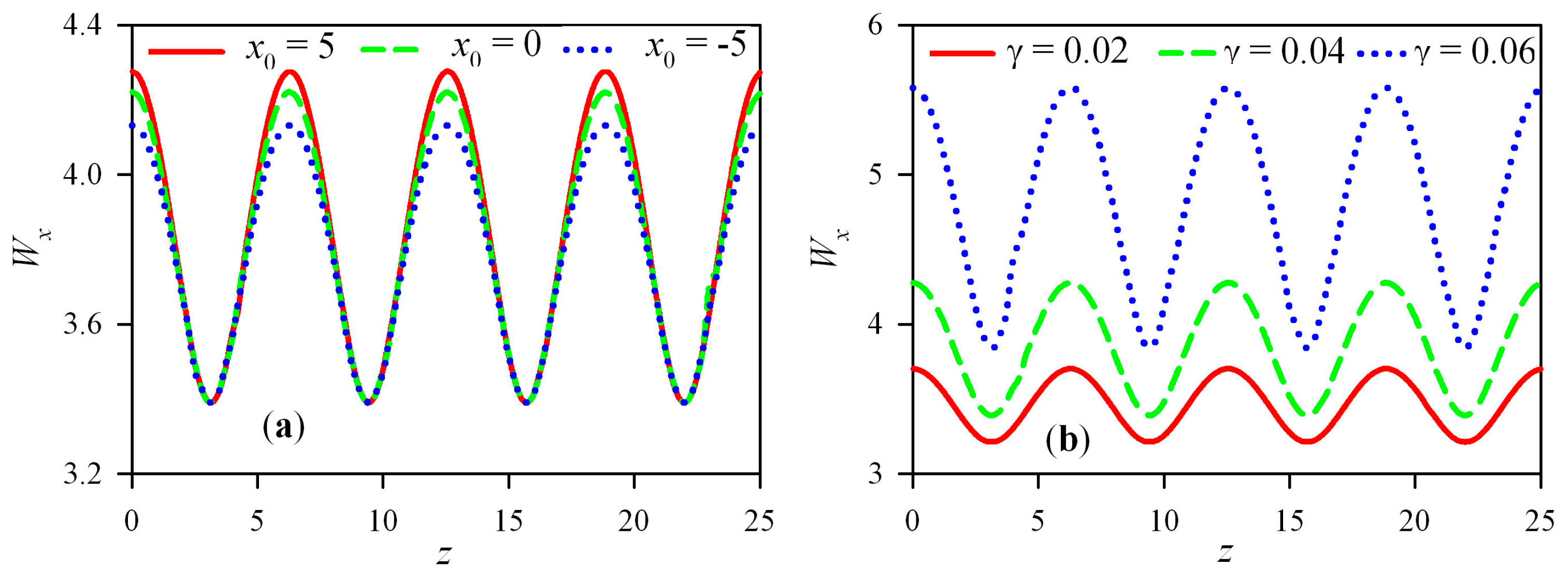
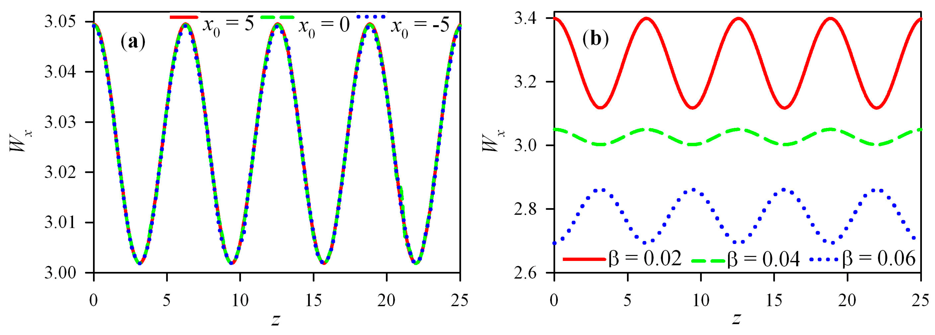
Figure 10 shows the effective beam size of cosh-Airy beams in the parabolic potential. In the first half-period, the effective beam size decreases. In the latter half-period, however, the effective beam size increases. When the transverse displacement is positive, the amplitude of the effective beam size is the largest. When the transverse displacement is negative, the amplitude of the effective beam size is the smallest. As the cosh factor increases, the curve of the effective beam size versus the propagation distance moves upwards, and the amplitude of the effective beam size also increases. The effective beam size increases with the increase of the cosh factor. The effective beam size of cos-Airy beams in the parabolic potential is shown in Figure 11. When β = 0.04, the effect of the transverse displacement on the effective beam size is so small that it can be neglected. As the cosine factor increases, the curve of the effective beam size versus the propagation distance moves downwards, and the effective beam size decreases. Comparison of Figure 10 and Figure 11 denotes that the effective beam size of the cosh-Airy beam is much larger than that of the cos-Airy beam under the same conditions. Moreover, the amplitude of the effective beam size of the cosh-Airy beam is also larger than that of the cos-Airy beam. This is because the number of the side lobes of the cosh-Airy beam is greater than that of the cos-Airy beam.

4. Conclusions

In summary, different analytical expressions of one-dimensional cosh-Airy and cos-Airy beams in the general and the phase transition points of the parabolic potential are derived. The optical fields of the cosh-Airy and cos-Airy beams in the phase transition point have a symmetric Gaussian intensity profile and are independent of the Airy function. The phase transition point z = (2m + 1)T/4 is also the inversion point of the intensity distribution. The intensity, the center of gravity, and the effective beam size of the cosh-Airy and cos-Airy beams in the parabolic potential are periodic and have the same period with T = 2π/L.
The direction of self-acceleration of cosh-Airy and cos-Airy beams with the positive transverse displacement is opposite to those with the nonpositive transverse displacement. Z = (m + 1)T/2 is the inversion point of the direction of self-acceleration. Due to the positive transverse displacement, the cosh-Airy and cos-Airy beams in the first half-period accelerate towards the negative direction of the x-axis. In the latter half-period, however, they accelerate towards the positive direction of the x-axis.
The evolution of the center of gravity in the case of the positive transverse displacements is opposite to that in the case of the nonpositive transverse displacement. When the transverse displacement is positive, the center of gravity in the first half-period decreases, while that in the latter half-period is opposite. The amplitude of the center of gravity in the case of the negative transverse displacement is much larger than that in the case of the contrary transverse displacement. As the cosh factor increases, the amplitude of the center of gravity of the cosh-Airy beam decreases. However, the amplitude of the center of gravity of the cos-Airy beam decreases slowly with the increase of cosine factor.
The effective beam size in the first half-period decreases, while the situation in the latter half-period is just the opposite. The effective beam size of the cosh-Airy beam is sensitive to the transverse displacement. However, the effect of the transverse displacement on the effective beam size of the cos-Airy beam is too small to be detected. As the cosh factor increases, the number of the side lobes of the cosh-Airy beam increases, which results in the increase of the effective beam size. However, the number of the side lobes of the cos-Airy beam decreases with the increase of the cosine factor, whose outcome is the decrease of the effective beam size. Under the same conditions, the effective beam size of the cosh-Airy beam is much larger than that of the cos-Airy beam.
The periodic behaviors of the normalized intensity, the center of gravity, and the effective beam size of the cosh-Airy and cos-Airy beams in the parabolic potential are abundant and well exhibited. The results obtained here may have potential applications in particle manipulation and signal processing, as well as in other fields.

Author Contributions

Y.Z. and G.Z. conceived of and wrote the paper; Y.Z. and Y.X. performed the numerical simulations; X.C. and G.Z. analyzed and evaluated the results.

Funding

This research was supported by the National Natural Science Foundation of China (Grant No. 11974313) and the Open Research Fund of Key Laboratory of Optical Engineering, Chinese Academy Sciences (Grant No. 2017LBC).

Conflicts of Interest

The authors declare no conflict of interest.

References

  1. Berry, M.V.; Balazs, N.L. Nonspreading wave packets. Am. J. Phys. 1979, 47, 264–267. [Google Scholar] [CrossRef]
  2. Siviloglou, G.A.; Brokly, J.; Dogariu, A.; Christodoulides, D.N. Observation of accelerating Airy beam. Phys. Rev. Lett. 2007, 99, 213901. [Google Scholar] [CrossRef] [PubMed]
  3. Siviloglou, G.A.; Christodoulides, D.N. Accelerating finite energy Airy beams. Opt. Lett. 2007, 32, 979–981. [Google Scholar] [CrossRef] [PubMed]
  4. Brokly, J.; Siviloglou, G.A.; Dogariu, A.; Christodoulides, D.N. Self-healing properties of optical Airy beams. Opt. Express 2008, 16, 12880–12891. [Google Scholar] [CrossRef] [PubMed] [Green Version]
  5. Sztul, H.I.; Alfano, R.R. The Poynting vector and angular momentum of Airy beams. Opt. Express 2008, 16, 9411–9416. [Google Scholar] [CrossRef]
  6. Xu, Y.; Zhou, G. The far-field divergent properties of an Airy beam. Opt. Laser Technol. 2012, 44, 1318–1323. [Google Scholar] [CrossRef]
  7. Chen, R.; Ying, C. Beam propagation factor of an Airy beam. J. Opt. 2011, 13, 085704. [Google Scholar] [CrossRef]
  8. Torre, A. Airy beams and paraxiality. J. Opt. 2014, 16, 035702. [Google Scholar] [CrossRef]
  9. Kaganovsky, Y.; Heyman, E. Wave analysis of Airy beams. Opt. Express 2010, 18, 8440–8452. [Google Scholar] [CrossRef]
  10. Chen, R.; Zheng, H.; Dai, C. Wigner distribution function of an Airy beam. J. Opt. Soc. Am. A 2011, 28, 1307–1311. [Google Scholar] [CrossRef]
  11. Wen, W.; Lu, X.; Zhao, C.; Cai, Y. Propagation of Airy beam passing through the misaligned optical system with hard aperture. Opt. Commun. 2014, 313, 350–355. [Google Scholar] [CrossRef]
  12. Zhou, G.; Chen, R.; Chu, X. Fractional Fourier transform of Airy beams. Appl. Phys. B 2012, 109, 549–556. [Google Scholar] [CrossRef]
  13. Siviloglou, G.A.; Brokly, J.; Dogariu, A.; Christodoulides, D.N. Ballistic dynamics of Airy beams. Opt. Lett. 2008, 33, 207–209. [Google Scholar] [CrossRef] [PubMed]
  14. Polynkin, P.; Kolesik, M.; Moloney, J. Filamentation of femtosecond laser Airy beams in water. Phys. Rev. Lett. 2009, 103, 123902. [Google Scholar] [CrossRef] [PubMed] [Green Version]
  15. Chu, X. Evolution of an Airy beam in turbulence. Opt. Lett. 2011, 36, 2701–2703. [Google Scholar] [CrossRef]
  16. Tao, R.; Si, L.; Ma, Y.; Zhou, P.; Liu, Z. Average spreading of finite energy Airy beams in non-Kolmogorov turbulence. Opt. Lasers Eng. 2013, 51, 488–492. [Google Scholar] [CrossRef]
  17. Chen, C.; Yang, H.; Kavehrad, M.; Zhou, Z. Propagation of radial Airy array beams through atmospheric turbulence. Opt. Lasers Eng. 2014, 52, 106–114. [Google Scholar] [CrossRef]
  18. Jin, Y.; Hu, M.; Luo, M.; Luo, Y.; Mi, X.; Zou, C.; Zhou, L.; Shu, C.; Zhu, X.; He, J.; et al. Beam wander of a partially coherent Airy beam in oceanic turbulence. J. Opt. Soc. Am. A 2018, 35, 1457–1464. [Google Scholar] [CrossRef]
  19. Zhou, G.; Chen, R.; Chu, X. Propagation of Airy beams in uniaxial crystals orthogonal to the optical axis. Opt. Express 2012, 20, 2196–2205. [Google Scholar] [CrossRef]
  20. Xiao, F.; Li, B.; Wang, M.; Zhu, W.; Zhang, P.; Liu, S.; Premaratne, M.; Zhao, J. Optical Bloch oscillations of an Airy beam in a photonic lattice with a linear transverse index gradient. Opt. Express 2014, 22, 22763–22770. [Google Scholar] [CrossRef]
  21. Diebel, F.; Bokic, B.; Boguslawski, M.; Piper, A.; Timotijevic, D.; Jovic, D.; Denz, C. Control of Airy-beam self-acceleration by photonic lattices. Phys. Rev. A 2014, 90, 033802. [Google Scholar] [CrossRef] [Green Version]
  22. Chen, R.; Chew, K.; Zhao, T.; Li, P.; Li, C. Evolution of an Airy beam in a saturated medium. Laser Phys. 2014, 24, 115402. [Google Scholar] [CrossRef]
  23. Chen, R.; Yin, C.; Chu, X.; Wang, H. Effect of Kerr nonlinearity on an Airy beam. Phys. Rev. A 2010, 82, 043832. [Google Scholar] [CrossRef]
  24. Zhou, G.; Chen, R.; Ru, G. Propagation of an Airy beam in a strongly nonlocal nonlinear media. Laser Phys. Lett. 2014, 11, 105001. [Google Scholar] [CrossRef]
  25. Huang, S.; Shi, X.; Bai, Y.; Fu, X. Multi-solitons shedding from truncated Airy beam in nonlocal nonlinear media. IEEE Photonics Technol. Lett. 2016, 28, 1621–1624. [Google Scholar] [CrossRef]
  26. Zhang, Y.; Belić, M.R.; Zhang, L.; Zhong, W.; Zhu, D.; Wang, R.; Zhang, Y. Periodic inversion and phase transition of finite energy Airy beams in a medium with parabolic potential. Opt. Express 2015, 23, 10467–10480. [Google Scholar] [CrossRef]
  27. Lin, H.; Pu, J. Propagation of Airy beams from right-handed material to left-handed material. Chin. Phys. B 2012, 21, 054201. [Google Scholar] [CrossRef]
  28. Jia, S.; Lee, J.; Fleischer, J.W.; Siviloglou, G.A.; Christodoulides, D.N. Diffusion-trapped Airy beams in photorefractive media. Phys. Rev. Lett. 2010, 104, 253904. [Google Scholar] [CrossRef]
  29. Zhang, M.; Zhang, T.; Huo, G.; Hui, Z.; Duan, Z.; Zha, X. Temporal analysis of Airy beam propagation in photorefractive media. Commun. Nonlinear Sci. 2019, 76, 45–50. [Google Scholar] [CrossRef]
  30. Li, H.; Tang, M.; Wang, J.; Cao, J.; Li, X. Spin hall effect of Airy beam in inhomogeneous medium. Appl. Phys. B 2019, 125, 51. [Google Scholar] [CrossRef]
  31. Efremidis, N.K.; Christodoulides, D.N. Abruptly autofocusing waves. Opt. Lett. 2010, 35, 4045–4047. [Google Scholar] [CrossRef]
  32. Porfirev, A.P.; Khonina, S.N. Generation of azimuthally modulated circular superlinear Airy beams. J. Opt. Soc. Am. B 2017, 34, 2544–2549. [Google Scholar] [CrossRef]
  33. Belafhal, A.; Ez-Zariy, L.; Hennani, S.; Nebdi, H. Theoretical introduction and generation method of a novel nondiffracting waves: Olver beams. Opt. Photon. J. 2015, 5, 234–246. [Google Scholar] [CrossRef] [Green Version]
  34. Khonina, S.N.; Ustinov, A.V. Fractional Airy beams. J. Opt. Soc. Am. A 2017, 34, 1991–1999. [Google Scholar] [CrossRef]
  35. Khonina, S.N. Specular and vortical Airy beams. Opt. Commun. 2011, 284, 4263–4271. [Google Scholar] [CrossRef]
  36. Vaveliuk, P.; Lencina, A.; Rodrigo, J.A.; Matos, O.M. Symmetric Airy beams. Opt. Lett. 2014, 39, 2370–2373. [Google Scholar] [CrossRef] [Green Version]
  37. Li, H.; Wang, J.; Tang, M.; Li, X. Propagation properties of cosh-Airy beams. J. Mod. Opt. 2018, 65, 314–320. [Google Scholar] [CrossRef]
  38. Zhou, Y.; Xu, Y.; Zhou, G. Beam propagation factor of a cosh-Airy beam. Appl. Sci. 2019, 9, 1817. [Google Scholar] [CrossRef] [Green Version]
  39. Zhou, G.; Chu, X.; Chen, R.; Zhou, Y. Self-healing properties of cosh-Airy beams. Laser Phys. 2019, 29, 025001. [Google Scholar] [CrossRef]
  40. Zhou, G.; Chen, R.; Chu, X. Propagation of cosh-Airy beams in uniaxial crystals orthogonal to the optical axis. Opt. Laser Technol. 2019, 116, 72–82. [Google Scholar] [CrossRef]
  41. Li, H.; Wang, J.; Tang, M.; Cao, J.; Li, X. Phase transition of cosh-Airy beams in inhomogeneous media. Opt. Commun. 2018, 427, 147–151. [Google Scholar] [CrossRef]
  42. Feit, M.D.; Fleck, J.A. Light propagation in graded-index optical fibers. Appl. Opt. 1978, 17, 3990–3998. [Google Scholar] [CrossRef] [PubMed]
  43. Mendlovic, D.; Ozaktas, H.M.; Lohmann, A.W. Graded-index fibers, Wigner-distribution functions, and the fractional Fourier transform. Appl. Opt. 1994, 33, 6188–6193. [Google Scholar] [CrossRef] [PubMed] [Green Version]
  44. Dorsch, R.G.; Lohmann, A.W. Fractional Fourier transform used for a lens-design problem. Appl. Opt. 1995, 34, 4111–4112. [Google Scholar] [CrossRef] [PubMed]
  45. Namias, V. The fractional order Fourier transform and its application to quantum mechanics. IMA J. Appl. Math. 1980, 25, 241–265. [Google Scholar] [CrossRef]
  46. Mendlovic, D.; Ozaktas, H.M. Fractional Fourier transforms and their optical implementation: I. J. Opt. Soc. Am. A 1993, 10, 1875–1881. [Google Scholar] [CrossRef] [Green Version]
  47. Kazakov, A.Y. “Separation of variables” in the model problems of the diffraction theory. A formal scheme. J. Math. Sci. 2019, 243, 715–725. [Google Scholar] [CrossRef]
  48. Agarwal, G.; Simon, R. A simple realization of fractional Fourier transform and relation to harmonic oscillator Green’s function. Opt. Commun. 1994, 110, 23–26. [Google Scholar] [CrossRef]
  49. Bernardini, C.; Gori, F.; Santarsiero, M. Converting states of a particle under uniform or elastic forces into free particle states. Eur. J. Phys. 1995, 16, 58–62. [Google Scholar] [CrossRef]
  50. Gradshteyn, I.S.; Ryzhik, I.M. Table of Integrals, Series, and Products; Academic Press: New York, NY, USA, 1980. [Google Scholar]
  51. Vallée, O.; Manuel, S. Airy Functions and Applications to Physics; Imperial College Press: London, UK, 2010. [Google Scholar]
  52. Hodgson, N.; Weber, H. Laser Resonators and Beam Propagation; Springer Press: New York, NY, USA, 2005. [Google Scholar]
  53. Zhou, G. Generalized beam propagation factors of truncated partially coherent cosine-Gaussian and cosh-Gaussian beams. Opt. Laser Technol. 2010, 42, 489–496. [Google Scholar] [CrossRef]
  54. Zhou, G.; Ji, Z.; Ru, G. Complete analytical expression of Lorentz-Hermite-Gauss laser beams. Lasers Eng. 2018, 40, 127–147. [Google Scholar]
  55. Nemes, G.; Serna, J. Laser beam characterization with use of second order moments: An overview. OSA TOPS 1998, 17, 200–207. [Google Scholar]
  56. Zhou, G. Far field structural properties of a Gaussian vortex beam. Lasers Eng. 2013, 26, 1–17. [Google Scholar] [CrossRef]
  57. Ni, Y.; Ji, Z.; Ru, G.; Zhou, G. Propagation properties of controllable dark hollow laser beams in uniaxial crystals along the optical axis. Lasers Eng. 2017, 38, 283–305. [Google Scholar]
  58. Khonina, S.N.; Striletz, A.S.; Kovalev, A.A.; Kotlyar, V.V. Propagation of laser vortex beams in a parabolic optical fiber. Proc. SPIE 2010, 7523, 75230B. [Google Scholar]
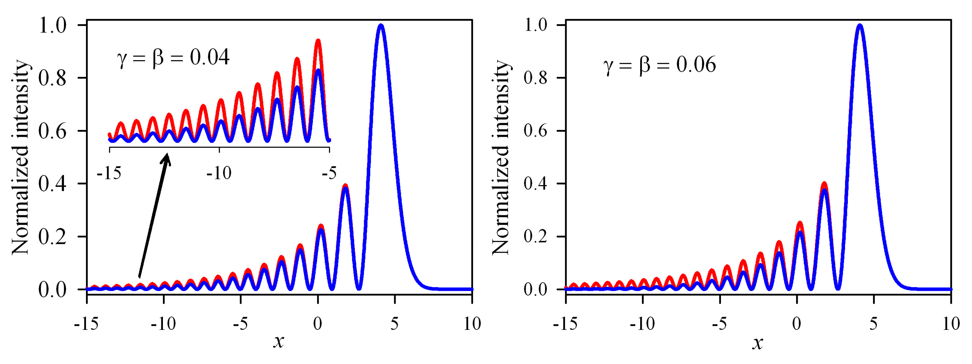
Figure 1. Normalized intensity distribution of cosh-Airy (the red curve) and cos-Airy (the blue curve) beams with x0 = 5 in the input plane.
Applsci 09 05530 g001
Figure 2. Contour graph of the normalized intensity of cosh-Airy beams with different transverse displacements in the parabolic potential. γ = 0.04. (a) x0 = −5. (b) x0 = 0. (c) x0 = 5. (d) x0 = 10.
Applsci 09 05530 g002
Figure 3. Contour graph of the normalized intensity of cosh-Airy beams with different cosh factors in the parabolic potential. x0 = 10. (a) γ = 0.02. (b) γ = 0.04. (c) γ = 0.06. (d) γ = 0.08.
Applsci 09 05530 g003
Figure 4. Normalized intensity distribution of the cosh-Airy beam in different observation planes of the parabolic potential. γ = 0.04 and x0 = 10.
Applsci 09 05530 g004
Figure 5. Contour graph of the normalized intensity of cos-Airy beams with different transverse displacements in the parabolic potential. β = 0.04. (a) x0 = −5. (b) x0 = 0. (c) x0 = 5. (d) x0 = 10.
Applsci 09 05530 g005
Figure 6. Contour graph of the normalized intensity of cos-Airy beams with different cosine factors in the parabolic potential. x0 = 10. (a) β = 0.02. (b) β = 0.04. (c) β = 0.06. (d) β = 0.08.
Applsci 09 05530 g006
Figure 7. Normalized intensity distribution of the cos-Airy beam in different observation planes of the parabolic potential. β = 0.04 and x0 = 10.
Applsci 09 05530 g007
Figure 8. The center of gravity of cosh-Airy beams in the parabolic potential. (a) γ = 0.04. (b) x0 = 5.
Applsci 09 05530 g008
Figure 9. The center of gravity of cos-Airy beams in the parabolic potential. (a) β = 0.04. (b) x0 = 5.
Applsci 09 05530 g009
Figure 10. The effective beam size of cosh-Airy beams in the parabolic potential. (a) γ = 0.04. (b) x0 = 5.
Applsci 09 05530 g010
Figure 11. The effective beam size of cos-Airy beams in the parabolic potential. (a) β = 0.04. (b) x0 = 5.
Applsci 09 05530 g011