Article

Miniaturized Optical Encoder with Micro Structured Encoder Disc

1
Hahn-Schickard, 70569 Stuttgart, Germany
2
Institut für Mikroelektronik Stuttgart, 70569 Stuttgart, Germany
3
Institute for Micro Integration (IFM), University of Stuttgart, 70569 Stuttgart, Germany
*
Author to whom correspondence should be addressed.
Appl. Sci. 2019, 9(3), 452; https://doi.org/10.3390/app9030452
Submission received: 30 November 2018 / Revised: 22 January 2019 / Accepted: 23 January 2019 / Published: 29 January 2019
(This article belongs to the Special Issue Micro/Nano Manufacturing)

Abstract

:
A novel optical incremental and absolute encoder based on an optical application-specific integrated circuit (opto-ASIC) and an encoder disc carrying micro manufactured structures is presented. The physical basis of the encoder is the diffraction of light using a reflective phase grating. The opto-ASIC contains a ring of photodiodes that represents the encryption of the encoder. It also includes the analog signal conditioning, the signal acquisition, and the control of a light source, as well as the digital position processing. The development and fabrication of the opto-ASIC is also described in this work. A laser diode was assembled in the center on top of the opto-ASIC, together with a micro manufactured polymer lens. The latter was fabricated using ultra-precision machining. The encoder disc was fabricated using micro injection molding and contains micro structures forming a blazed grating. This way, a 10-bit optical encoder with a form factor of only 1 cm3 was realized and tested successfully.

1. Introduction

Rotary encoders are widely used to detect the rotation angle of motors and gear shafts. State-of-the-art encoders mostly operate on potentiometric, capacitive, magnetic, or optical principles [1]. Magnetic and optical encoders are most common in use with an annual growth rate of 11%, whereby the optical technology dominates the global industrial encoder market. The market of encoders is segmented into automotive (35%), electronics (28%), machines (21%), and others (16%) [2]. It is expected that, by 2021, the global market size of the encoders will reach $760 million [3].
The common approach of magnetic encoders is to use a magnetic rotor and to detect the position of the rotor with a hall sensor. In contrast, the common structure of optical encoders is to use a chrome structured encoder disc made of glass. The position of the rotor is then detected with a light barrier. Both operating principles are shown in Figure 1. The advantages of magnetic encoders are their high robustness and low fabrication costs, whereas optical encoders show high accuracy and high dynamics. A distinction is made between incremental and absolute encoders. While absolute encoders deliver the angular position immediately after switching on the encoder, incremental encoders firstly need a reference run. Otherwise only relative position measurement is possible. This article deals solely with absolute optical encoders. As a result of the extensive topic which comprises optical design, injection molding, ultra-precision machining, application-specific integrated circuit (ASIC) design and micro assembly, not all details can be presented in this article.
Absolute encoder discs contain the angle information typically as a Gray code pattern, which is read out in accordance with a transmission principle. Every position of an absolute encoder is unique. Figure 2a shows the Gray code pattern for an encoder disc with n = 6 tracks (6-bit resolution) and its optical path. This results in 2n = 64 positions per revolution of the encoder disc. This means that, for a higher resolution, there are more tracks necessary. The tracks consist of opaque and transparent parts. Each track is read out optically with a light barrier as shown in Figure 2b. This means that, for a resolution of n bits, there are n tracks with n light barriers necessary. As a result, the dimensions of optical encoders increase with their resolution, and the effort for assembling increases due to elaborate alignment processes between the optical device and the encoder disc [4].
However, the smaller the encoder is, the lower its resolution and the higher its costs will be, because, on small discs, there is less space for the Gray code patterns and the associated light barriers; additionally, the expense for the assembly increases due to the complicated fine mechanical–optical system [5,6]. For example, an optical high-end encoder with a diameter of 13 mm delivers a resolution of only 256 increments, while the costs are on the order of several hundreds of euros [7,8]. Also, the accuracy decreases with smaller diameters because the influence of the angular error due to eccentricity between encoder disc and encoder shaft increases for smaller diameters of the encoder disc [9]. Table 1 shows two examples of high-end state-of-the-art-encoders with comparatively very small dimensions. Especially for small devices such as finger prostheses, miniaturized drives, or miniaturized robots, the need for small encoders with high resolution is obvious. Therefore, the motivation of this work was to develop a small absolute optical low-cost encoder with a significant higher resolution, such as state-of-the-art encoders with comparable small dimensions.
To overcome the physical limitations for optical state-of-the-art encoders, a new approach was developed using a reflective blazed grating as an encoder disc and a specific photo detector with a circular array of photodiodes. In this way, the diameter of the encoder disc was no longer the limitation for the resolution because, on the encoder disc, there are no longer any Gray code patterns. In this way, a centric optical scanning of the encoder disc was possible. This achieved a higher integration density because the optical device could also be arranged centrically. Of course, the circular array of photodiodes was now the limitation factor. By comparison, state-of-the-art encoders need an eccentric arrangement of the optical device and, therefore, more construction space. With this novel approach, an optical encoder with a resolution of 1024 increments within only 1 cm3 was developed. A demonstrator was built and tested successfully.
The main advances of the proposed encoder are the small dimensions with a comparatively high resolution and an adjustment-free assembling of the encoder disc. Another advance is the manufacturing method of the encoder disc itself. While traditional optical encoders with high resolution need expensive encoder discs made of glass with chromium patterns and an additional adjustment process of the encoder disc, the proposed encoder needs only an injection-molded encoder disc with a simple blazed grating. The optical set-up is also relatively simple because the optical path is in a reflection order and there is no additional adjustment process necessary. A further advantage is the modular design concept. The same optical module and grating can be used for different encoder diameters. In summary, this results in a low-cost encoder with high resolution and small dimensions.

2. A New Approach for Optical Encoders

2.1. Main Principle of the Encoder

The physical basis of the optical encoder was the diffraction of light using a reflective phase grating. The approach was to use a reflective phase grating as an encoder disc for an optical encoder. Figure 3 shows the mechanism of diffraction schematically. After reflection of the light at the phase grating, destructive and constructive interference occurs because of the path difference Δ of the light, which is caused by the grating. If Δ is equal to λ, constructive interference occurs and, if Δ is equal to 0.5λ, destructive interference occurs.
The relationship between the grating constant and the angle of diffraction is described by the so-called grating equation as follows:
s i n   α e s i n   α m =   m λ g ,
where αe is the angle of the incident light and αm is the angle of the diffracted light. With a given wavelength λ and grating constant g, the angle of the diffracted light can be calculated for each diffraction order m (m = 0, ±1, ±2, …) using this equation.
The concept for the optical encoder was to use a light source on top of a photo detector that transmits light through a lens to the encoder disc. The disc contains micro structures forming the grating. The light is then diffracted at the encoder disc and reaches the photo detector. While laminar gratings result in two beams of equal intensity with the zero order of the beam being reflected into the light source [10,11,12,13,14,15], a blazed grating diffracts two beams of different intensities. This is due to the fact, that the zero order is diffracted into the +1st order beam.
When the disc rotates, the two diffracted light spots also rotate on the photo detector. In this way, it is possible to detect the rotational movement of the encoder disc. This circulation was detected by a ring of photodiodes on an opto-ASIC. While the beams were of different intensity, an unambiguous assignment of the disc angle over 360° was accomplished. Figure 4 shows the functional principle of the optical encoder and the underlying concept for the arrangement of the individual components [16,17].
To detect the rotational angle of the diffracted beams on the photodiode ring, different concepts for the photodiodes were investigated and designed. The first concept consists of a segmented arrangement of photodiodes as shown in Figure 5a. This approach leads to a simple focusing lens to form circular spots, but requires 1024 photodiodes on the opto-ASIC for an encoder resolution of 10 bits. Thus, the signal processing unit had to be designed to read out 1024 photodiodes.
The second concept consists of a Gray code arrangement of the photodiodes as shown in Figure 5b. This approach requires a number of tracks of photodiodes of significantly bigger size, but a more complex lens, as the diffracted beam has to be additionally expanded in the radial direction to illuminate all photodiode tracks. For 10-bit resolution, 10 tracks of photodiodes with the most significant bit (MSB) on the inner track and the least significant bit (LSB) on the outer track are required.
By using photodiodes for the dark and bright parts of the Gray code, differential signals can be obtained leading to a higher signal-to-noise ratio (SNR) and offset compensation. An additional outer track with an offset by half a diode was provided. Hence, the interpolation of the expected sin/cos signals from the last two outer LSB tracks was possible, allowing increased relative resolution of the rotational angle between the two photodiodes.
The two lenses (one for the segmented and another one for the Gray code detector) were designed by ray-tracing, using the optical design software OSLO® (Optics Software for Layout and Optimization). Because of the two different layouts of the photo detector, two different designs for the optical path were necessary. Figure 6 shows the optical path for both versions. For the first photo detector with the segmented photodiodes, a centric lens to focus the light onto the photo detector was needed. For the second photo detector with Gray code arrangement of the photodiodes, an additional lens was necessary to expand the diffracted spot in the radial direction and to illuminate all photodiode tracks. This led of course to a more complex optical path.
The main advantage of the novel approach for optical encoders is that a lateral displacement or eccentricity of the disc does not influence the optical path. The encoder disc can be illuminated in its center, as well as on its outer diameter. Thus, hollow shaft encoders can be realized as well.
A further advantage is that the functional principle of the encoder can be used to develop a modular design concept for optical encoders. When the design for the optical module is defined, the same optical module can also be used for different encoder diameters. Even the grating remains unchanged. Only the diameter of the disc needs to be adapted. A further aspect of this concept is the small dimensions with a comparatively high resolution. Thus, a low-cost encoder is possible with this novel approach.

2.2. Proof of Principle

To prove the optical principle, a first set-up was realized using a High Dynamic Range complementary metal-oxide semiconductor (CMOS) (HDRC®) image sensor and a glass lid on top of it. Figure 7 shows the demonstrator for the proof of principle. To mount the laser diode with a lens holder on it, the lid was processed with traces made of Cr/Au using a laser-cut mask and physical vapor deposition (PVD). The laser diode and the lens were assembled directly on the glass lid. The glass lid itself was assembled on top of the image sensor. The grating with a grating constant of 1.7 µm was attached at the rotatable shaft with a specific mounting. After joining the housing with the shaft and the image sensor, the characteristics of the spots could be observed using the image sensor.
For fabrication of the lenses, ultra-precision machining (UPM) was used. This allowed fabricating custom lenses in polymethyl methacrylate (PMMA) using a diamond tool. In this way, a dimensional accuracy of 1–2 µm and a surface roughness of 10 nm were achieved for the lens. A commercially available blazed grating [18] was used and integrated into a ball-bearing encoder chassis that was mounted on top of the image sensor.
With this equipment, it was possible to visualize and to investigate the spot shape of the two concepts with two different lenses. Measurements of this arrangement with the two lenses were performed—the first one for the segmented photo detector with two elliptical spots with different intensity, and the second one for the Gray code pattern. With the additional toroid lens, it was possible to expand the diffracted beam in the radial direction to realize two linear spots. The measured spot shapes are shown in Figure 8a,b for both lenses. Figure 8c shows the relative intensity of the spots from the second lens.
Analysis of the images obtained using the log-scale HDRC® image sensor showed good agreement within the theoretically calculated optical laser spots. Figure 9a shows the simulated spot for the segmented photo detector, while Figure 9b shows the spot for the Gray code detector. For the simulation, the optical ray-tracing software OSLO® was used. For the light source, a Gaussian beam profile was assumed. By turning the encoder shaft, the laser spots of the diffracted beams circulated around the laser diode. That means that both lenses were suitable for the optical path with each characteristic spot shape.

2.3. Photodiode Readout Circuits of the Opto-ASIC

In order to convert the photodiode current into voltage, transimpedance amplifiers were integrated inside the opto-ASIC. The photodiodes of the Gray code structure were read out in a differential mode, as can be seen in Figure 10. Therefore, all dark photodiodes (PDdark) of one ring were shorted, together as well as the bright photodiodes (PDbright). The output voltage of the transimpedance amplifiers of those two pairs was compared using a comparator and translated into a logical signal at once. The 10 bit positions of the spot were achieved by implementing ten similar circuit structures and were read out in parallel. A following digital block calculated the spot location and output the result via a serial interface.
The simplified readout circuit of the segmented photodiode structure can be seen in Figure 11. In comparison to the Gray code structure, each of the 1024 photodiodes had to be read out separately to get the spot position. To overcome the limited chip array, speed, and the power consumption, 128 segmented photodiodes were connected to one read-out circuit consequently via a multiplexer structure, followed by a transimpedance amplifier and a comparator for a sequential selection. This yielded eight independent read-out blocks, which could be controlled and read out in parallel by the digital block. The threshold reference voltages of the comparator could be separately adjusted for each block, also allowing a compensation of the photodiode process variation. The comparator decisions of all eight blocks were connected to a digital logic block, which calculated the spot position.

2.4. Design Concept of the Demonstrator for the Miniaturized Optical Encoder

Parallel to the development of the opto-ASIC, the demonstrator for a miniaturized optical encoder was designed. Figure 12 shows a cross-section of the demonstrator.
The main emphasis was the miniaturized assembly and the development of the assembling concept based on chip-on-board technology. The dimensions of the demonstrator were about 10 mm in length and width, and 10 mm in height, measured without the connector and without the encoder shaft.
The assembly concept for the optical module was a combination of chip-on-board and chip-on-chip technology. Figure 13 shows the assembling concept of the demonstrator. Firstly, the opto-ASIC was assembled onto a board. After this, the laser diode was assembled directly onto the opto-ASIC. It was important to assemble the laser diode concentric to the ring of photodiodes, as an eccentric arrangement would lead to an incorrectly measured angle during operation. After wire bonding of the opto-ASIC and laser diode, the lens was assembled on top of the opto-ASIC. Finally, the assembly of the housing, the encoder disc, the bearing, and the encoder shaft followed to complete the encoder.

3. Results

3.1. Opto-ASIC

Both encoding concepts of the photodiodes have their pros and cons. While the segmented concept has a simple optical path but complex signal processing, the concept with the Gray code structure has simple signal processing but a more complex optical path. Both opto-ASICs with the two different photodiode structures are shown in Figure 14.
Opto-ASICs for both variants were designed and fabricated using a mask programmable process. This approach allowed for a pre-fabricated, so-called master wafer containing analog and digital structures. The final wiring of its function was realized by the last two metal layers. Thus, a batch of master wafers was processed, and the different circuit variants were personalized by the metallization layers. In addition to the photodiode rings, the opto-ASIC includes transimpedance amplifiers, programmable comparators for digitizing the signals [19], and the logic to analyze the position of the spots on the opto-ASIC. It has a total size of 4.7 × 4.7 × 0.3 mm3 and detects and tracks the spot position. It is directly mounted on a printed circuit board (PCB) with necessary passives for the system.

3.2. Light Source

For the light source, a vertical-cavity surface-emitting laser (VCSEL) with a feed size of 200 µm and a wavelength of 850 nm was chosen, because this wavelength fit best to the grating. The laser diode was mounted on top of the opto-ASIC by gluing and bonding it to the surface of the chip. The laser diode cavity was placed in the center of the photodiode rings (see Figure 15), whereby the opto-ASIC itself was mounted onto a PCB.
Due to the temperature dependence of the laser, the light intensity was controlled by the opto-ASIC using the signal from the photodiodes in a closed-loop fashion. In this manner, a constant intensity of the laser light and, therefore, stable photodiode signals over temperature and time were guaranteed.

3.3. Micro Lens

For the miniaturized optical encoder, an additional micro lens was designed to fit on top of the opto-ASIC, focusing the light to the disc with a spot size of ~40 µm. It had a total diameter of 4.2 mm, while the diameter of the lens itself was only 1 mm. For the Gray code encoder, an additional toroid lens was included to expand the diffracted beam in the radial direction. The lenses were fabricated in PMMA using UPM and glued on top of the opto-ASIC. Figure 16 shows the assembled lens on top of the opto-ASIC.

3.4. Manufacturing of the Micro Structured Encoder Discs

Because of the miniaturized dimensions of the optical encoder, small encoder discs were necessary. The encoder discs were fabricated using precision injection molding of polycarbonate (Makrolon® OD2015). Therefore, an injection mold was constructed. Figure 17 shows the design concept of the injection mold. The cavity of the encoder disc was located at the inner position of the mold and the marked stamper carrying the grating was necessary to form the micro structures of the blazed grating into the surface of the disc. The commercially available blazed grating used for the first demonstrator for proof of principle of the encoder was used to fabricate nickel stampers with a thickness of 0.3 mm using the galvanic reproduction technique. The nickel stamper was clamped inside the cavity of the injection mold. This way, encoder discs were fabricated, while this process allows for a scalable production at low manufacturing costs.
As the blazed grating was a continuous shape, an alignment of the stamper inside the cavity was not required. Figure 18 shows the molded encoder disc directly after its fabrication. The picture shows the encoder disc with the sprue still present to the left and the right of the encoder disc. To create a reflective surface, the discs were coated with gold using a PVD process. The quality of the gold depended on the sputtering target. The used target had a purity level of 99.999%. That means that the gold layer had a purity level slightly lower, because, during the sputtering process, there is the possibility that foreign atoms are incorporated into the gold crystal lattice. The gold layer had a thickness of 50 nm.
With a total diameter of 4.2 mm, a height of 1.2 mm, and a grating constant of 1.7 µm, the encoder discs can be duplicated economically. The discs were assembled to the shaft of the encoder using a suitable adhesive. The size of the disc toward smaller diameters is only limited for practical reasons such as handling. The challenge is probably to find a feasible handling concept for very small discs. However, bigger discs are also possible with this concept, such as hollow shaft encoders.

4. Characterization of the Miniaturized Encoder

With the fabricated components, the demonstrator samples for the novel optical encoders were assembled and characterized. Figure 19 shows the completely assembled demonstrator for the miniaturized optical encoder. Thereby, the PCB acts also as the connector of the encoder. The part of the PCB which is taller than the encoder chassis is suitable for a conventional board connector [20].
For characterization, a customized test bench for encoders was used. Figure 20 presents the signal of bit 6 of the Gray code encoder as an example over one revolution (360°). Because of the layout of the photodiodes, it was possible to generate differential signals. This automatically led to more stable signals with twice the amplitude. As shown, each angular position delivered a signal for the bright spot (bit 6) and the dark spot (bit 6n) on the opto-ASIC. By measuring the difference between them, a defined distinction of cases was possible using comparators instead of analog-to-digital converters.
To analyze the performance of the Gray code encoder, the diagram in Figure 21 shows the differential signals over a small angular range. Displayed are all 10 tracks from bit 0 to bit 9, whereby bit 0 is the bit with the finest scale and, therefore, has the most oscillations. It can be seen that all bits delivered the correct signals and that they could be digitized at a constant threshold, for example, at 0 V. Furthermore, it can be seen that the signals were still not perfect because a drift could be observed during rotation of the encoder disc. This effect could probably be improved after a design review of the system with a better assembly process of the lens, whereby the optical system could maybe be improved in respect of a more tolerant optical path.
The encoder with the segmented photodiodes provided only digital signals; thus, no analog signals can be shown here. To demonstrate the functional principle, Figure 22a shows the laser spot on the segmented photo detector. The position of the laser spot could be calculated with a software tool by evaluating all 1024 photodiodes of the opto-ASIC. Figure 22b shows the user interface for the evaluation of the position of the laser spot with a Serial Peripheral Interface (SPI). Because the Gray code and the segmented encoder have two different evaluation principles, the results were not directly comparable. For further investigations of the segmented encoder, it should be enabled to also have access to the analog signals.
The most important features of the two optical encoders are summarized in Table 2.
Further investigations were performed to study the influence of the required assembly accuracy of the lens and the optical components to determine the allowed tolerances. As expected, it became apparent that the assembly accuracy of the lens has an important role in determining the accuracy of the whole encoder. Therefore, special attention is needed during assembly of the lens. The successful method was to build an active alignment tool and use an active alignment process. This means that, during the assembling process of the lens, the laser diode was switched on and the required beam profile was controlled with an integrated image sensor inside this tool. The misalignment of the lens from the ideal position was calculated automatically. If necessary, the position of the lens was aligned automatically with an additional integrated piezo actuator with an accuracy of 80 nm [21,22].

5. Discussion

A demonstrator for a miniaturized optical encoder with a resolution of 10 bits was presented in this article. In comparison to available absolute optical encoders on the market with comparable small dimensions, this represents a significant fourfold improvement. The MAS 10 series from CUI with a housing diameter of 13 mm only achieves 8-bit resolution [2].
Attention was paid to a relatively simple assembly concept. Once the optical module was built, the final assembly of the encoder was possible without any further alignment process. In the case of conventional optical encoders, an alignment process between the encoder disc and the optical module is essential. Therefore, it is expected that, in conjunction with the injection-molded encoder disc, the proposed approach for the new optical encoder is even suitable for low-cost applications. Currently, the opto-ASIC is the most expensive part of the encoder. That means further research projects should focus on smaller opto-ASICs with a smaller silicon surface area to reduce costs. For mass production of the presented encoder, an automatic assembly of lenses using active alignment has yet to be implemented into assembly lines.
Another topic is the encoder signals. As shown in Figure 20, the signals were very stable; however, they can obviously be further improved. Slight fluctuations over one revolution could be observed. Firstly, the reasons for these fluctuations should be analyzed. A small misalignment of the lens can possibly cause such effects. Once the signals are improved, the resolution of the encoder can be increased using interpolation. The interpolation can be integrated into the opto-ASIC. Therefore, specific interpolation algorithms need to be developed, such as a correction of the analog sine and cosine signals. In this way, the usual conversion function arc tangent can be used, such that the phase angle can directly be determined from the sine and cosine voltage, thereby resulting in a linear correlation between angular position and the encoder signal. Thus, a discretization of the angular position is possible [23]. Initial assessments prove the expectation that a resolution of up to 15 bits is achievable.

6. Conclusions and Outlook

A new approach for miniaturized encoders was presented, overcoming the current physical limitations in the resolution of common optical encoders, because the solid measure was transformed from the encoder disc onto an opto-ASIC. The encoder achieved a resolution of 10 bits both for absolute and incremental values with a size of only 10 × 10 × 10 mm3.
The encoder has the potential to be manufactured as a low-cost encoder due to the simple but robust design and the reduced number of components. The optical components such as the lens and encoder disc can be manufactured by injection molding, and costs in the single-digit euro range are expected for these components for higher-volume manufacturing. The most expensive component of the encoder is the circular photo detector array, because the silicon area of the opto-ASIC is relatively large with 5 × 5 mm2. Costs in the lower two-digit range are expected here. The other components including the laser diode, bearing, shaft, housing, and connector contain no special parts and, therefore, no cost drivers, because state-of-the-art encoders need such parts too. Cost benefits are expected as a result of the simple structure of the encoder during assembly and the removal of the adjustment process. Thus, production costs <80 € in total should be achieved easily for the encoder in the case of higher-volume manufacturing.
Furthermore, the encoder can be integrated into specific miniaturized products; moreover, there is no encoder enclosure necessary, and smaller form factors are possible. The encoder has also the potential as a modular encoder concept for different diameters or hollow-shaft encoders, when the opto-ASIC is located eccentric to the encoder shaft, whereby the same optical module and the same grating can be used. Further investigations will be directed toward increasing the resolution of the presented encoder.

Author Contributions

Conceptualization, J.S., A.B., A.F., and C.S.; methodology, J.S., A.B., A.F., and C.S.; validation, J.S., A.B., A.F., and C.S.; formal analysis, J.S., A.B., A.F., and C.S.; investigation, J.S. and A.F.; resources, A.Z. and J.B.; writing—original draft preparation, J.S., A.B., and A.F.; writing—review and editing, K.-P.F. and C.S.; visualization, J.S.; supervision, A.Z. and J.B.; project administration, J.S. and A.F.; funding acquisition, J.S., A.B., K.-P.F., A.F., and C.S.

Funding

This research was funded by the Federal Ministry for Economic Affairs and Energy on the basis of a decision by the German Bundestag, grant number IGF-project 17898 N.

Conflicts of Interest

The authors declare no conflict of interest.

References

  1. Eitel, E. Basics of Rotary Encoders: Overview and New Technologies. Machine Design, 2014. Available online: www.machinedesign.com (accessed on 10 January 2019).
  2. Market Research Report. Global Industrial Encoder Market 2017–2021. 2017. Available online: www.technavio.com (accessed on 10 January 2019).
  3. Global Rotary Encoder Market Research Report 2017. 2018. Available online: www.marketresearchstore.com (accessed on 10 January 2019).
  4. Incremental Optical Encoder. Contactless Position Sensors General Information, Presentation. 2016. Available online: www.exxelia.com/uploads/PDF/ie09-v1.pdf (accessed on 7 January 2019).
  5. Monari, G. Understanding Resolution In Optical And Magnetic Encoders. 2013. Available online: www.electronicdesign.com (accessed on 7 January 2019).
  6. Seybold, J. Untersuchungen zur Industrialisierung von Miniaturisierten Optischen Drehwinkelsensoren mit Diffraktiver Kodierscheibe aus Kunststoff; Dissertation Universität Stuttgart; Verlag Dr. Hut: München, Germany, 2013. [Google Scholar]
  7. CUI Inc. Absolute, Optical Shaft Encoder. Datasheet of the Series MAS10-256G. 2018. Available online: www.cui.com (accessed on 26 October 2018).
  8. Trupke, T. Optoelektronische Miniatur-Drehgeber, Einsätze in der minimalinvasiven Chirurgie. In Medizin&Technik; Konradin Verlag R. Kohlhammer GmbH: Leinfelden-Echterdingen, Germany, 2012. [Google Scholar]
  9. Qin, S.; Huang, Z.; Wang, X. Optical Angular Encoder Installation Error Measurement and Calibration by Ring Laser Gyroscope. IEEE Trans. Instrum. Meas. 2010, 59, 506–511. [Google Scholar] [CrossRef]
  10. Mayer, V. Untersuchungen zu Optischen Drehgebern mit Mikrostrukturierten Maßverkörperungen aus Kunststoff; Dissertation Universität Stuttgart; Verlag Dr. Hut: München, Germany, 2009. [Google Scholar]
  11. Hopp, D. Inkrementale und Absolute Kodierung von Positionssignalen Diffraktiver Optischer Drehgeber. Ph.D. Thesis, Universität Stuttgart, Stuttgart, Germany, 2012. [Google Scholar]
  12. Wibbing, D.; Binder, J.; Schinköthe, W.; Pauly, Ch.; Gachot, C.; Mücklich, F. Optical Absolute Position-Encoder by Single-Track, q-ary Pseudo-Random-Sequences for Miniature Linear Motors. In Proceedings of the Sensor + Test Conference—OPTO, Nürnberg, Germany, 7–9 June 2011. [Google Scholar]
  13. Hopp, D.; Pruss, C.; Osten, W.; Seybold, J.; Mayer, V.; Kück, H. Optischer inkrementaler Drehgeber in Low-Cost-Bauweise. Tm Technisches Messen 2010, 77, 358–363. [Google Scholar] [CrossRef]
  14. Mayer, V. A new concept for an absolutely encoded angular resolver. In Proceedings of the 4M 2007 Conference on Multi-Material Micro Manufacture, Borovets, Bulgaria, 3–5 October 2007. [Google Scholar]
  15. Seybold, J.; Mayer, V.; Kück, H.; Hopp, D.; Pruss, Ch.; Osten, W. Hochauflösender optischer Drehgeber mit MID-Optikmodul. In Proceedings of the 6th Paderborner Workshop, Entwurf mechatronischer Systeme, Paderborn, Germany, 2–3 April 2009. [Google Scholar]
  16. Seybold, J.; Fritz, K.-P.; Mayer, V.; Kück, H. Miniature Optical Encoder for Reflow Solder Mounting. In Proceedings of the 8th International Conference on Multi-Material Micro Manufacture, Stuttgart, Germany, 8–10 November 2011. [Google Scholar]
  17. Seybold, J.; Scherjon, C. Untersuchungen zu extrem miniaturisierten optischen Drehgebern (X-MIND). IGF-Vorhaben 17898 N, Abschlussbericht. Available online: www.hahn-schickard.de (accessed on 20 December 2016).
  18. Edmund Optics, Ruled Holo Grating 600x800n. Available online: www.edmundoptics.de (accessed on 18 July 2015).
  19. Craubner, S.; Graf, H.-G.; Harendt, C.; Platz, W.; Schubert, M. Hochleistungs-Front-End-Elektronik. Endbericht Phase 2, Entwicklung “Integrierter Detektorsysteme”; BMBF FKZ 50TT9724; BMBF: Bonn, Germany, 2002. [Google Scholar]
  20. Bülau, A.; Seybold, J.; Fritz, K.-P.; Frank, A.; Scherjon, C.; Burghartz, J.; Zimmermann, A. Miniaturized optical encoder with micro structured encoder disk. In Proceedings of the WCMNM-Conference, World Congress on Micro and Nano Manufacturing, Portorož, Slovenia, 18–20 September 2018. [Google Scholar]
  21. Höhn, M. Sensorgeführte Montage Hybrider Mikrosysteme; Herbert Utz Verlag: München, Germany, 2001. [Google Scholar]
  22. Martin, C. Commissioning and Optimization of a Pick-up Tool with Integrated Beam Profiling for Precise Assembling of Lenses; Student Research Project; University of Stuttgart: Stuttgart, Germany, 2015. [Google Scholar]
  23. High-Precision Sine/Cosine Interpolation. White Paper. 2014. Available online: www.ichaus.de (accessed on 17 September 2018).
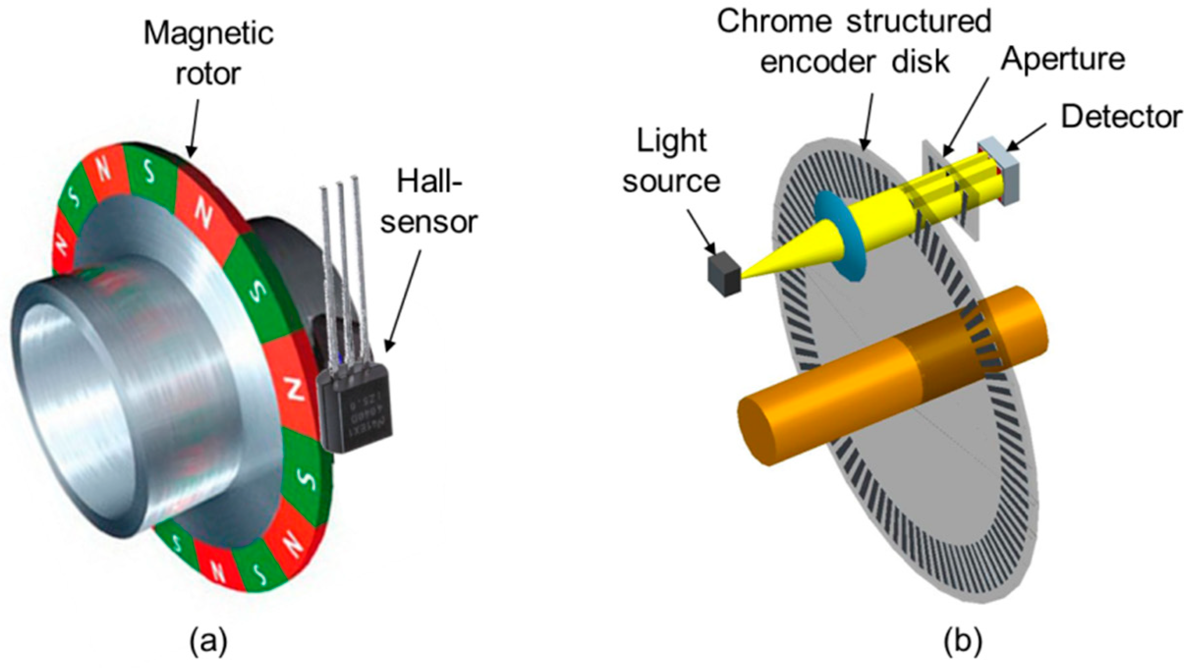
Figure 1. (a) Operating principle of a magnetic encoder with a magnetic rotor and hall sensor; (b) operating principle of an optical encoder with a light source, encoder disc, aperture, and detector.
Applsci 09 00452 g001
Figure 2. (a) Encoder disc of an absolute optical encoder with Gray code patterns of opaque and transparent parts; (b) cross-section of the optical path.
Applsci 09 00452 g002
Figure 3. Diffraction of light by a reflective phase grating.
Applsci 09 00452 g003
Figure 4. Functional principle of the optical encoder.
Applsci 09 00452 g004
Figure 5. Two different layouts for the photodetector of the optical encoder. (a) Segmented arrangement of the photodiodes; (b) Gray code arrangement of the photodiodes.
Applsci 09 00452 g005
Figure 6. Design of the optical path for the encoder. (a) Optical path for the segmented photo detector; (b) optical path for the photo detector with Gray code arrangement of the photodiodes.
Applsci 09 00452 g006
Figure 7. Demonstrator for proof of principle. (a) Glass lid with laser diode; (b) High Dynamic Range complementary metal-oxide semiconductor (CMOS) (HDRC®) image sensor with the glass lid and lens on top of it; (c) blazed grating on a rotatable shaft; (d) fully assembled demonstrator.
Applsci 09 00452 g007
Figure 8. Spot shape measured with log-scale HDRC® image sensor.
Applsci 09 00452 g008
Figure 9. Spot shape measured with log-scale HDRC® image sensor.
Applsci 09 00452 g009
Figure 10. Read-out circuit of the Gray code structure (photodiode ring bit 1).
Applsci 09 00452 g010
Figure 11. Read-out circuit of the segmented photodiode an optical application-specific integrated circuit (opto-ASIC).
Applsci 09 00452 g011
Figure 12. Cross-section of the demonstrator for the miniaturized optical encoder.
Applsci 09 00452 g012
Figure 13. Assembly concept of the demonstrator. (a) Assembly of the opto-ASIC onto the printed circuit board (PCB) and the laser diode onto the opto-ASIC; (b) assembly of the lens onto the opto-ASIC; (c) assembly of the housing; (d) assembly of the encoder disc, the bearing, and the shaft.
Applsci 09 00452 g013
Figure 14. Microscope images of the opto-ASICs. (a) Opto-ASIC with segmented photodiodes; (b) opto-ASIC with Gray code photodiode structure.
Applsci 09 00452 g014
Figure 15. Opto-ASIC mounted onto PCB with assembled laser diode on the additional metal top layer, in comparison to Figure 12.
Applsci 09 00452 g015
Figure 16. Lens mounted on top of the opto-ASIC.
Applsci 09 00452 g016
Figure 17. Design of the injection mold for encoder discs.
Applsci 09 00452 g017
Figure 18. Injection-molded encoder disc with blazed grating.
Applsci 09 00452 g018
Figure 19. Completely assembled demonstrator for the miniaturized optical encoder.
Applsci 09 00452 g019
Figure 20. Example of the Gray code encoder signals (bit 6) for one revolution (360°).
Applsci 09 00452 g020
Figure 21. Signals of the Gray code encoder for all bits over a small angular range.
Applsci 09 00452 g021
Figure 22. Encoder with the segmented photodiodes. (a) Laser spot on the photo detector; (b) user interface for evaluation of the position of the laser spot.
Applsci 09 00452 g022
Table 1. Examples of high-end state-of-the-art encoders.
Feature/SeriesCUI MAS10CUI MES6
MethodAbsoluteIncremental
Resolution256 positions500 positions
Speed6000 rpm6000 rpm
InterfaceDigitalDigital
Temperature0…+60 °C0…+60 °C
SizeØ 13 mm × 16 mmØ 8 mm × 11 mm
Table 2. The most important features of the encoder; SPI—Serial Peripheral Interface.
Feature
MethodIncremental and absolute
Resolution1024 positions
Speed12,000 rpm
InterfaceDigital and SPI
Temperature−40 … +85 °C
Size10 × 10 × 10 mm3