Article

Exhaust Gas Characteristics According to the Injection Conditions in Diesel and DME Engines

1
Industry-University Cooperation (LINC), Chosun University, 309 Pilmun-daero, Dong-gu, Gwangju 61452, Korea
2
Department of Mechanical and Shipbuilding Convergence Engineering, Pukyung National University, Busan 48547, Korea
*
Author to whom correspondence should be addressed.
Appl. Sci. 2019, 9(4), 647; https://doi.org/10.3390/app9040647
Submission received: 18 December 2018 / Revised: 12 February 2019 / Accepted: 12 February 2019 / Published: 14 February 2019

Abstract

:
In this paper, the effect of high-pressure injection pressure on particulate matter (PM) and nitrogen oxide (NOx) emissions is discussed. Many studies have been conducted by active researchers on high-pressure engines; however, the problem of reducing PM and NOx emissions is still not solved. Therefore, in the existing diesel (compression ignition) engines, the common rail high-pressure injection system has limitations in reducing PM and NOx emissions. Accordingly, to solve the exhaust gas emission problem of a compression ignition engine, a compression ignition engine using an alternative fuel is discussed. This study was conducted to optimize the dimethyl ether (DME) engine system, which can satisfy the emission gas exhaust requirements that cannot be satisfied by the current common rail diesel compression ignition engine in terms of efficiency and exhaust gas using DME common rail compression ignition engine. Based on the results of this study on diesel and DME engines under common rail conditions, the changes in engine performance and emission characteristics of exhaust gases with respect to the injection pressure and injection rate were examined. The emission characteristics of NOx, hydrocarbons, and carbon monoxide (CO) emissions were affected by the injection pressure of pilot injection. Under these conditions, the exhaust gas characteristics were optimized when the pilot injection period and needle lift were varied.

1. Introduction

In order to prevent air pollution caused by exhaust gas from automobiles, exhaust emission regulations such as Tier-III and EURO-VI have been announced in various countries such as USA, Europe and Japan. Many researchers are working to reduce harmful emissions by gradually increasing the allowable regulation of hazardous emissions from automobiles [1]. Diesel engines have been widely used as power sources for automobiles and ships because of their high thermal efficiency and fuel efficiency. It has the advantage of low carbon monoxide (CO) and unburned hydrocarbons (HC) because it burns under lean conditions where the fuel consumption rate is lower than that of the gasoline engine and the combustion state is excess oxygen. However, since it has the disadvantage of high PM (particulate matter) and NOx (nitrogen oxides) emissions, it cannot satisfy the increasingly stringent emission regulations [2,3].
Using diesel particulate filters (DPF) together with diesel oxidation catalysts (DOC) is a technology that can reduce the emissions of diesel cars to the level of the latest gasoline vehicles. There have been many studies on nitrogen oxides in various countries depending on the social environment and economic conditions. However, in Europe, selective catalytic reduction (SCR) and US prefer the NOx storage catalyst (LNT, Lean NOx trap) [4]. The exhaust emission reduction technique using the above-described exhaust after-treatment apparatus reduces emissions discharged through the engine combustion process to a separate device in the exhaust system. The soot purification apparatus and the NOx storage catalyst are excellent in filtering soot and NOx components, respectively Performance. However, in order to apply the actual engine, it is necessary to remove the accumulated soot or SOx through a process called regeneration while monitoring the state before and after the filter [5,6,7]. A number of studies have been conducted to reduce exhaust gases such as nitrogen oxides and soot using various fuel properties and additives [6,7], multiple injection [8,9], EGR [10,11,12] and PCCI/SCCI/CAI [13,14,15,16].
DME (dimethyl ether, CH3-O-CH3) among alternative fuels for diesel engines has low auto ignition temperature. It also has good evaporative performance when sprayed into the combustion chamber and has a higher cetane number (>55) than the diesel fuel. In particular, DME is an oxygen-containing fuel containing about 34.8 wt% of oxygen, and because there is no direct coupling between carbon and carbon in the fuel characteristics, almost no PM is being emitted in the diesel engine [17,18,19,20,21,22,23]. Due to these advantages, it is possible to apply a large amount of exhaust gas recirculation (EGR) without much difficulty to the engine, and it can greatly reduce NOx, and it has many excellent characteristics as an alternative fuels for diesel engines [24,25,26,27,28].
This is because it is easy to change and improve parameters affecting injection characteristics such as injection timing, injection duration, and injection pressure and injection quantity independently of engine rotation through electronic control. It is a great advantage to have superior advantages compared to the existing diesel engines such as output, fuel consumption, noise and vibration, and reduction of NOx in exhaust gas through electronic control according to each 4 conditions [29,30,31]. Experiments and numerical studies on spray combustion and exhaust characteristics for compression ignition engines using DME fuel have been conducted by many researchers. Numerical studies on compression ignition engines show that the application of diesel alternative fuels is largely dependent on the physical and chemical properties of the fuel and the application of a chemical reaction mechanism for combustion simulation Teng et al. [32] used the results of the study on the thermodynamic properties of DME fuel and the fuel property data of the AVL FIRE program [28] as input to the fuel material subproject of KIVA-3V code. Numerical analysis of the compression ignition engine using DME fuel was performed by applying the detailed reaction mechanism of DME fuel proposed by Fisher and Curran et al. [33,34]. Comparisons with experimental results confirm that the results of the numerical analysis simulate the spray combustion and exhaust characteristics well.
In this study, the effects of engine performance, injection pressure and pilot injection period using injection pressure and injection rate on diesel and DME engines, pilot injection rate as a function of injection timing, and needle lift and injection timing on exhaust gas characteristics were investigated to optimize the DME combustion engines.

2. Experimental Apparatus and Methodology

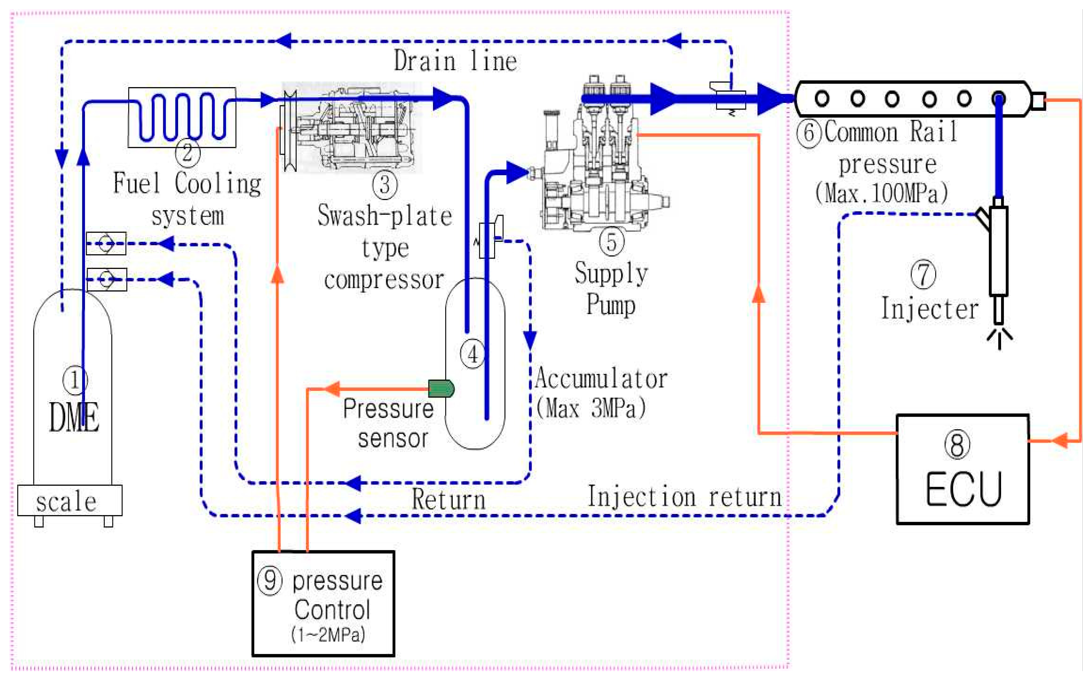
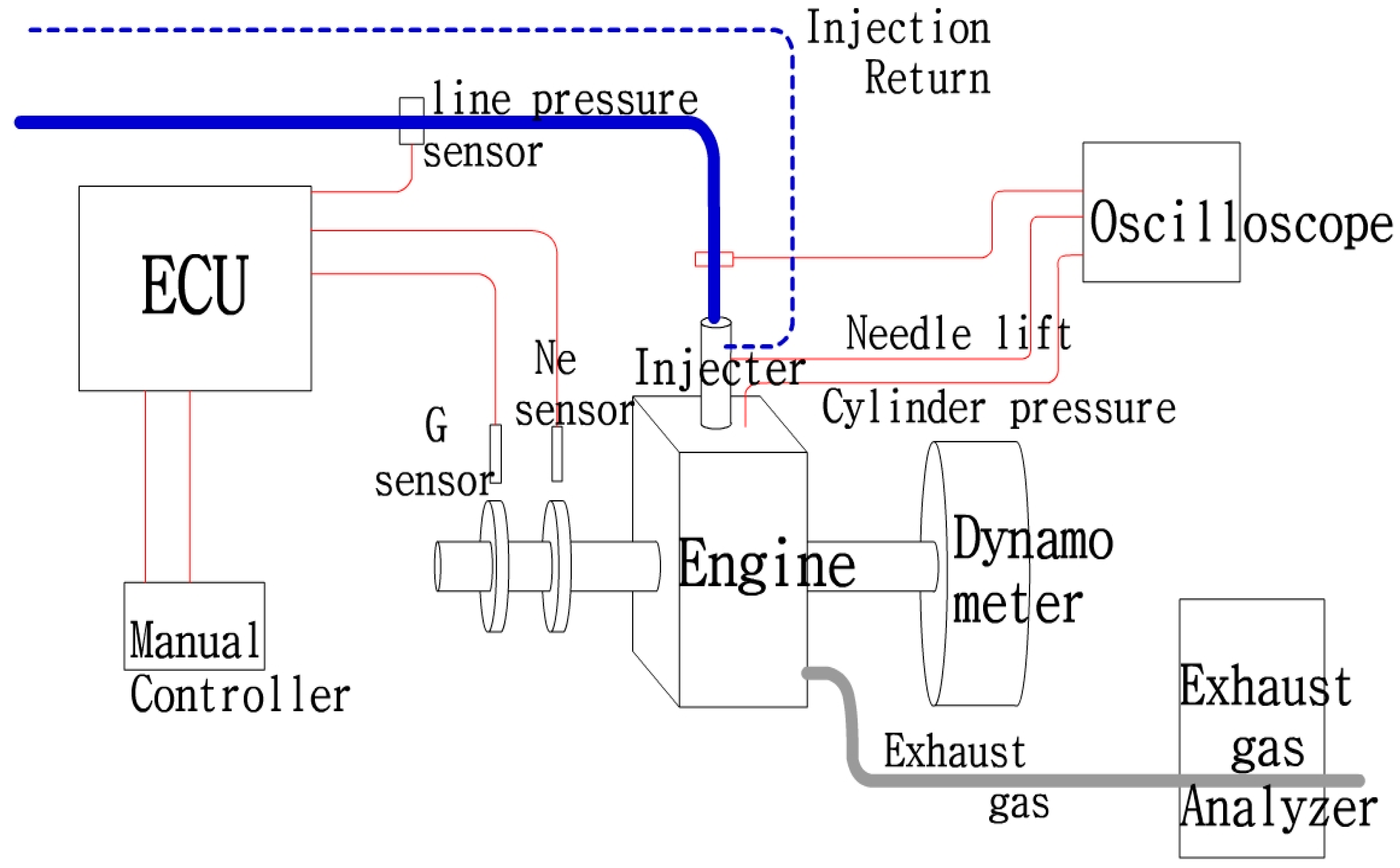
2.1. Experimental Setup

To prevent the occurrence of vapor lock because of the DME characteristics, an experimental setup was designed and fabricated, as shown in Figure 1, using a vapor lock prevention device (liquid holding device), a booster, and a special plunger pump (gas booster and liquid pump from HASKEL) for the adhesion possibility of the sliding parts.
The experimental engine shown in Table 1 is an engine from Daedong, which is a water-cooled single-cylinder four-cycle direct-injection diesel engine. Its specifications are total displacement of 673 cc, maximum output of 9.11 kW with 2200 rpm, and maximum torque of 4.22 kg m with 1800 rpm.
The injection period pulse (using AM503B current probe amplifiers from Tektronix, Beaverton, OR, USA) was performed for the common rail injector injection characteristics and compared with the actual injection amount. The line pressure according to the two-way pulse was measured (using 4067A2000 amplifiers from KISTLER, Winterthur, Switzerland) to confirm the pilot of the injection lift operating period and the pressure fluctuation of the main injection. The injection needle lift was measured (using signal condition amplifiers from WOLF, Boston, MA, USA) to compare it with the line pressure under the loading condition of the engine. In addition, the injection rate, which is the core of the common rail high-pressure injection characteristics, was measured (Japan KYOWA Electric Corporation (Tokyo, Japan), signal condition: CDV700A, bridge box: DB120, strain gauge: KFG-03). Figure 2 shows the fuel injection control system and test engine configuration. The engine control system in this study applied the ECD-U2 common rail system manufactured by NIPPON DENSO (Tokyo, Japan). To input the engine revolutions and crank positions into the engine control unit (ECU), Ne pulse (crank position pulse) for injection characteristics experiments and Ge pulse (cylinder detect pulse) embedded in the supply pump were used. For the measurement of exhaust gases, non-dispersive infrared spectrometry (using MEXA 324JK from HORIBA) was performed for CO and THC, the chemiluminescence method (using the 10 AR model of the thermo environmental instrument) for NOx, and the reflection photometer method (AFT-2000 from World Environment) for smoke. The data obtained from these instruments were used as a representative value using the average value for the three measurement results.

2.2. Experimental Methodology

Fuel injection conditions were changed by controlling the injection timing, injection duration, injection pressure, pilot injection rate, and injector needle lift using the ECU program.
The injection timing (10°, 14°, 18°, and 22° before top dead center (BTDC)) was adjusted using the common rail injection device manual controller based on the injection timing (22° BTDC) of the mechanical injection pump in accordance with the specifications of the single-cylinder horizontal diesel engine that was used as the test engine. In this instance, the injection lift (0.14, 0.21, 0.24, and 0.36 mm) was changed based on the injection nozzle (ψ = 0.22 mm × 5 ea), and the injection characteristics, engine performance, and exhaust gas characteristics were investigated according to the pilot and main injections. The engine revolutions were 1800 rpm, load ratio was 75%, and common rail injection pressure was 50 MPa. The braking thermal efficiency was focused on maintaining the current common rail engine and reducing NOx among the exhaust gases [10,11,12].

3. Results and Investigations

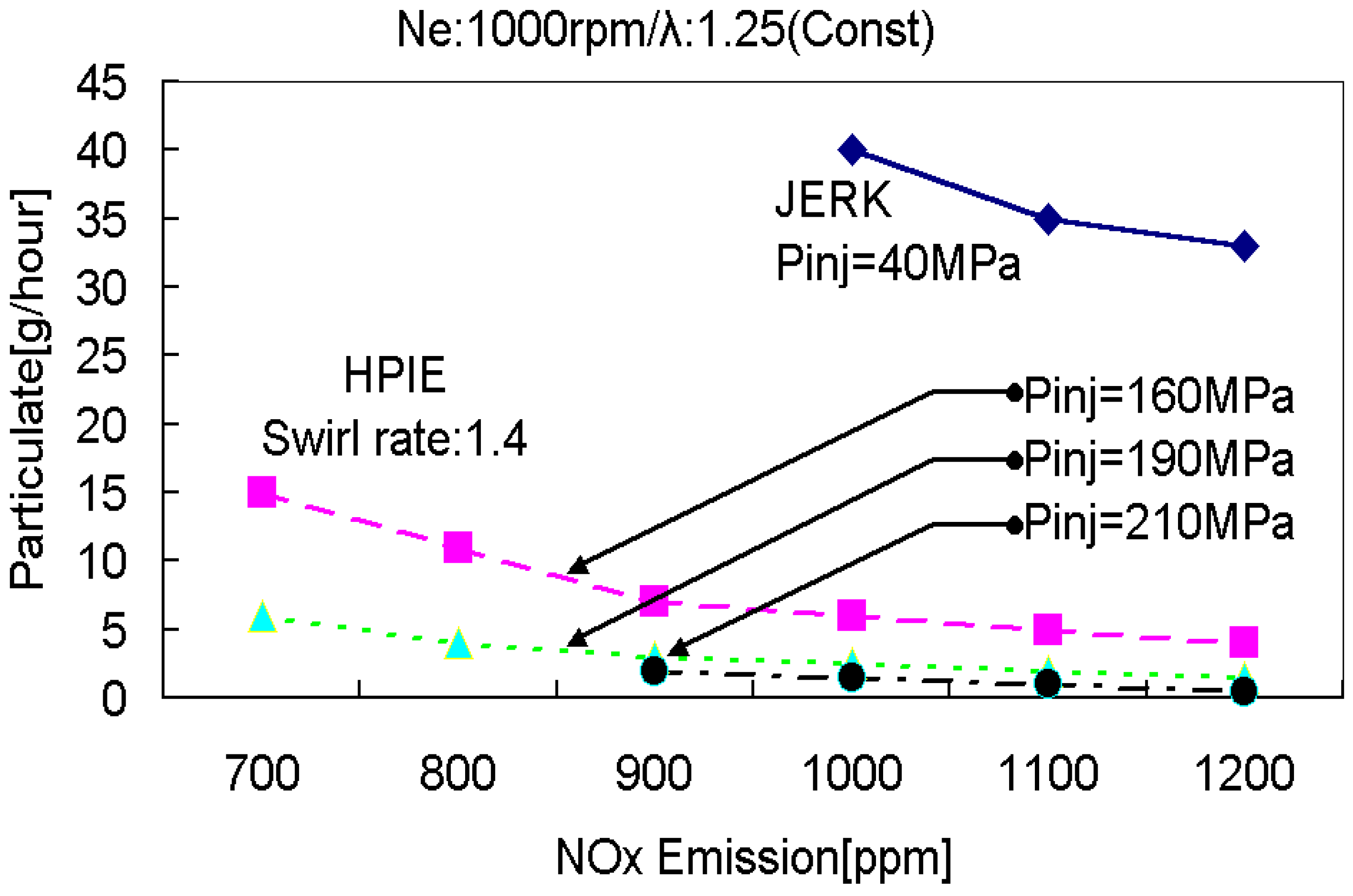
3.1. Effects of Atomization on Exhaust Gas

Figure 3 shows the effect of high-pressure injection pressure on PM and NOx emissions. Many studies have been conducted by active researchers on the high-pressure engine; however, the problem of reducing PM and NOx emissions is still not solved. In the existing diesel (compression ignition) engines, the common rail high-pressure injection system has limitations in reducing PM and NOx emissions. Therefore, to solve the exhaust gas emission problem of the compression ignition engine, a compression ignition engine using an alternative fuel was studied [21,22,23,24]. In this study, the exhaust gas problem, which cannot be solved by the existing common rail diesel compression ignition engine, was solved with the optimization of a DME engine system that can satisfy both efficiency and exhaust gas emission.
Table 2 presents the causes of PM and NOx generation and the mitigation measures. To solve the problem of exhaust gas emission from conventional fossil fuels of compression ignition engines, DME, which is a natural gas reforming fuel, was used as an alternative fuel. The thermal efficiency of the compression ignition engines using the DME fuel was studied to determine the optimal injection conditions to maintain the current level of common rail diesel engines and simultaneously reduce the PM and NOx emissions.

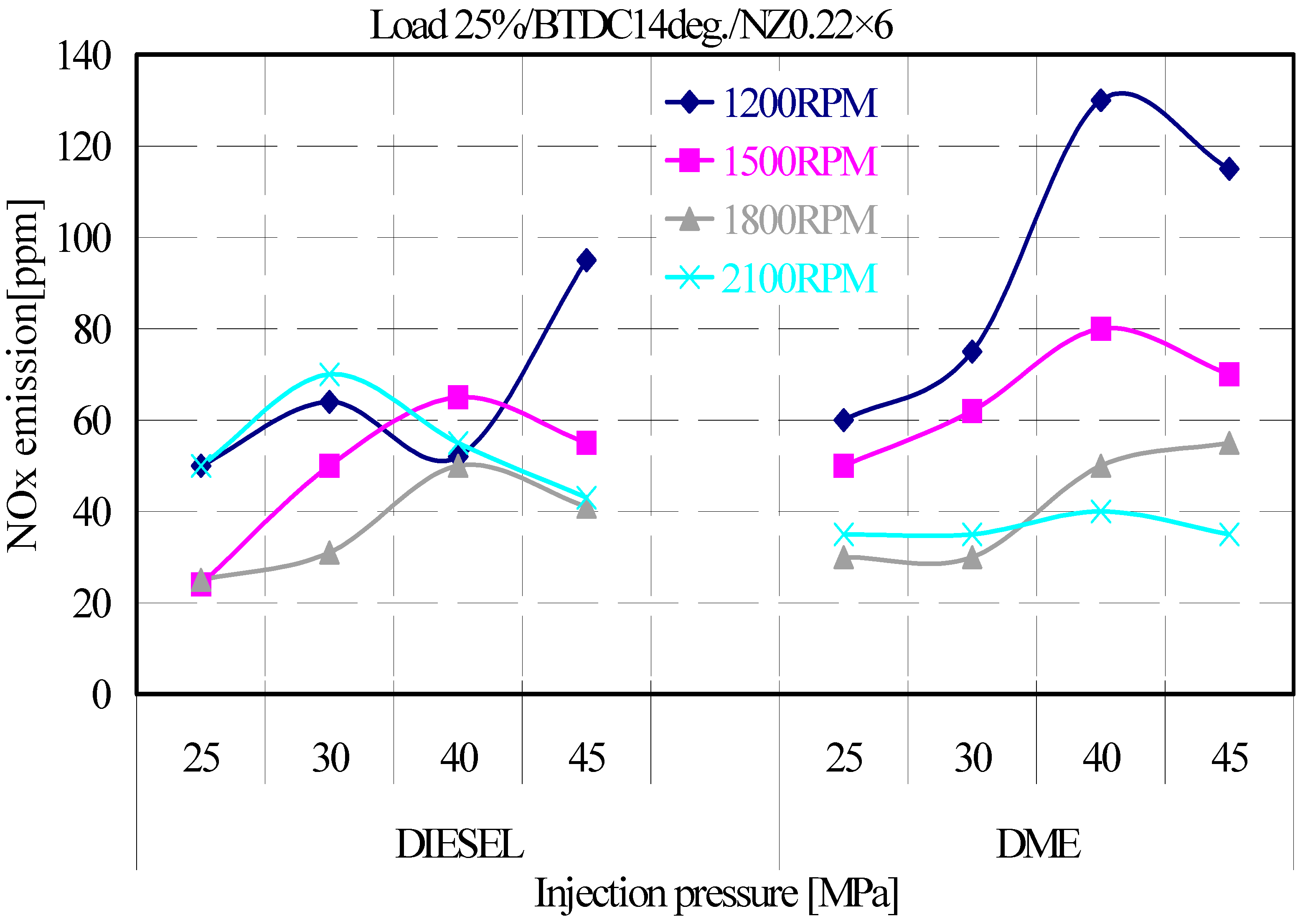
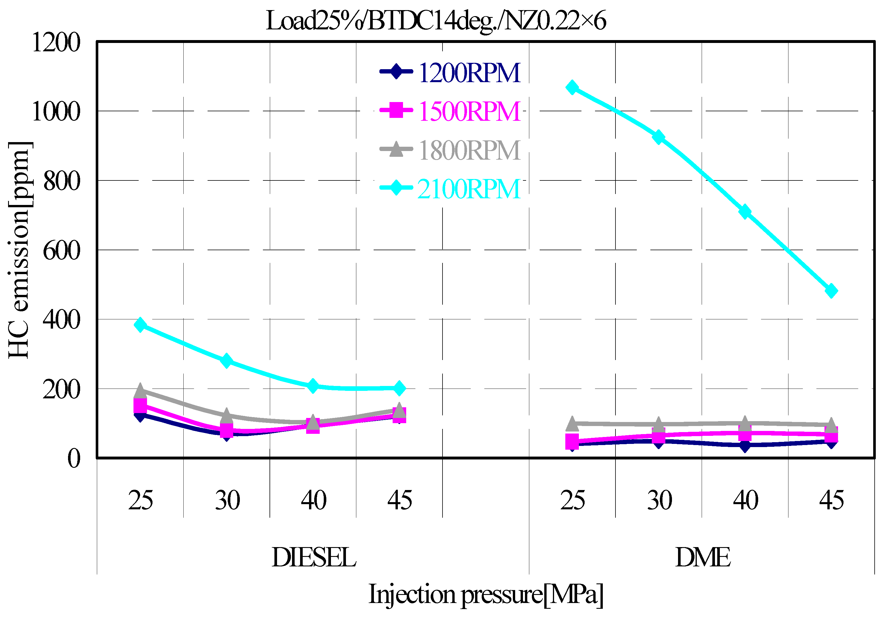
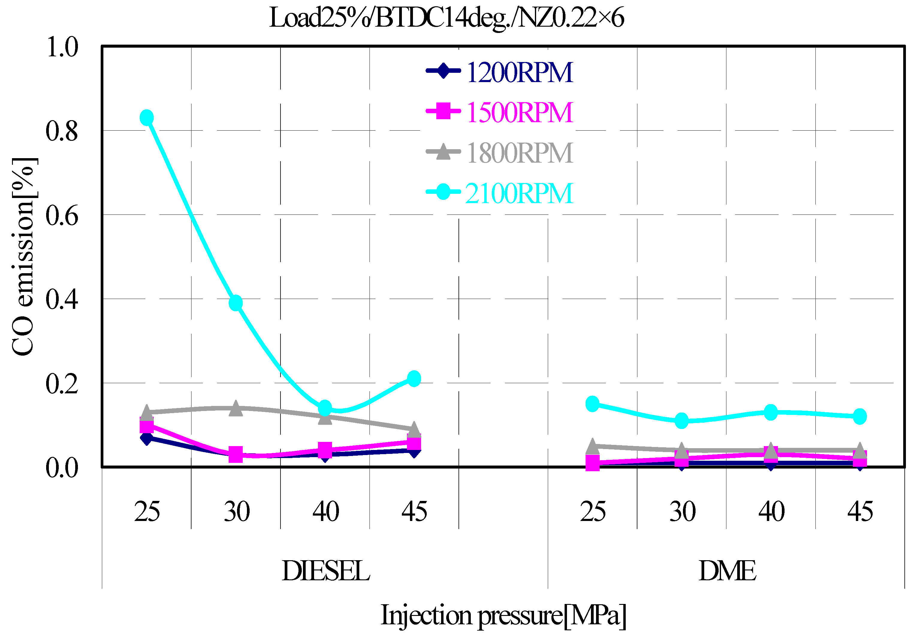
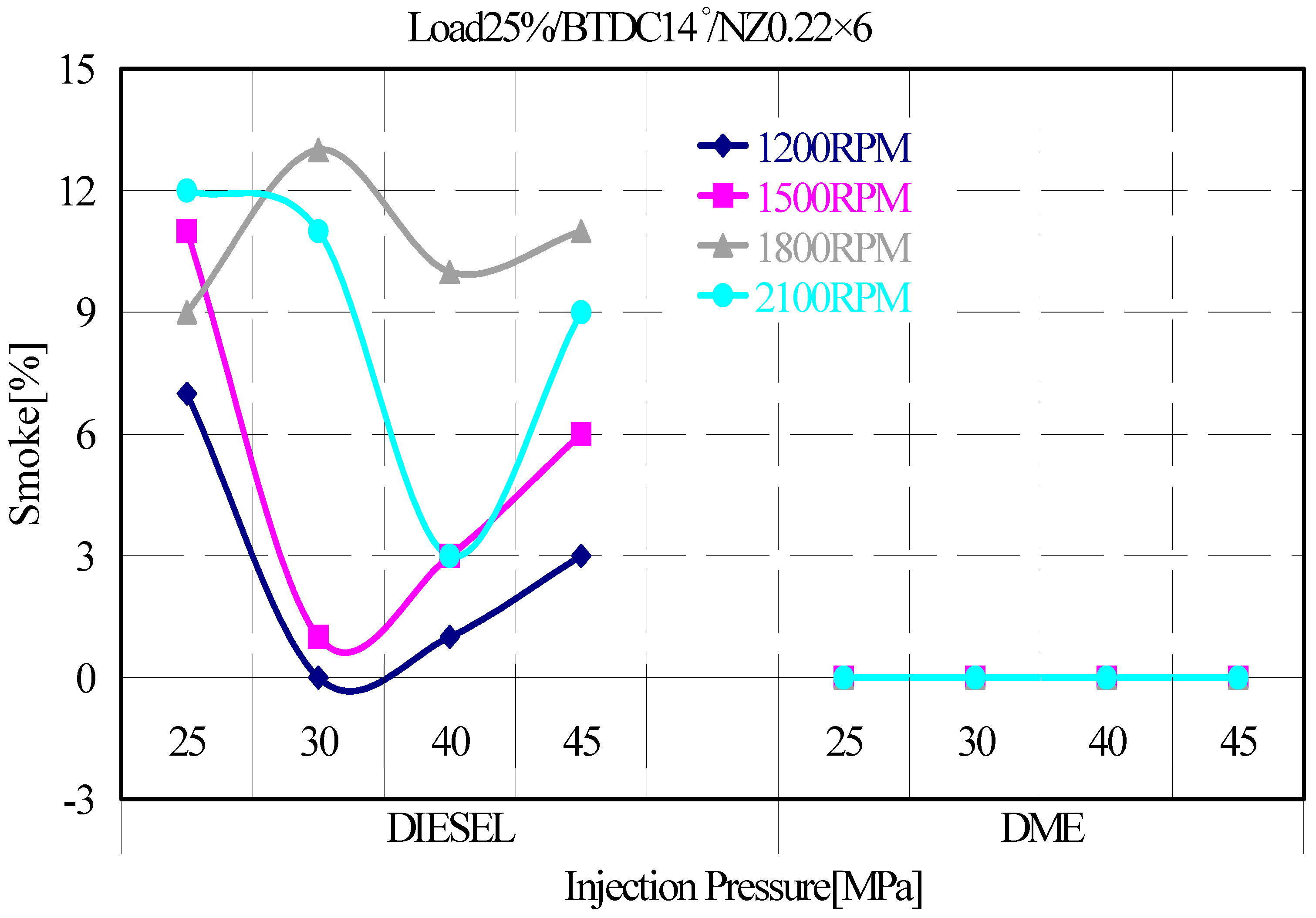
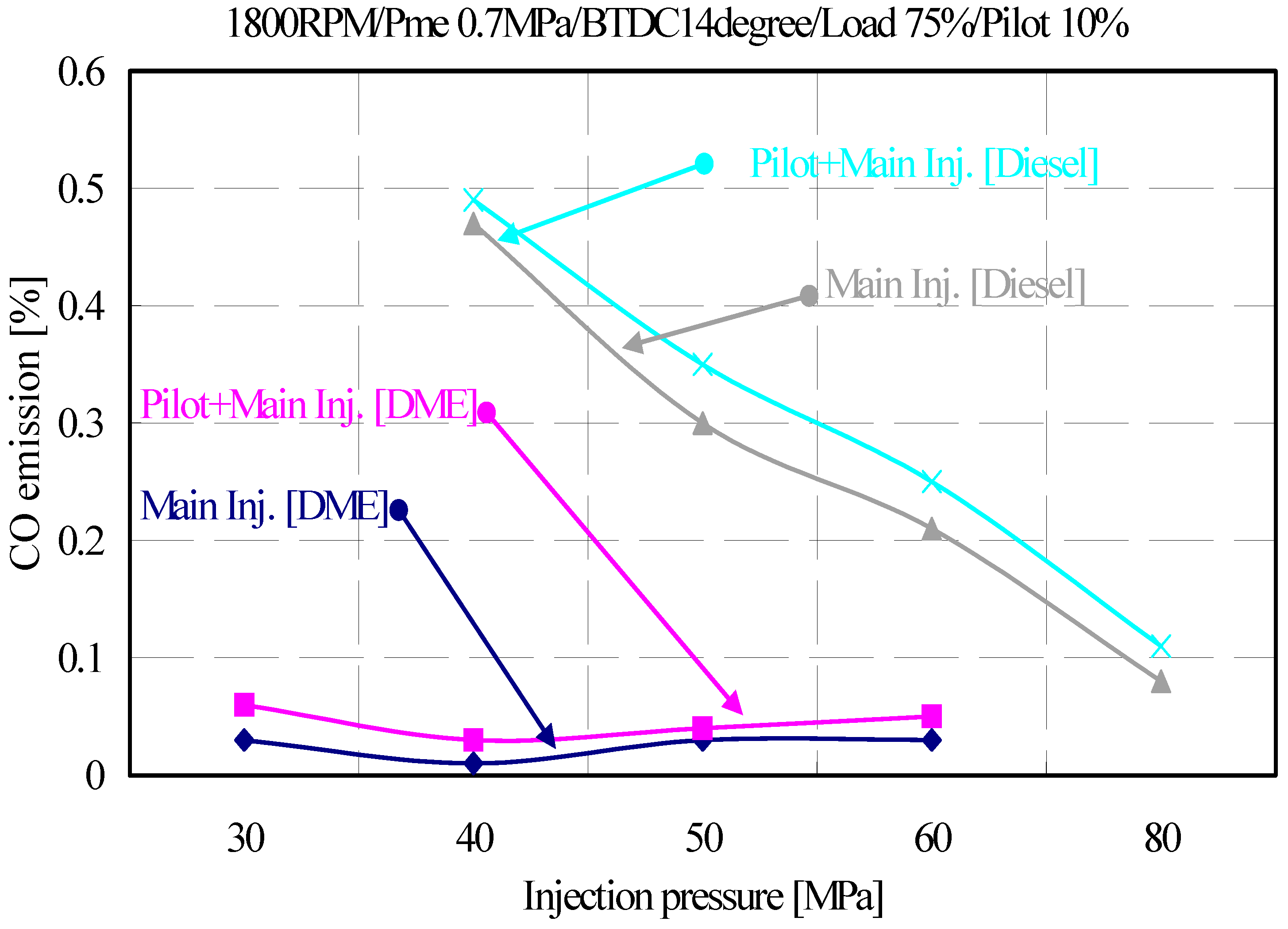
3.2. Effects of Injection Pressure on Exhaust Gas Emission Characteristics of Diesel and DME Engines

1. NOx emission characteristics of diesel and DME engines
Figure 4 shows a comparison of the exhaust gas emission characteristics of DME and diesel engines depending on the injection speed and pressure of the engines at an injection timing of 14° BTDC and 25% load factor.
NOx emissions in DME engines are not significantly different from those in diesel engines; however, the emission characteristics of the fuel injection pressure are different.
In particular, NOx emissions are lowest at 2100 rpm in DME engines, unlike those in diesel engines. This suggests that the DME engine used in this study has an unstable combustion state because of the non-optimized fuel injection conditions, such as injection timing and amount according to the injection pressure of the fuel. Thus, the combustion state of the DME fuel, which is an oxygen fuel, is generally improved, thereby increasing the combustion temperature and NOx emission concentration [58,59]. This is consistent with the emission characteristics of other internal combustion engines. Therefore, it suggests that it is necessary to investigate the possibility of reducing NOx emissions in DME engines using the fuel injection pressure characteristics.
2. HC emission characteristics of diesel and DME engines
Figure 5 shows the emission characteristics of the unburned HC in DME and diesel engines depending on the engine operating speed and injection pressure with light load and injection timing of 14° BTDC.
At the engine operating speed of 1200–1800 rpm, the HC emissions were slightly lower than the diesel engine emissions. However, at the operating speed of 2100 rpm, the HC emissions of the DME engines were about 2.5 times higher than those of the diesel engines. This indicates that the combustion characteristics of oxygenated fuel appeared in the low-speed range but in the case of 2100 rpm the emission of HC was increased compared with 1200–1800 rpm by incomplete combustion. The excessive injection amount because of the high-pressure injection and the inconsistency of the injection timing was shown in the high-speed operation condition. In DME engines, the effect of fuel injection pressure on the HC emission characteristics were not significant at low speeds; however, at high speeds, the higher was the fuel injection pressure, the lower was the HC emission. To optimize the DME engines, it was necessary to optimize the fuel injection pressure and injection amount for the engine operating conditions.
3. CO emission characteristics of diesel and DME engines
Figure 6 shows the CO emission characteristics of DME and diesel engines depending on the engine operating speed and injection pressure with light load and injection timing of 14° BTDC. The emission characteristics of CO were similar to those of HC. The CO emission concentration of the DME engine was slightly lower than that of the diesel engine at all operating conditions and not significantly affected by the fuel injection pressure. This was because of the combustion characteristics of the oxygenated fuel of the DME, as described in HC.
4. Smoke emission characteristics of diesel and DME engines depending on the injection pressure and number of revolutions
Figure 7 shows a comparison of the soot concentration with the injection pressure for operating speed of DME and diesel engines at the engine operating speed of 1800 rpm, light load condition, and injection timing of 14° BTDC. The exhaust gas emission characteristics of DME engines were not discharged as compared to those of the diesel engine [33,34,60]. As a result of injecting high-pressure liquid fuel DME, which is a compressible oxygen fuel, the mixing ratio with air in the injection characteristic improved as compared to that with diesel, thereby enhancing the diffusive combustion state due to inject the high-pressure fuel.

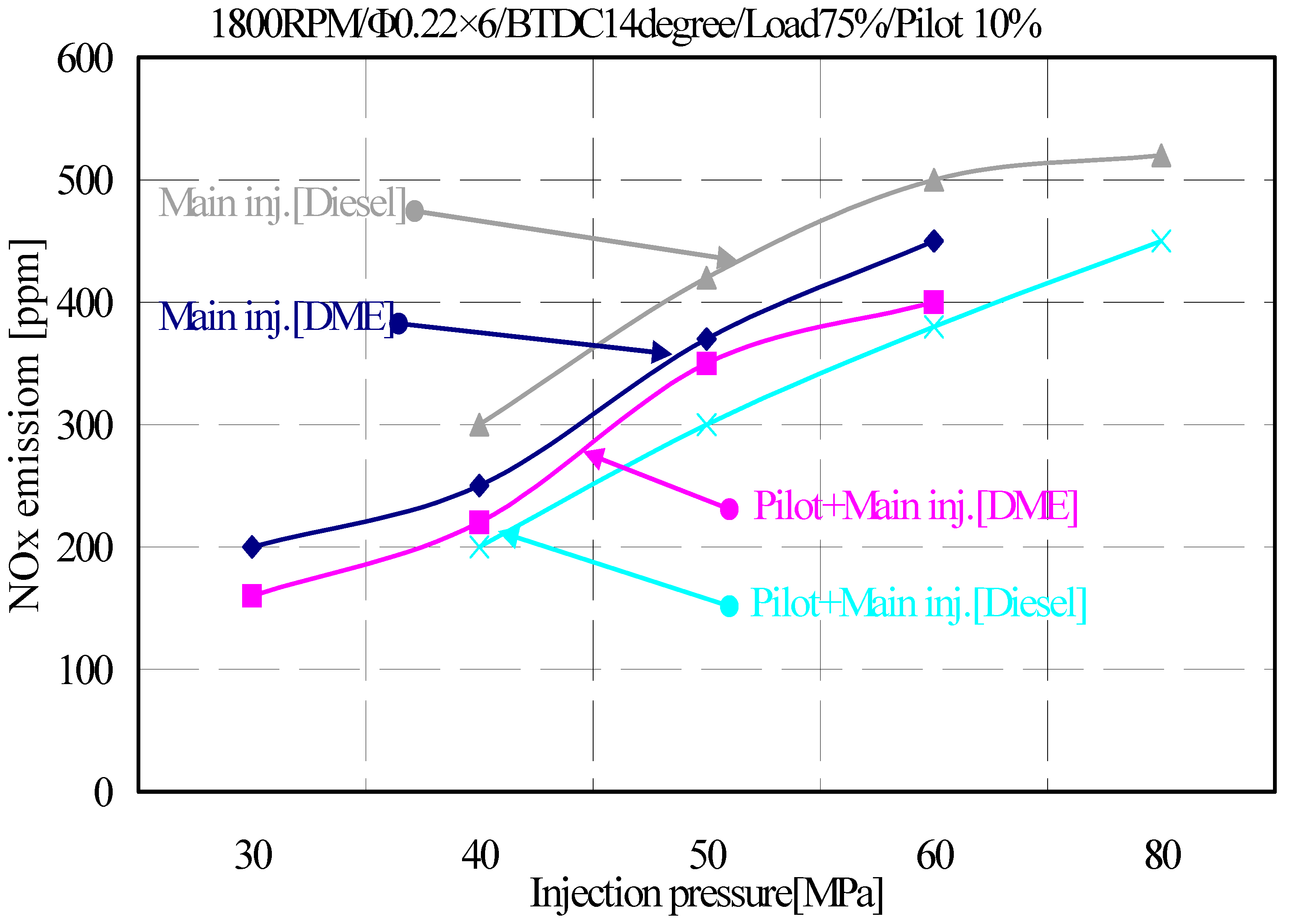
3.3. Effects of Injection Pressure and Pilot Injection Period on Exhaust Gas Emission Characteristics of DME Engines

1. NOx emission characteristics of diesel and DME engines depending on the injection pressure and pilot injection period
Figure 8 shows that the NOx emissions of DME as a diesel alternative fuel was more than those of diesel near the top dead center (TDC) at the same diesel injection timing of the experimental engine. As the injection pressure increased, the amount of NOx increased, and pilot injection showed that the diesel could be reduced to 20% (100 ppm) and DME to 10% (50 ppm). In this experiment, based on improving the diesel injection timing as much as possible and the pilot injection about 15% of the total injection amount, it was confirmed that NOx could be reduced to about 10–20% of the total emission rate by high-pressure fuel injection and pilot injection. For pilot injection at 6° before the 14° BTDC, where combustion occurred, the thermal efficiency decreased with increasing fuel consumption rate; however, it was expected that the NOx generated in a high-temperature region would be reduced because the temperature of the combustion chamber decreases.
2. HC emission concentration in diesel and DME engines depending on the injection pressure and pilot injection period
Figure 9 shows the HC emission with pressure during high-pressure pilot and main injections. HC was reduced by more than 50% in this study as compared to those in other studies (injection pressure 20–35 MPa) [24,26] for high-pressure pilot injection. HC was generated in the combustion chamber wall or in a state where the air–fuel ratio was rich, and it was generated in a state where the fuel was vaporized and not oxidized. Moreover, DME, as an oxygenated fuel, generated almost no HC, and generated higher fuel density per unit volume. Furthermore, unlike the emission characteristics of NOx, the emission rate of HC was reduced by the increase of pressure. It could be expected that, as the injection pressure increases, the injection amount in the diesel and DME engines for the injection period is optimized in the laboratory, and incomplete combustion is less likely to occur.
3. CO emission concentration in diesel and DME engines depending on the injection pressure and pilot injection period
Figure 10 shows the CO emission rate as a function of pressure when performing high-pressure pilot and main injections. CO is generally generated in an incomplete combustion environment because of lack of oxygen in an excess fuel state, which was not a problem because DME is an oxygenated fuel, and compression ignition engines are not a big problem because they operate in a lean air–fuel ratio region. In this study, the CO emission rate was lower than that of the diesel engine.

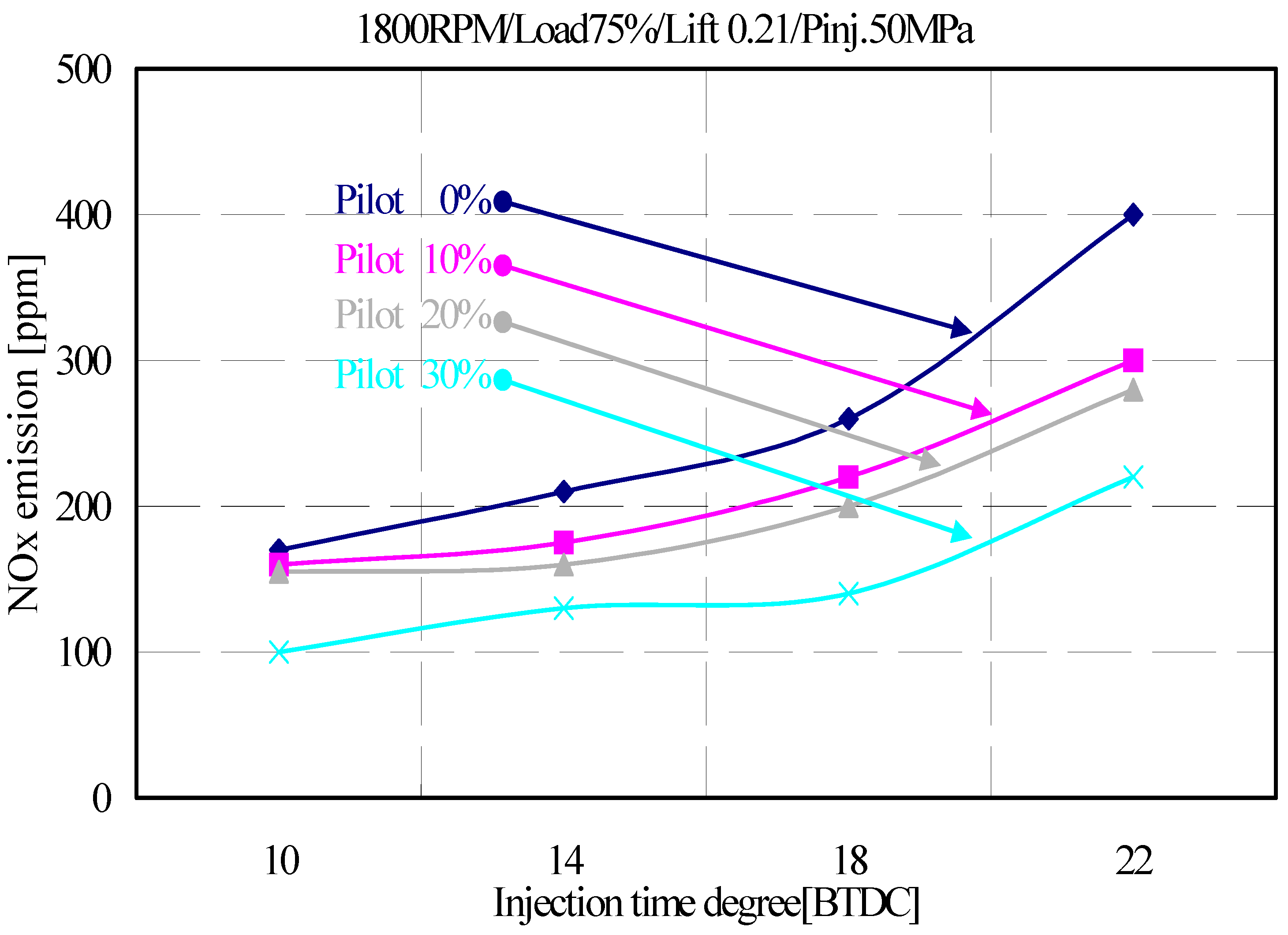
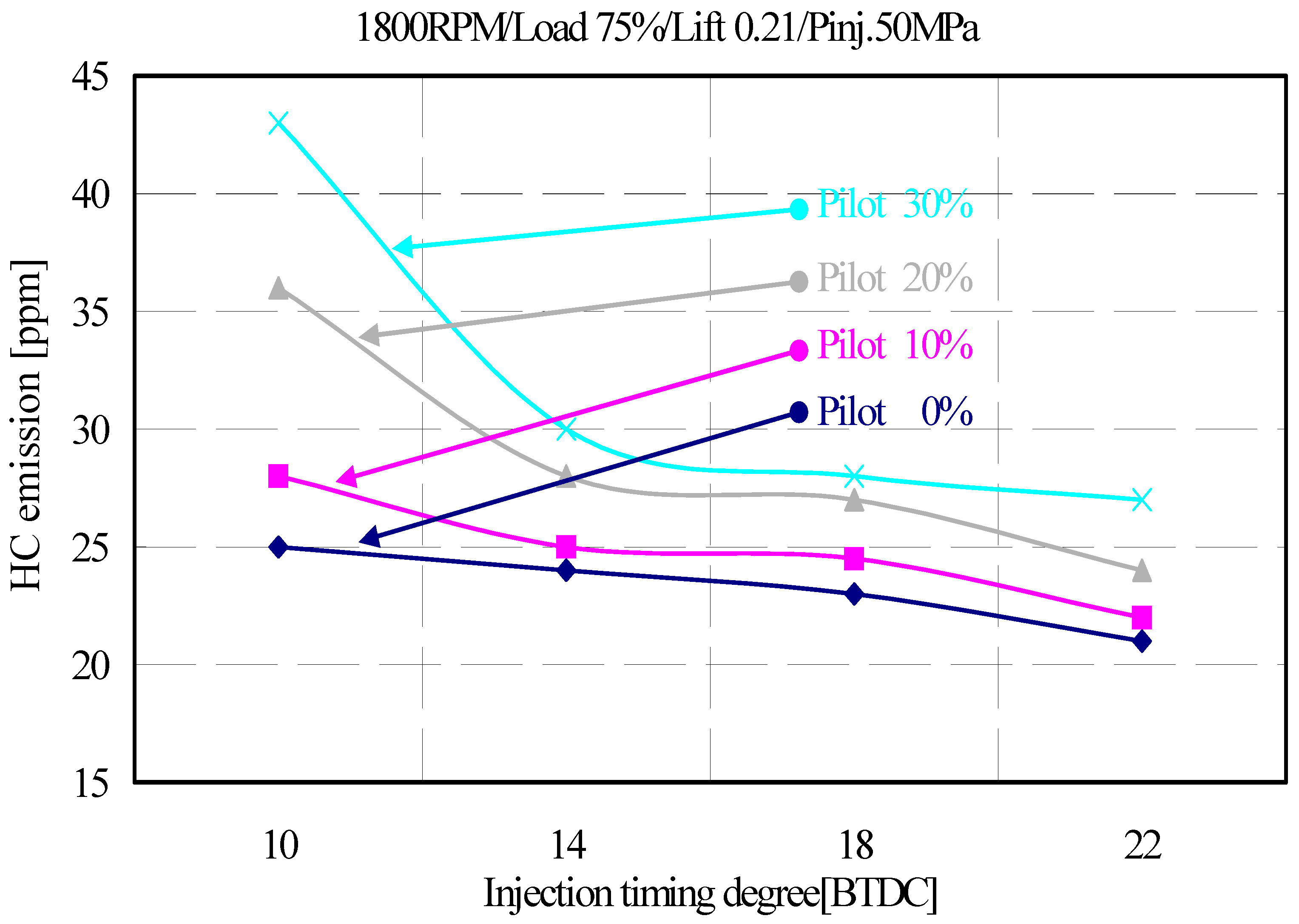
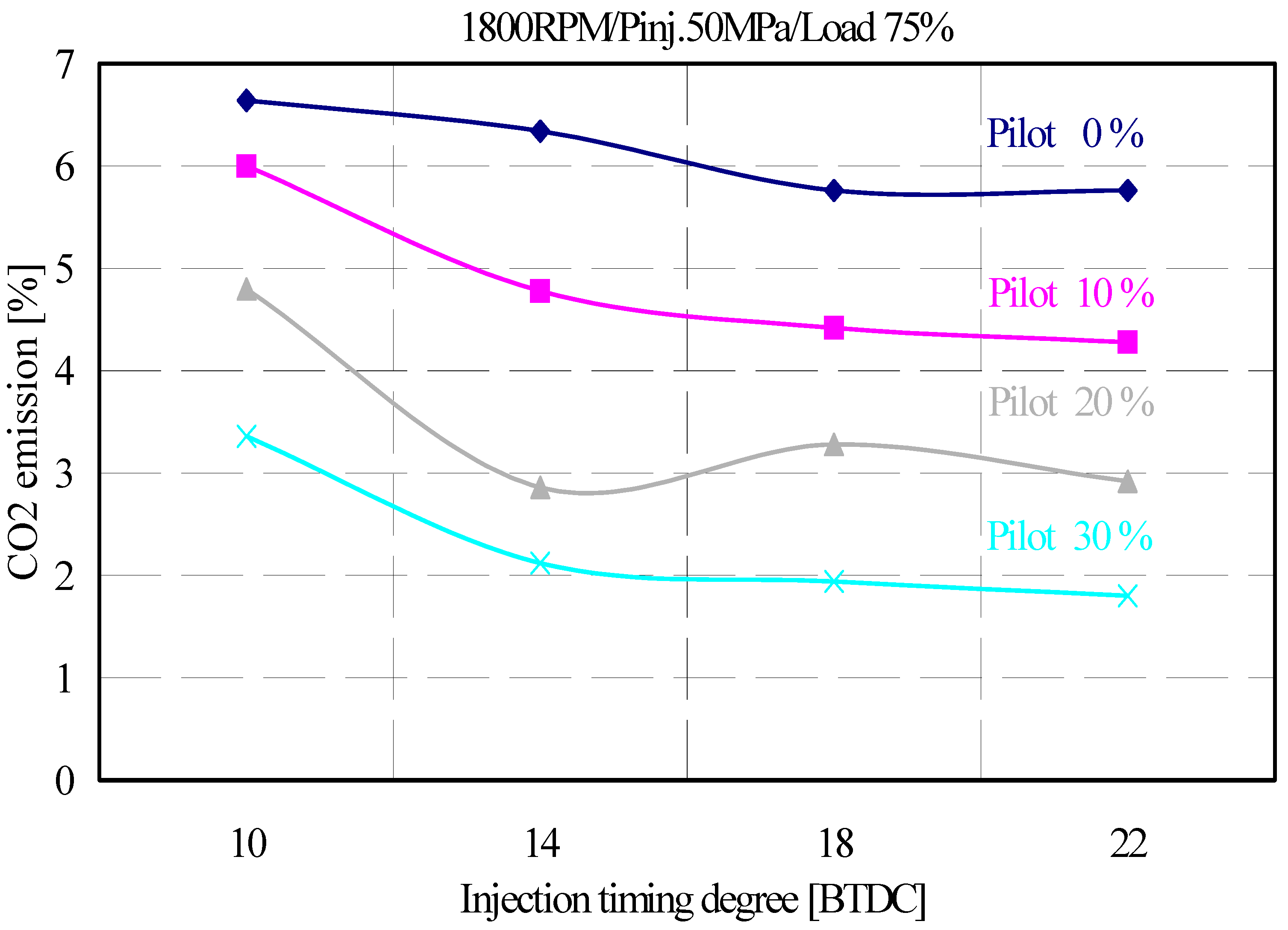
3.4. Effects of Pilot Injection Rate on Exhaust Gas According to Injection Time in DME Engines

In this study, the emission characteristics of HC, NOx, CO, and carbon dioxide (CO2) were analyzed for the engine performance tests. DME showed unleaded combustion and no special combustion method was required for exhaust gas reduction. However, NOx and HC vary depending on the operating conditions and fuel characteristics; thus, the reduction rate was investigated for each pilot injection rate, injection timing, needle lift, and injection timing in this experiment.
1. NOx emission characteristics of DME engines depending on the injection pressure and pilot injection period
Figure 11 shows the effect of pilot injection period on NOx emissions with injection timing; other studies [35,39,46] have shown that the NOx emission rate of DME as a diesel substitute fuel decreases as it approaches the TDC. Therefore, in this experiment, the pilot injection rate was examined from 0% to 30% of the total injection amount with the injection pressure of 50 MPa and the injection timing at the lowest was 10° BTDC and at the highest was 22° BTDC. As a result, NOx decreased as the pilot injection rate increased. This was because the pilot injection before the main injections slowed the diffusion combustion because of the injection period delay. Furthermore, it reduced the combustion chamber temperature and average effective pressure because the injection delay decreased, thereby reducing the emission of NOx generated at high temperatures. NOx was mostly composed of nitrogen monoxide (NO) and nitrogen dioxide (NO2), which were produced by the combination of nitrogen molecules in the air and oxygen at high temperatures. NOx in the compression ignition engine were divided into thermal NO and fuel NO, oxidized by the nitrogen contained in the fuel, most of which was thermal NO. The generation mechanism was based on the Zeldovich mechanism and had a mechanism (N2 + O → NO + N) in which NO molecules dissociated during combustion in an excess air atmosphere to produce NO. The generation of NO by this dissociation was a strong endothermic reaction, which exponentially increased at high temperatures and was discharged during the expansion stroke. That is, the concentration of NO was greatly dominated by the combustion temperature, and the reaction time and oxygen concentration were also important factors.
2. HC emission characteristics of DME engines depending on the injection timing and pilot injection rate
Figure 12 shows the effect of pilot injection rate on HC generation with injection timing. The comparison in Figure 12 shows that NOx and HC were opposite to each other. Furthermore, the pilot injection quantity increased and, as the TDC was approached, the HC emission amount increased [47,49]. This was because, when injecting more than 10% of the pilot injection, the injection period was delayed, and the amount of HC emission increased because of unstable combustion. Moreover, HC were generated by unstable combustion of fuel, generated because of lack of oxygen in a state where the combustion chamber wall surface or air–fuel ratio was rich, and discharged without being oxidized. It also occurred when the fuel was evaporated during fueling or when the fuel was burning unsafely, similar to CO. The ignition of the fuel sprayed from the fuel injection nozzle in the combustion process of the compression ignition engine occurred at a point slightly leaner than the stoichiometric air–fuel ratio (λ = 1), and spontaneous ignition could not occur outside the lean burn limit (A/F = 40) [49]. In such ultra-lean region, unreacted fuel did not end well, producing unburned fuel (HC). The concentration of HC generated in the ultra-lean region was significantly affected by the amount of fuel injected during the ignition delay period and the mixing ratio of the injected fuel with air. That is, a large amount of fuel injected during the ignition delay period or a delay in the ignition delay period might cause an increase in the amount of generated HC. Moreover, when the injected fuel became rich, there could be two scenarios: (1) the fuel remaining in the sack volume or sack hole was injected at a low speed in the latter stage of the combustion process; and (2) when the fuel was excessively supplied to the combustion chamber from the beginning. In particular, the sack volume and the volume of HC tended to be almost proportional.
3. CO emission characteristics of DME engines depending on the injection timing and pilot injection rate
Figure 13 shows the CO emission from the injection timing and the pilot injection amount. It also shows that the amount of CO decreased with the increasing injection delay and pilot injection amount. CO is a colorless, odorless, toxic gas that was generated in the engine when operating at rich air–fuel ratios. When there was not enough oxygen to convert all the carbon in the HC-based fuel to CO2, some of the fuel would not burn and remained as CO. Maximum emission of CO occurred when the engine’s fuel was operating in a rich state, that is, at start-up or under accelerated load. Even when the intake fuel–air mixture was at the theoretical mixture ratio or the lean mixture ratio, CO was also generated in the engine. The fuel–air mixture was poor or there was a local rich mixture, resulting in a knock in incomplete combustion.
4. CO2 emission characteristics of DME engines depending on the injection time and pilot injection rate
Figure 14 shows CO2 emission characteristics of DME engines according to the injection timing and pilot injection rate. CO2 was checked as it is identified as an emission causing global warming, and, similar to the CO generation shown in Figure 13, from these results, the reduction of CO2 through DME engine also showed a tendency to decrease as the pilot injection amount increased [39].

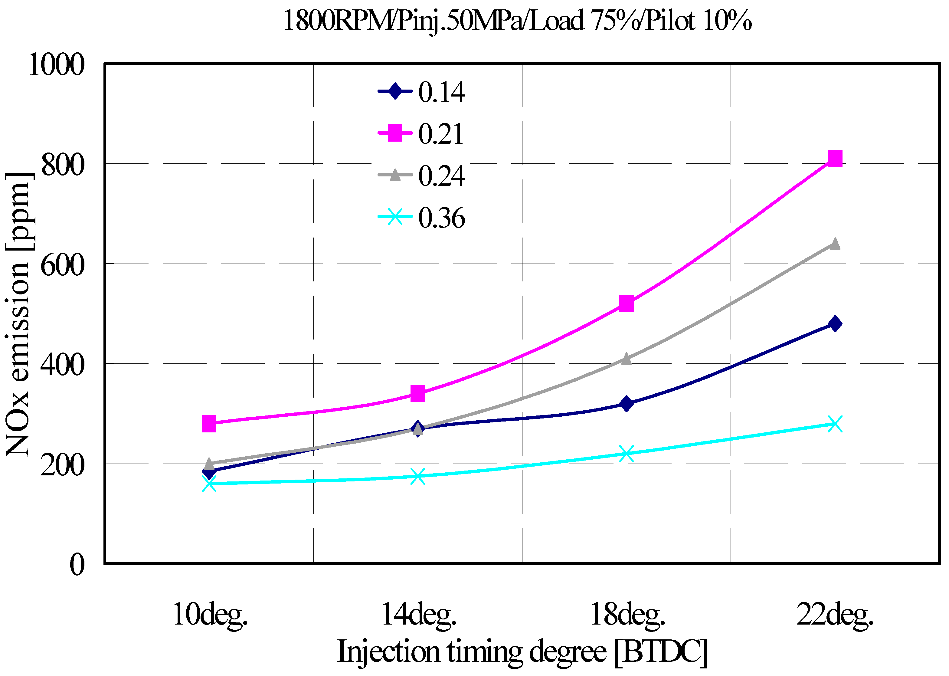
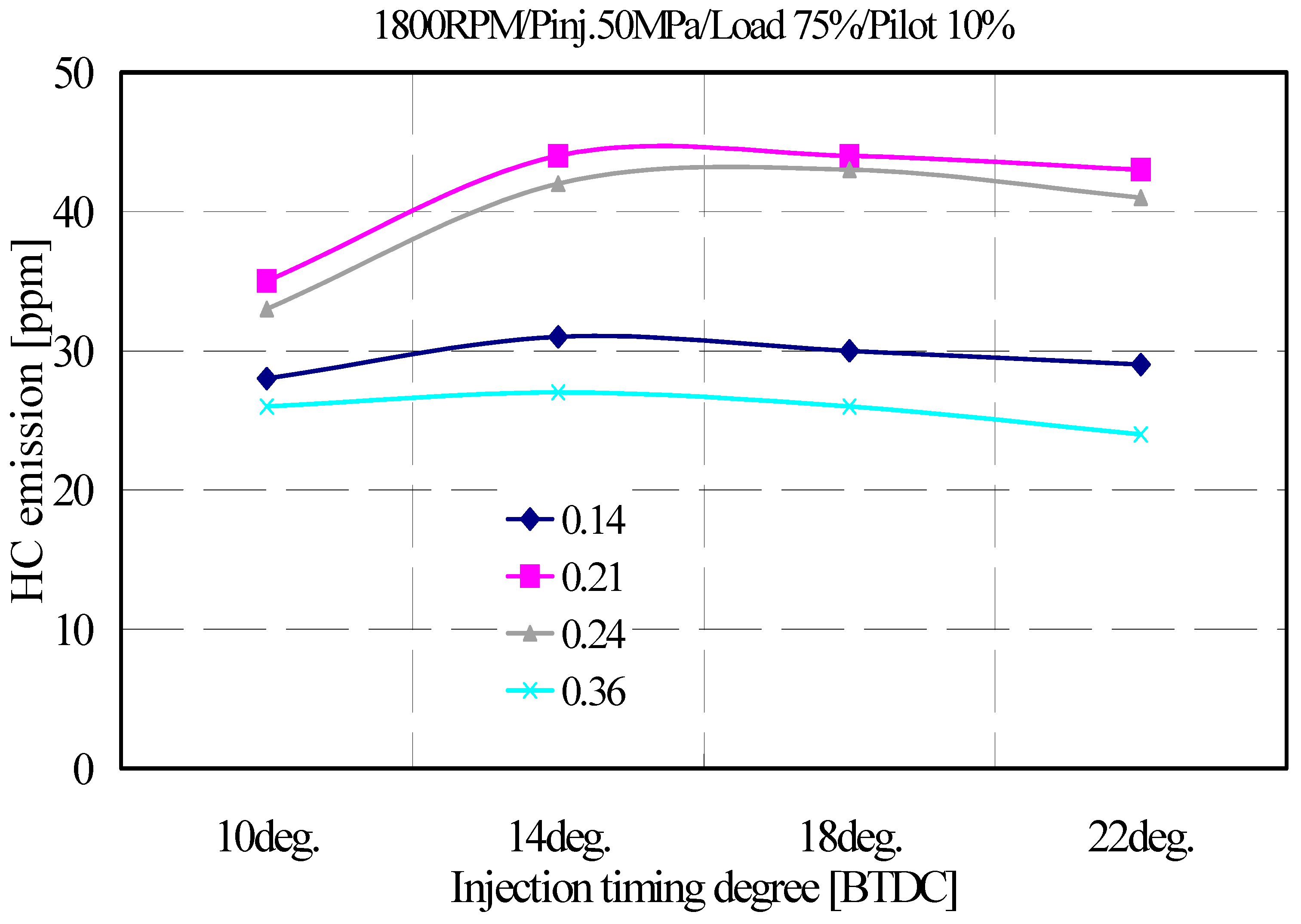
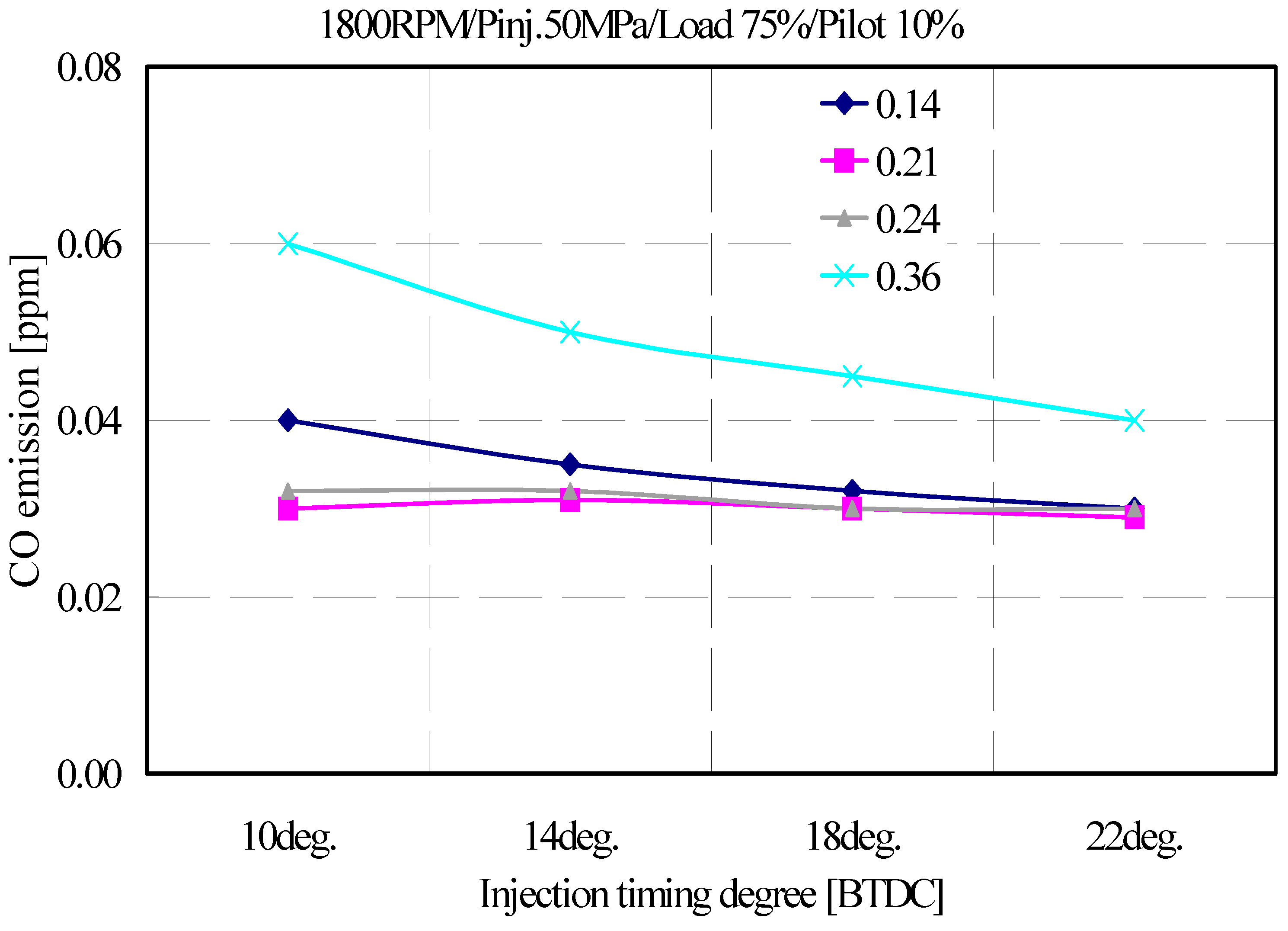
3.5. Effects of Needle Lift on Exhaust Gas According to Injection Timing in DME Engines

Figure 15, Figure 16 and Figure 17 show the exhaust gas rates (HC, NOx, and CO) for the engine performance tests. In this experiment, the exhaust gas characteristics were examined by applying the DLL-AP type needle lift of 0.14, 0.21, 0.24, and 0.36 mm nozzle (DL-AP type), which was one of the injector improvements, different from the examination result by the condition change of the ECU program.
1. NOx emission characteristics of DME engines depending on the injection timing and needle lift
Figure 15 shows the effect of needle lift on NOx emissions with injection timing at a loading rate of 75% at an injection pressure of 50 MPa. In this case, the effect of the needle lift on the NOx emission was found to increase as the injection timing was delayed and decreased as the injection angle was advanced. Further, the needle lifts showed low values at 0.36 and 0.14 mm, while at 0.21 and 0.24 mm showed an increasing trend. First, the increase in the injection timing was caused by the temperature rise of the combustion chamber because of diffusion combustion from the delay of the injection period. The decrease of 0.14 and 0.36 mm of needle lift at 22° BTDC caused incomplete combustion at 0.14 mm due to the long supply period because of the common rail characteristics for the required fuel supply when injected with the required injection period.
2. HC emission characteristics of DME engines depending on the injection timing and needle lift
Figure 16 shows the effect of needle lift on HC emissions with injection timing at a loading rate of 75% at an injection pressure of 50 MPa. In this case, the HC emission fluctuation was not large with different injection timing delays. The 0.36 mm needle lift showed a HC emission concentration lower than 0.21 mm, suggesting that the DME supply per unit time was oversupplied to the engine. Thus, the needle lift of 0.21 mm was useful for engine gas; however, it was not good in terms of exhaust gas.
3. CO emission characteristics of DME engines depending on the injection timing and needle lift
Figure 17 shows the effect of needle lift on CO emissions with injection timing at a loading rate of 75% at an injection pressure of 50 MPa. The CO emission slightly fluctuated at 0.36 mm because of the injection timing delay; however, there was no large fluctuation. This was expected to be incomplete combustion because of the longer injection period caused by the injection timing delay, as in the case of HC.

4. Conclusions

Based on the results of this study on diesel and DME engines with common rail conditions applied, we examined the engine performance changes and emission characteristics of exhaust gases with varying injection pressure and injection rate. The emission characteristics of NOx, HC, and CO were investigated for different injection pressures of the pilot injection. The exhaust gas emission characteristics for the pilot injection period and needle lift were investigated as follows:
  • For DME engines, the effect of fuel injection pressure on HC emissions was not significant at low speeds; however, at high speeds, higher fuel injection pressures caused lower HC emissions. To optimize the DME engine, it is necessary to optimize the fuel injection pressure and injection amount depending on the engine operating conditions.
  • The emission characteristics of CO were similar to those of HC. The CO emission concentration of DME engines was slightly lower than that of diesel engines. The fuel injection pressure did not have a significant effect at all operating conditions. This was because the combustion characteristics of the oxygenate fuel of DME described in HC. As the liquid fuel DME, which is a compressible oxygen fuel, was injected at high pressure, the mixing ratio with air was improved in the injection characteristic as compared to that with diesel. Further, it was expected to enhance into a diffusive combustion state.
  • The HC emission can be extremely low, as it was generated by oxygen deficiency in a state where the combustion chamber wall surface or the air–fuel ratio was rich, and because DME was generated in a state where the fuel was not vaporized and the oxidized fuel was an oxygen fuel. Moreover, as the injection pressure increased, the emission rate of NOx reduced. This was because the injection rate in diesel and DME engines was optimized according to the injection period, and incomplete combustion is not expected.
  • The NOx emission was reduced at the injection pressure of 50 MPa, with pilot injection rate increasing from 0% to 30% of the total injected amount, and the minimum and maximum injection timing being 10° and 22° BTDC, respectively. The NOx emission decreased with the increasing pilot injection rate because the pilot injection before the main injection delays the rapid diffusion combustion. This was because the injection period delay lowered the combustion chamber temperature; and it was considered that NOx emissions generated at a high temperature were reduced because the average effective pressure caused by the injection delay decreased.
  • It can be seen from this experiment that NOx and HC were opposite to each other. Further, as the pilot injection amount increased, or as it got closer to TDC, the HC emission amount increased. When pilot injection was applied in this study, it was expected that the injection period would be delayed if more than 10% was applied, so that the HC emissions would increase because of unstable combustion.
  • The increase in injection timing was caused by the delay in injection period, occurring with the temperature rise in the combustion chamber because of diffusive combustion. The decrease of 0.14 mm and 0.36 mm of needle lift at 22° BTDC was caused by incomplete combustion because of the longer supply period of the characteristics of common rail for supplying the required fuel when injected with the required injection period at 0.14 mm.

Author Contributions

S.Y. and C.L. conceived and designed the experiments; S.Y. performed the experiments; C.L. analyzed the data; S.Y. contributed reagents/materials/analysis tools; C.L. wrote the paper.

Funding

This study was supported by the development of key fusion technology of the industry–academia research cooperation cluster support project.

Conflicts of Interest

The authors declare no conflict of interest.

References

  1. Lázaro, L.; Aparecida, C.; Lacava, P. Strategies for emission control in diesel engine to meet Euro VI. Fuel 2013, 104, 183–193. [Google Scholar]
  2. Miller, B. Fossil Fuel Emissions Control Technologies; Butterworth Heinemann: Oxford, UK, 2015. [Google Scholar]
  3. Thangaraja, J.; Kannan, C. Effect of exhaust gas recirculation on advanced diesel combustion and alternate fuels: A review. Appl. Energy 2016, 180, 169–184. [Google Scholar] [CrossRef]
  4. Khair, M. Technical and Synergistic Approaches towards the Twenty-First Century Diesel Engine; SAE Technical Paper 972687; SAE International: Warrendale, PA, USA, 1997. [Google Scholar]
  5. Digiulio, C.; Pihl, J.; Choi, J.; Parks, J.; Lance, M.; Toops, T.; Amiridis, M.D. NH3 formation over a lean NOX Trap (LNT) system: Effects of lean/rich cycle timing and temperature. Appl. Catal. B 2014, 147, 698–710. [Google Scholar] [CrossRef]
  6. Elnajjar, E.; Mohammad, O.; Mohamed, S. Experimental investigation of dual engine performance using variable LPG composition fuel. Renew. Energy 2013, 56, 110–116. [Google Scholar] [CrossRef]
  7. Kalghatgi, G.T.; Hildingsson, L.; Harrison, A.J.; Johansson, B. Auto ignition quality of gasoline fuels in partially premixed combustion in diesel engines. Proc. Combust. Inst. 2011, 33, 3015–3021. [Google Scholar] [CrossRef]
  8. Kim, H.M.; Kim, Y.J.; Lee, K.H. A study of the characteristics of mixture formation and combustion in a PCCI engine using an early multiple injection strategy. Energy Fuels 2008, 22, 1542–1548. [Google Scholar] [CrossRef]
  9. Kiplimo, R.; Tomita, E.; Kawahara, N.; Yokobe, S. Effects of spray impingement, injection parameters, and EGR on the combustion and emission characteristics of a PCCI diesel engine. Appl. Therm. Eng. 2012, 37, 165–175. [Google Scholar] [CrossRef]
  10. Abdelaal, M.M.; Hegab, A.H. Combustion and emission characteristics of a natural gas-fueled diesel engine with EGR. Energy Convers. Manag. 2012, 64, 301–312. [Google Scholar] [CrossRef]
  11. Kumaraswamy, A.; Durga Prasad, B. Performance analysis of a dual fuel engine using LPG and diesel with EGR system. Proc. Eng. 2012, 38, 2784–2792. [Google Scholar] [CrossRef]
  12. Hosseinzadeh, A.; Saray, R.K.; Mahmoudi, S.S. Comparison of thermal, radical and chemical effects of EGR gases using availability analysis in dual-fuel engines at part loads. Energy Convers. Manag. 2010, 51, 2321–2329. [Google Scholar] [CrossRef]
  13. Lee, K.; Lee, C. An Experimental Study of the Extent of the Operating Region and Emission Characteristics of Stratified Combustion Using the Controlled Autoignition Method. Energy Fuels 2006, 20, 1862–1869. [Google Scholar] [CrossRef]
  14. Lee, C.; Tomita, E.; Lee, K. Characteristics of Combustion Stability and Emission in SCCI and CAI Combustion Based on Direct-Injection Gasoline Engine; SAE Technical Paper 2007-01-1872; SAE International: Warrendale, PA, USA, 2007. [Google Scholar]
  15. Lee, C.H.; Lee, K.H. An Experimental Study on the Combustion and Emission Characteristics of a Stratified Charge Compression Ignition (SCCI) Engine. Energy Fuels 2007, 21, 1901–1907. [Google Scholar] [CrossRef]
  16. Lee, C.-H.; Lee, K.-H.; Lim, K.-B. An Experimental Study on the Combustion and Emission Characteristics According to the Variation of Compression Ratio and Intake Temperature Using Stratified Charge Compression Ignition in a Gasoline Direct Injection Engine. Trans. Korean Soc. Mech. Eng. B 2006, 30, 538–545. [Google Scholar] [CrossRef]
  17. Lee, S.; Oh, S.; Choi, Y. Performance and emission characteristics of an SI engine operated with DME blended LPG fuel. Fuel 2009, 88, 1009–1015. [Google Scholar] [CrossRef]
  18. Park, S. Optimization of combustion chamber geometry and engine conditioned for compression ignition engines fueled with dimethyl ether. Fuel 2012, 97, 61–71. [Google Scholar] [CrossRef]
  19. Yeom, K.; Bae, C. Knock characteristics in liquefied petroleum gas (LPG) = dimethyl ether (DME) and gasoline–DME homogeneous charge compression ignition engines. Energy Fuels 2009, 23, 1956–1964. [Google Scholar] [CrossRef]
  20. Park, S. Numerical study on optimal operating conditions of homogeneous charge compression ignition engines. Energy Fuels 2009, 23, 2909–2918. [Google Scholar]
  21. Zhou, L.B.; Wang, H.W.; Jiang, D.M.; Huang, Z. Study of Performance and Combustion Characteristics of a DME Fuelled Light-Duty Direct Injection Diesel Engine; SAE Paper 1999; SAE International: Warrendale, PA, USA, 1999. [Google Scholar]
  22. Fleisch, T.; McCarthy, C.; Basu, A. A new clean diesel technology: Demonstration of ULEV emissions on a Navistar diesel engine fuelled with dimethyl ether. J. Fuels Lubr. 1995, 104, 42–53. [Google Scholar]
  23. Clausen, L.R.; Elmegaard, B.; Houbak, N. Design of Novel DME/Methanol Synthesis Plants Based on Gasification of Biomass; DCAMM Special Report, No. S123; Technical University of Denmark (DTU): Lyngby, Denmark, 2011. [Google Scholar]
  24. Ying, W.; Li, H.; Jie, Z.; Longbao, Z. Study of HCCI–DI combustion and emissions in a DME engine. Fuel 2009, 88, 2255–2261. [Google Scholar] [CrossRef]
  25. Xinling, L.; Zhen, H. Emission reduction potential of using gas-to-liquid and dimethyl ether fuels on a turbocharged diesel engine. Sci. Total Environ. 2009, 407, 2234–2244. [Google Scholar] [CrossRef]
  26. Junjun, Z.; Xinqi, Q.; Zhen, W.; Bin, G.; Zhen, H. Experimental investigation of low-temperature combustion (LTC) in an engine fuelled with dimethyl ether (DME). Energy Fuels 2009, 23, 170–174. [Google Scholar] [CrossRef]
  27. Jang, J.; Bae, C. Effects of valve events on the engine efficiency in a homogeneous charge compression ignition engine fuelled by dimethyl ether. Fuel 2009, 88, 1228–1234. [Google Scholar] [CrossRef]
  28. AVL. AVL Global Emission Legislation Report 2011. Available online: https://www.avl.com/web/guest/avl-focus-2011 (accessed on 13 February 2019).
  29. Park, S.H.; Lee, C.S. Combustion performance and emission reduction characteristics of automotive DME engine system. Prog. Energy Combust. Sci. 2013, 39, 147–168. [Google Scholar] [CrossRef]
  30. Fonseca de Carvalho e Silva, D. DME as Alternative Diesel Fuel: Overview; SAE Paper 2006-01-2916; SAE International: Warrendale, PA, USA, 2006. [Google Scholar]
  31. Song, J.; Huang, Z.; Qiao, X.Q.; Wang, W.L. Performance of a controllable premixed combustion engine fueled with dimethyl ether. Energy Convers. Manag. 2004, 45, 2223–2232. [Google Scholar] [CrossRef]
  32. Fischer, S.L.; Dryer, F.L.; Curran, H.J. The Reaction Kinetics of Dimethyl Ether. I: High-Temperature Prolysis and Oxidation in Flow Reactors. Int. J. Chem. Kinet. 2000, 32, 713–740. [Google Scholar] [CrossRef]
  33. Curran, H.J.; Fischer, S.L.; Dryer, F.L. The Reaction Kinetics of Dimethyl Ether. II: Low-Temperature Oxidation in Flow Reactors. Int. J. Chem. Kinet. 2000, 32, 741–789. [Google Scholar] [CrossRef]
  34. Teng, H.; McCandless, J.C.; Schneyer, B. Thermodynamic Properties of Dimethyl Ether—An Alternative Fuel for Compression-Ignition Engines; SAE Paper 2004-01-0093; SAE International: Warrendale, PA, USA, 2004. [Google Scholar]
  35. How, H.G.; Masjuki, H.H.; Kalam, M.A.; Teoh, Y.H. Influence of injection timing and split injection strategies on performance, emissions, and combustion characteristics of diesel engine fueled with biodiesel blended fuels. Fuel 2018, 213, 106–114. [Google Scholar] [CrossRef]
  36. Jain, A.; Singh, A.P.; Agarwal, A.K. Effect of split fuel injection and EGR on NOx and PM emission reduction in a low temperature combustion (LTC) mode diesel engine. Energy 2017, 122, 249–264. [Google Scholar] [CrossRef]
  37. Guardiola, C.; Martín, J.; Pla, B.; Bares, P. Cycle by cycle NOx model for diesel engine control. Appl. Therm. Eng. 2017, 110, 1011–1020. [Google Scholar] [CrossRef]
  38. Corsini, A.; Fanfarillo, G.; Rispoli, F.; Venturini, P. Pollutant Emissions in Common-rail Diesel Engines in Extraurban Cycle: Rapeseed Oils vs Diesel Fuel. Energy Procedia 2015, 82, 141–148. [Google Scholar] [CrossRef] [Green Version]
  39. Lee, C.; Chung, J.; Lee, K. Emission Characteristics for a Homogeneous Charged Compression Ignition Diesel Engine with Exhaust Gas Recirculation Using Split Injection Methodology. Energies 2017, 10, 2146. [Google Scholar] [CrossRef]
  40. Watanabe, H.; Tahara, T.; Tamanouchi, M.; Iida, J. Study of the effects on exhaust emissions in direct injection diesel engines: Effects of fuel injection system, distillation properties and cetane number. JSAE Rev. 1998, 19, 21–26. [Google Scholar] [CrossRef]
  41. Cédric, L.; Goriaux, M.; Tassel, P.; Perret, P.; Liu, Y. Impact of Aftertreatment Device and Driving Conditions on Black Carbon, Ultrafine Particle and NOx Emissions for Euro 5 Diesel and Gasoline Vehicles. Transp. Res. Procedia 2016, 14, 3079–3088. [Google Scholar] [CrossRef] [Green Version]
  42. Twigg, M.V. Advanced integrated exhaust aftertreatment systems and the mechanisms of NOx emissions control. In Proceedings of the Internal Combustion Engines: Performance, Fuel Economy and Emissions IMechE, London, UK, 27–28 November 2013; pp. 219–229. [Google Scholar]
  43. Cordiner, S.; Mulone, V.; Nobile, M.; Rocco, V. Impact of biodiesel fuel on engine emissions and Aftertreatment System operation. Appl. Energy 2016, 164, 972–983. [Google Scholar] [CrossRef]
  44. Lee, C. Numerical and experimental investigation of evaporation and mixture uniformity of urea–water solution in selective catalytic reduction system. Transp. Res. Part D Transp. Environ. 2018, 60, 210–224. [Google Scholar] [CrossRef]
  45. Lee, C. Modeling urea-selective catalyst reduction with vanadium catalyst based on NH3 temperature programming desorption experiment. Fuel 2016, 173, 155–163. [Google Scholar] [CrossRef]
  46. Winkel, A.; Mosquera, J.; Aarnink, A.J.A.; Koerkamp, P.W.G.G.; Ogink, N.W.M. Evaluation of oil spraying systems and air ionisation systems for abatement of particulate matter emission in commercial poultry houses. Biosyst. Eng. 2016, 150, 104–122. [Google Scholar] [CrossRef]
  47. Hamid, M.F.; Idroas, M.Y.; Sa’add, S.; Bahri, A.J.S.; Zainal, Z.A. Numerical investigation of in-cylinder air flow characteristic improvement for Emulsified biofuel (EB) application. Renew. Energy 2018, 127, 84–93. [Google Scholar] [CrossRef]
  48. Yoon, S.H.; Kim, H.J.; Park, S. Study on optimal combustion strategy to improve combustion performance in a single-cylinder PCCI diesel engine with different combustion chamber geometry. Appl. Therm. Eng. 2018, 144, 1081–1090. [Google Scholar] [CrossRef]
  49. Li, X.-R.; Yang, W.; Su, L.-W.; Liu, F.-S. Mixing and combustion mechanisms within lateral swirl combustion system (LSCS) in a DI diesel engine. Appl. Therm. Eng. 2017, 123, 7–18. [Google Scholar] [CrossRef]
  50. Lee, C.H.; Lee, K.H. An experimental study of the combustion characteristics in SCCI and CAI based ondirect-injection gasoline engine. Exp. Therm. Fluid Sci. 2007, 31, 1121–1132. [Google Scholar] [CrossRef]
  51. Lee, C.; Lee, K. An experimental study on the flow and mixture distribution in a visualization engine using digital particle image velocimetry and entropy analysis. Int. J. Automot. Technol. 2007, 8, 127–135. [Google Scholar]
  52. Reitz, R.D.; Duraisamy, G. Review of high efficiency and clean reactivity controlled compression ignition (RCCI) combustion in internal combustion engines. Prog. Energy Combust. Sci. 2015, 46, 12–71. [Google Scholar] [CrossRef] [Green Version]
  53. Tan, P.; Li, Y.; Shen, H. Effect of lubricant sulfur on the morphology and elemental composition of diesel exhaust particles. J. Environ. Sci. 2017, 55, 354–362. [Google Scholar] [CrossRef] [PubMed]
  54. Hori, S.; Sato, T.; Narusawa, K. Effects of diesel fuel composition on SOF and PAH exhaust emissions. JSAE Rev. 1997, 18, 255–261. [Google Scholar] [CrossRef]
  55. Zhu, L.; Zhang, W.; Liu, W.; Huang, Z. Experimental study on particulate and NOx emissions of a diesel engine fueled with ultra-low sulfur diesel, RME-diesel blends and PME-diesel blends. Sci. Total Environ. 2010, 408, 1050–1058. [Google Scholar] [CrossRef] [PubMed]
  56. Gelso, E.R.; Dahl, J. Diesel Engine Control with Exhaust Aftertreatment Constraints. IFAC-PapersOnLine 2017, 50, 8921–8926. [Google Scholar] [CrossRef]
  57. Reijnders, J.; Boot, M.; de Goey, P. Particle nucleation-accumulation mode trade-off: A second diesel dilemma? J. Aerosol Sci. 2018, 124, 95–111. [Google Scholar] [CrossRef]
  58. Alam, M.; Fujita, O.; Ito, K.; Kajitani, S.; Oguma, M.; Machida, H. Comparison of NOx Reduction Performance with NOx Catalyst in Simulated Gas and Actual DME Engine Exhaust Gas. J. Power Energy 2004, 218, 89–95. [Google Scholar] [CrossRef]
  59. Cipolat, D. DME as a Fuel for Compression Ignition Engines; SAE Technical Paper 2001-24-0039; SAE International: Warrendale, PA, USA, 2001. [Google Scholar]
  60. Mizusawa, K.; Katoh, K.; Hamaguchi, S.; Hayashi, H.; Hocho, S. Development of Air Fuel Ratio Sensor for 1997 Model Year LEV Vehicle; SAE Technical Paper 970843; SAE International: Warrendale, PA, USA, 1997. [Google Scholar]
Figure 1. Schematic diagram of the liquid fuel supply system.
Applsci 09 00647 g001
Figure 2. Schematic diagram of the fuel injection control system.
Applsci 09 00647 g002
Figure 3. Effects of injection pressure on the exhaust gas.
Applsci 09 00647 g003
Figure 4. NOx emission characteristics of diesel and DME engines without pilot injection as a function of injection pressure and engine speed.
Applsci 09 00647 g004
Figure 5. HC emission characteristics of diesel and DME engines without pilot injection as a function of injection pressure and engine speed.
Applsci 09 00647 g005
Figure 6. CO emission characteristics of diesel and DME engines without pilot injection as a function of injection pressure and engine speed.
Applsci 09 00647 g006
Figure 7. Smoke characteristics of diesel and DME engines without pilot injection as a function of injection pressure and engine speed.
Applsci 09 00647 g007
Figure 8. NOx emission characteristics of diesel and DME engines with and without pilot injection as a function of injection pressure.
Applsci 09 00647 g008
Figure 9. HC emission characteristics of diesel and DME engines with and without pilot injection as a function of injection pressure.
Applsci 09 00647 g009
Figure 10. CO emission characteristics of diesel and DME engines with and without pilot injection as a function of injection pressure.
Applsci 09 00647 g010
Figure 11. NOx emission characteristics of DME engines with the pilot injection duration rate as a function of injection timing.
Applsci 09 00647 g011
Figure 12. HC emission characteristics of DME engines with the pilot injection duration rate as a function of injection timing.
Applsci 09 00647 g012
Figure 13. CO emission characteristics of DME engines with the pilot injection duration rate as a function of injection timing.
Applsci 09 00647 g013
Figure 14. CO2 emission characteristics of DME engines with the pilot injection duration rate as a function of injection timing.
Applsci 09 00647 g014
Figure 15. NOx emission characteristics of DME engines with nozzle needle lift as a function of injection timing degree.
Applsci 09 00647 g015
Figure 16. HC emission characteristic of DME engines with nozzle needle lift as a function of injection timing degree.
Applsci 09 00647 g016
Figure 17. CO emission characteristics of DME engines with nozzle needle lift as a function of injection timing degree.
Applsci 09 00647 g017
Table 1. Engine specifications in this study.
ItemsSpecifications
Cycle4
Combustion TypeCI
Compression Ratio18
Displacement (ℓ)0.673
Bore × Stroke (mm × mm)95 × 95
Max. Power (kW/rpm)9.11/2200
Max. Torque (kg m)4.22
Table 2. Causes of PM and NOx generation and mitigation measures.
EmissionMethodsEffects of Reduction
NOxInjection timing delayLowering of combustion temperature [35]
Exhaust gas recirculationLowering of combustion temperature [36]
Lowering of oxygen thickness [37]
Water fulminationLowering of combustion temperature [38]
Fuel–water injection
Pilot injectionLowering of combustion rate in the first period [39]
Improving cetane numberLowering of combustion rate in the first period [40]
After treatmentNOx recharge and resolve [41,42,43,44,45]
PMSpray improvementAir inhalation increase in spray [46]
Mixing increase [47]
Optimization in combustion chamberMixing increase [48]
Increase in air usage rate [49]
Confusion combustionMixing increase [50]
Increase of smoke oxidation [51]
Turbo chargingLean burn combustion [52]
Air inhalation increase in spray [52]
Reduction in oil consumptionReduction of SOF [53]
Low sulfur fuelReduction of sulfur combination matter [53,54,55]
After treatmentSmoke catching and SOF oxidation [56,57]

