Article

High-Gain Waveguide-Fed Circularly Polarized Spidron Fractal Aperture Antenna

1
Department of Electrical and Computer Engineering, Sungkyunkwan University, Suwon 440-746, Korea
2
Department of Electronics Computer Engineering, Hanyang University, Seoul 133-971, Korea
*
Author to whom correspondence should be addressed.
Appl. Sci. 2019, 9(4), 691; https://doi.org/10.3390/app9040691
Submission received: 21 January 2019 / Revised: 12 February 2019 / Accepted: 15 February 2019 / Published: 18 February 2019
(This article belongs to the Section Electrical, Electronics and Communications Engineering)

Abstract

:
A high-gain rectangular waveguide-fed aperture antenna that uses a Spidron fractal structure to produce circular polarization is proposed. The antenna consists of a Spidron fractal aperture etched onto the ground plane of a dielectric substrate that is directly excited by a WR (Waveguide Rectangular)-90 waveguide-to-coax adapter. A superstrate was implemented at an appropriate distance above the antenna to enhance the broadside gain significantly. An antenna prototype was fabricated and tested to validate the design. The measured impedance bandwidth for | S 11 | ≤ −10 dB is 9.89–11.58 GHz (15.74%). The corresponding measured 3 dB axial ratio (AR) bandwidth is 10.68–11.00 GHz (2.95%), and within the measured 3 dB AR bandwidth, a maximum realized gain of 9.59 dBic is achieved. The radiation patterns of the proposed antenna are presented and discussed.

1. Introduction

Rectangular aperture antennas with a waveguide feeder are widely utilized in satellite communications and radar systems. These antennas can be flush-mounted onto the surfaces of aircraft or spacecraft, and their openings can be covered with a dielectric material to prevent exposure to environmental conditions that would otherwise cause them damage. It has been found [1] that instead of using an open-ended waveguide, resonant apertures should be used to attain a lower reflection coefficient. Among the currently available resonant apertures, the fractal aperture is a good candidate. With space-filling and self-similarity properties, fractal geometries have been applied extensively in antenna engineering [2,3]. Therefore, fractal aperture antennas with a waveguide feeder have also attracted much attention [4]. However, the waveguide-fed fractal aperture antennas reported in earlier work [4] are mostly linearly polarized antennas. In most practical satellite communications and radar systems, circularly polarized (CP) antennas are preferred for their ability to alleviate multipath and fading effects and to provide a more flexible orientation between RF (Radio Frequency) transmitting and receiving antennas [5,6,7,8,9]. Therefore, it is of interest to design waveguide-fed fractal aperture antennas with circular polarization.
Moreover, antennas with high-gain characteristics are desirable for wireless communications over longer distances. A very simple method for achieving high-gain performance is the placement of a superstrate over an antenna [10,11,12]. By properly choosing the distance between the superstrate and the antenna and by carefully specifying the thickness of the superstrate, a very high gain can be attained. In addition, a superstrate with multilayer dielectric slabs separated by air gaps of approximately one-quarter of a wavelength was also investigated [12], but the prototype of this design was very bulky in size.
In this paper, we propose the design of a rectangular waveguide-fed fractal aperture CP antenna with high-gain characteristics. In the design, two Spidron fractal slots are merged to form a Spidron fractal aperture to realize circular polarization operation. To improve the broadside gain, a single-layer dielectric substrate that acts as a superstrate is placed over the antenna at an appropriate distance. As a result, an enhancement of more than 5.4 dBic in the broadside gain is achieved. The results of the simulation were verified by measurements, and the proposed rectangular waveguide-fed Spidron fractal antenna with the superstrate exhibits CP operation of around 10.85 GHz with a maximum realized gain of 9.59 dBic. Details of the antenna design and the experimental results are presented and discussed in the following sections.

2. Antenna Design

Figure 1 presents the geometry of the proposed antenna, with Figure 1a showing an exploded three-dimensional (3-D) view. The antenna includes a Taconic RF-35 dielectric substrate ( h s u b = 0.51 mm, ε r = 3.5, and tan δ = 0.0018), a ground plane mounted on the bottom layer of the dielectric substrate, a superstrate, and a WR-90 waveguide-to-coax adapter. The superstrate is a Rogers RT/duroid 6010 material ( h s u p = 0.64 mm, ε r = 10.2, and tan δ = 0.0023). The Spidron fractal aperture is etched on the ground plane of the dielectric substrate. The dimensions of the substrate and the superstrate with four truncated corners are identical to those of the flange of the adapter, and these components can also serve as radome layers to protect the antenna aperture. The substrate is directly attached to the flange, and the superstrate is located above the ground plane at a distance of S (see Figure 1b).
The Spidron fractal structure was initially utilized in the design of a wideband CP slot antenna [13]. In subsequent works [14,15], a dual-band CP patch antenna and a wideband CP dielectric resonator antenna with Spidron fractal geometry were successfully designed. In the design proposed here, a Spidron fractal system with nine iterations is implemented. As shown in Figure 1c, the proposed Spidron fractal aperture is formed by merging two nine-iterated Spidron fractal slots (here, Spidron fractal slot #1 and Spidron fractal slot #2). These two Spidron fractal slots share a common edge, as indicated by the dashed line (see Figure 1c). The Spidron fractal aperture is positioned such that vertex A of Spidron fractal slot #2 is located at the position of ( d x , d y ) with respect to the global coordinate system. A simulation of the antenna was conducted using the ANSYS HFSS simulation software (ANSYS, Inc. Canonsburg, PA, USA). The proposed antenna was optimized to achieve right-handed circular polarization (RHCP) around the designed frequency of 11.1 GHz. The optimized dimensional parameters are given in Table 1.

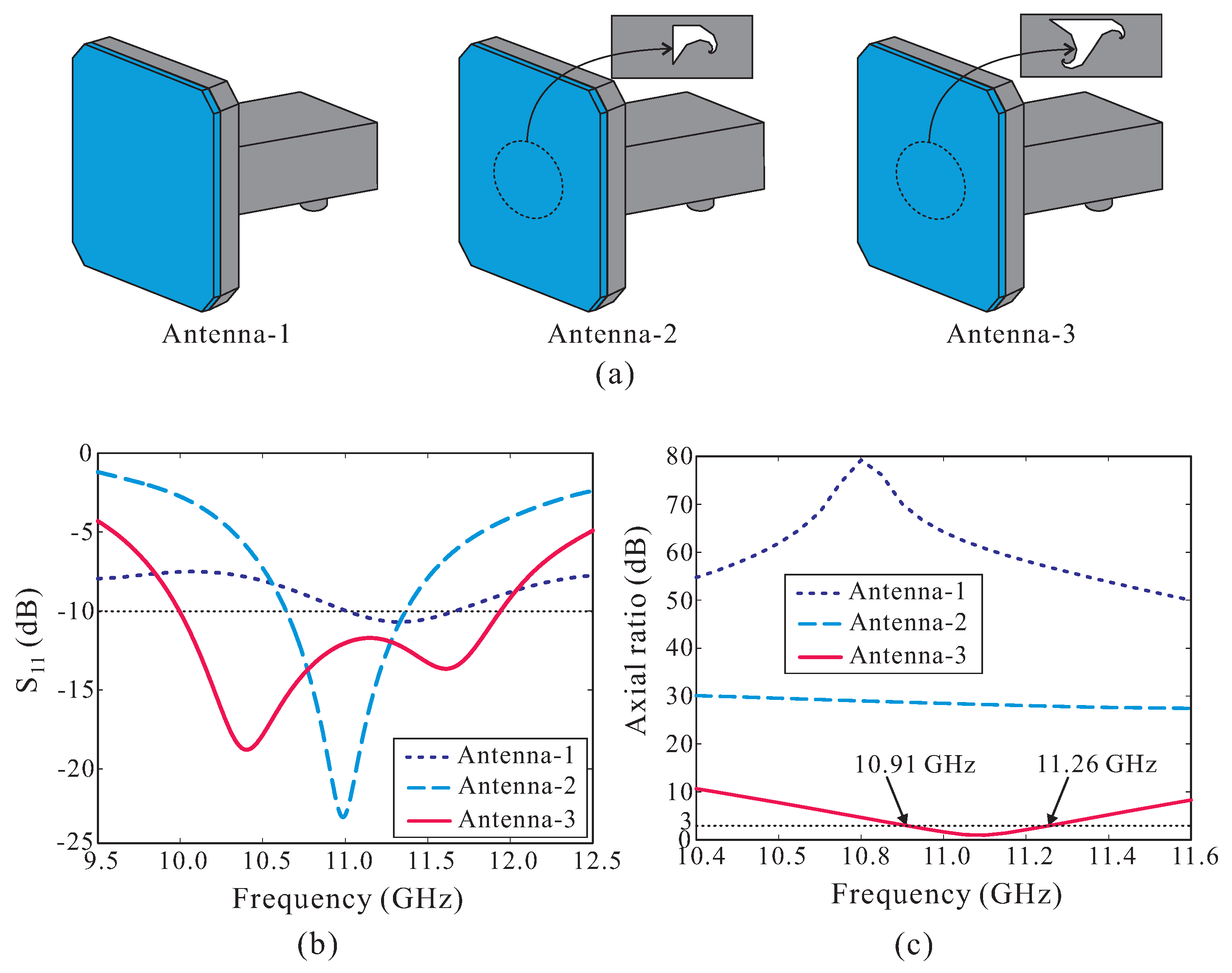
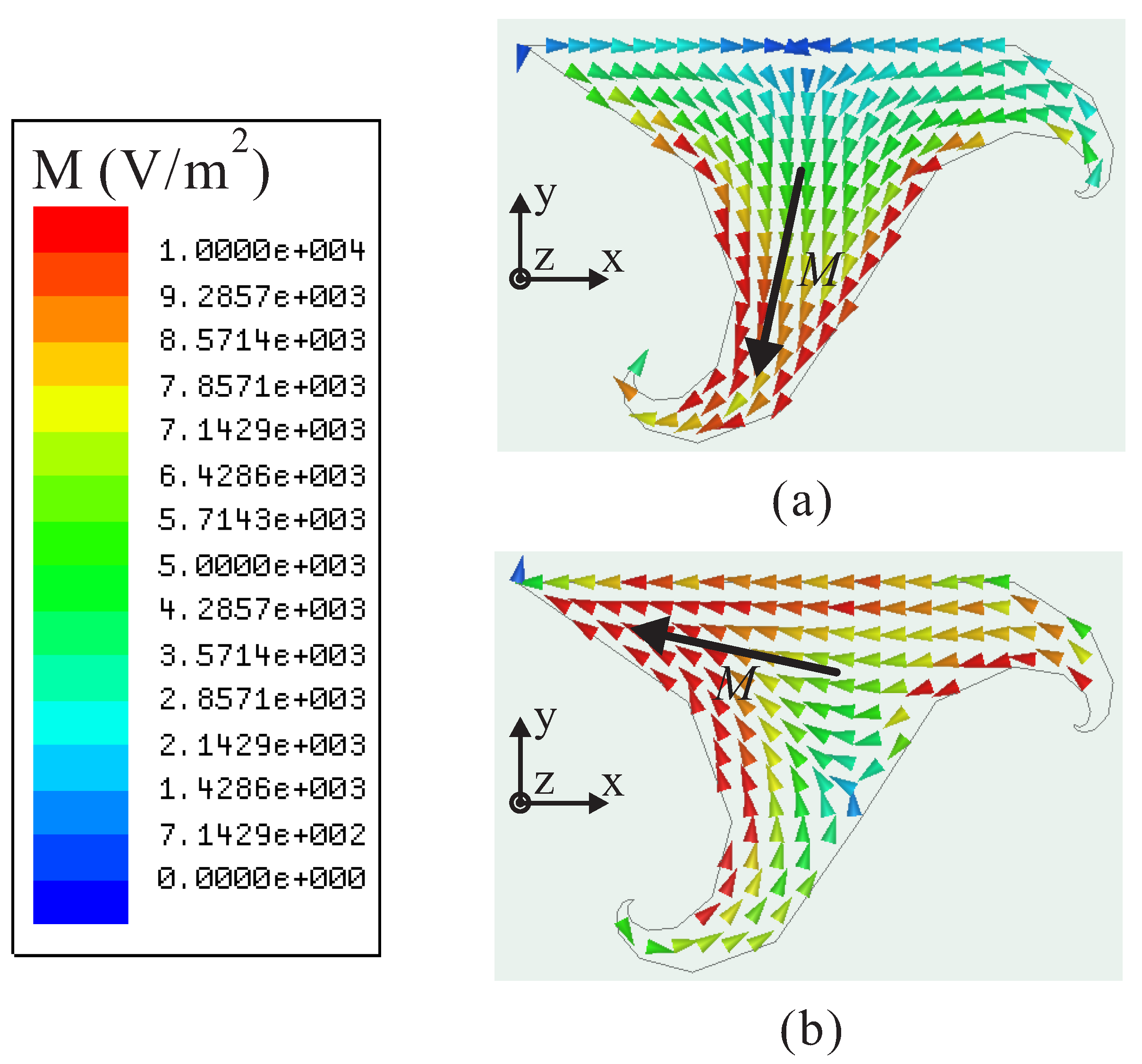
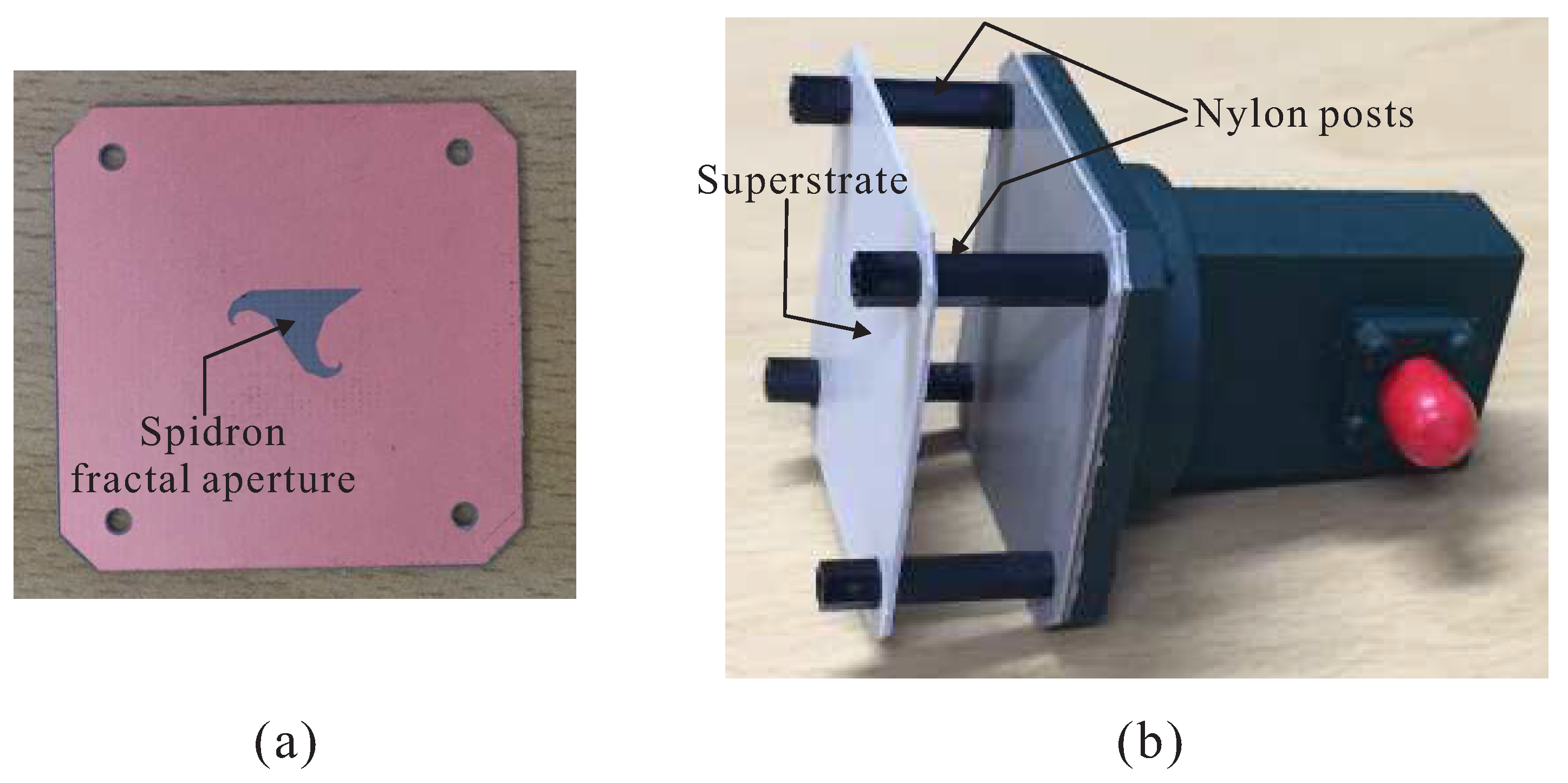
2.1. Design of the Rectangular Waveguide-Fed CP Spidron Fractal Aperture Antenna

Figure 2a presents the design process of the rectangular waveguide-fed antennas, i.e., without a superstrate. First, Antenna-1 was designed by simply covering an open-ended waveguide with a single dielectric layer. Subsequently, instead of using the open-ended waveguide, fractal apertures were applied, forming Antenna-2 and Antenna-3. In Antenna-2, the fractal aperture is realized with only one Spidron fractal slot. Meanwhile, in Antenna-3, two Spidron fractal slots are merged to form the fractal aperture. The simulated results of the reflection coefficients and axial ratios (ARs) of all three antennas are plotted in Figure 2b,c. Clearly, Antenna-1 resonates at a frequency of approximately 11.35 GHz with a very high reflection coefficient of −10.7 dB, as Antenna-1 is basically an open-ended waveguide antenna which is covered by a single dielectric layer. In addition, Antenna-1 is a linearly polarized antenna. Given that it uses a fractal aperture, Antenna-2 has a single resonance at 11 GHz with a minimum reflection coefficient of −23 dB and a narrow bandwidth (see Figure 2b). However, as indicated in Figure 2c, Antenna-2 does not exhibit circular polarization operation. By properly merging two Spidron fractal slots to form the proposed Spidron fractal aperture, Antenna-3 generates two resonances at the frequencies of 10.35 GHz and 11.65 GHz. The two resonances are combined to realize a wide −10 dB reflection bandwidth of 10.00–11.94 GHz. Furthermore, Antenna-3 yields circular polarization operation with a 3 dB AR bandwidth of 10.91–11.26 GHz (see Figure 2c). This 3 dB AR bandwidth is entirely covered by the −10 dB reflection bandwidth. It is important to note that additional resonances can be realized to form a wider −10 dB reflection bandwidth by adding additional Spidron fractal slots and merging them. However, considering the given aperture areas of the rectangular waveguide, the aperture consisting of only two Spidron fractal slots is effectively excited by the rectangular waveguide. Therefore, two Spidron fractal slots were finally used to realize the proposed Spidron fractal aperture.
In order to demonstrate how circular polarization operation is realized, we investigated the time-varying magnetic current distributions on the proposed Spidron fractal aperture at 11.1 GHz. Figure 3 depicts the simulated magnetic current distributions observed from the + z -direction for t = 0 and t = T/4, where T is the period. At t = 0, the major currents are on Spidron fractal slot #1, and their vector sum ( M t o t a l ) is from the right-upper corner to the left-lower corner. Meanwhile, at t = T/4, the currents on Spidron fractal slot #2 dominate the radiation, exhibiting a vector sum ( M t o t a l ) from the left-upper corner to the right-lower corner. This vector is perpendicular to that at t = 0 and revolves in the counter-clockwise direction as the time t changes, hence generating RHCP in the + z -direction.

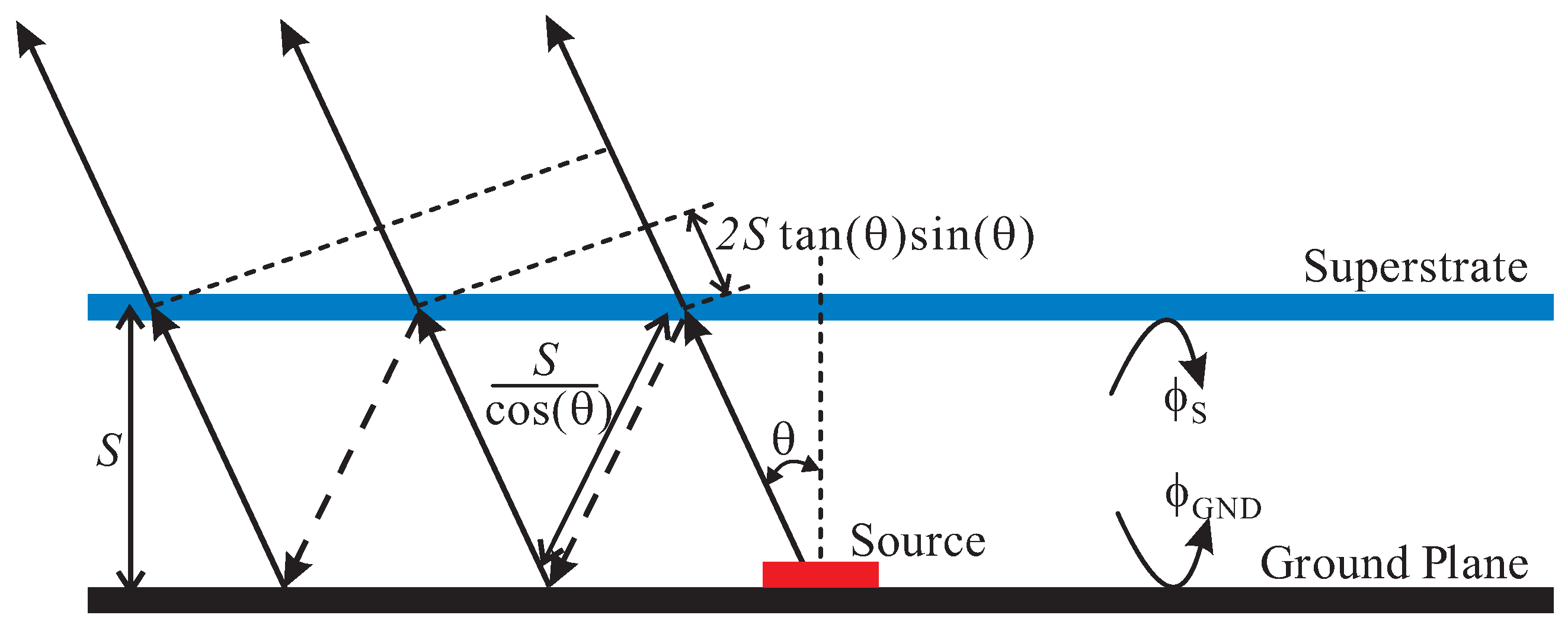
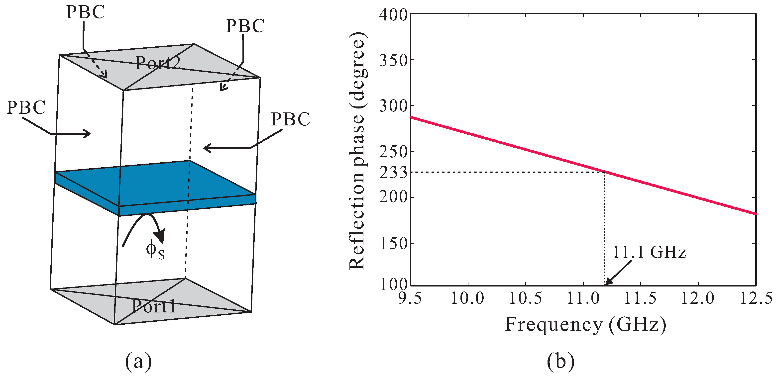
2.2. Design of the High-Gain Rectangular Waveguide-Fed CP Spidron Fractal Aperture Antenna

In this section, we present the design of a rectangular waveguide-fed CP Spidron fractal aperture antenna incorporated with a superstrate to achieve high gain performance. The operating principle of the superstrate with regard to gain enhancement can be briefly explained by considering the multiple reflections between the superstrate and the ground plane with the source, as shown in Figure 4. Assume that electromagnetic waves are emitted from the source at an incident angle of θ ; according to the ray tracking model [16,17], the phase difference Δ ϕ between two adjacent transmitted rays can be calculated as
Δ ϕ = ϕ S 2 π · 2 S λ cos ( θ ) + ϕ G N D ( 2 π λ · 2 S · tan ( θ ) sin ( θ ) )
where λ is the wavelength in free space at the designed frequency; ϕ S and ϕ G N D are the reflection phases of the superstrate and the ground plane, respectively; and S is the spacing between the superstrate and the ground plane.
To realize high gain in the θ direction, all transmitted rays should be in-phase, meaning that the phase difference Δ ϕ between two adjacent rays should be an integral multiple of 2 π . For most practical applications, antennas are required to have maximum gain at θ = 0 . Therefore, the distance S should satisfy the following condition:
S = λ 4 π ( ϕ S + ϕ G N D ) + n λ 2 , n = 0 , 1 , 2 . . .
where n is usually set to 0 to realize a low-profile antenna.
The reflection phase ϕ G N D of the ground plane is a constant of π . The reflection phase ϕ S of the superstrate can be determined through the superstrate reflection model (SRM) [18]. The modeled unit cell of the superstrate is illustrated in Figure 5a, which is surrounded by four periodic boundaries (PBCs). Two ports are located above and below the unit cell. The reflection phase of the superstrate is extracted. As observed in Figure 5b, which plots the simulated reflection phase of the superstrate, the reflection phase ϕ S varies with the frequency, and its value at the designed frequency of 11.1 GHz is approximately 233 . The distance S is then computed using Equation (2), with the resulting calculated value being approximately 15.5 mm.
The effect of the superstrate on the antenna performance was investigated. Figure 6 shows a comparison of the reflection coefficients, AR values, and the realized gains of Antenna-3 (without a superstrate) and the proposed antenna (Antenna-3 with a superstrate). As observed from Figure 6a,b, CP operation is shifted toward the lower frequency range due to the presence of the superstrate above the antenna. The proposed antenna has a −10 dB reflection bandwidth of 9.86–10.63 GHz and a 3 dB AR bandwidth of 10.74–11.08 GHz with a minimum AR value of 0.42 dB at 10.9 GHz. Within the 3 dB AR bandwidth, the RHCP gain of the proposed antenna varies from 9.06 to 9.85 dBic (see Figure 6c). Meanwhile, without the superstrate, Antenna-3 has relatively low RHCP gains that range from 3.66 to 3.84 dBic. A gain enhancement of more than 5.4 dBic is obtained when the superstrate is applied to the antenna.

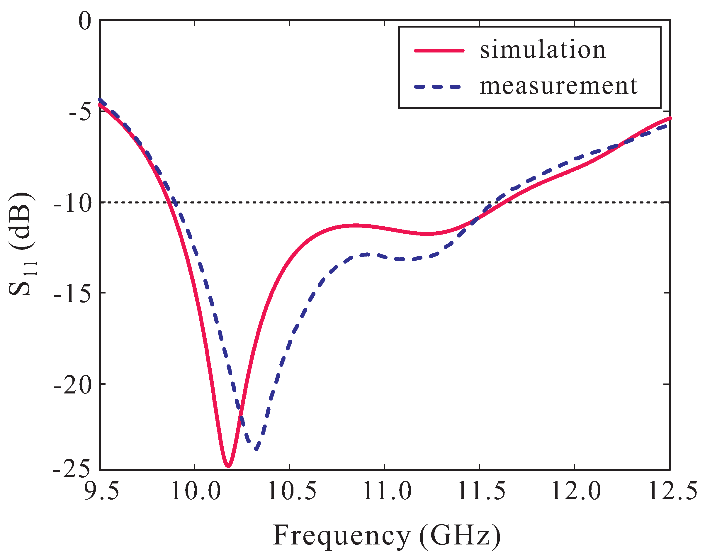
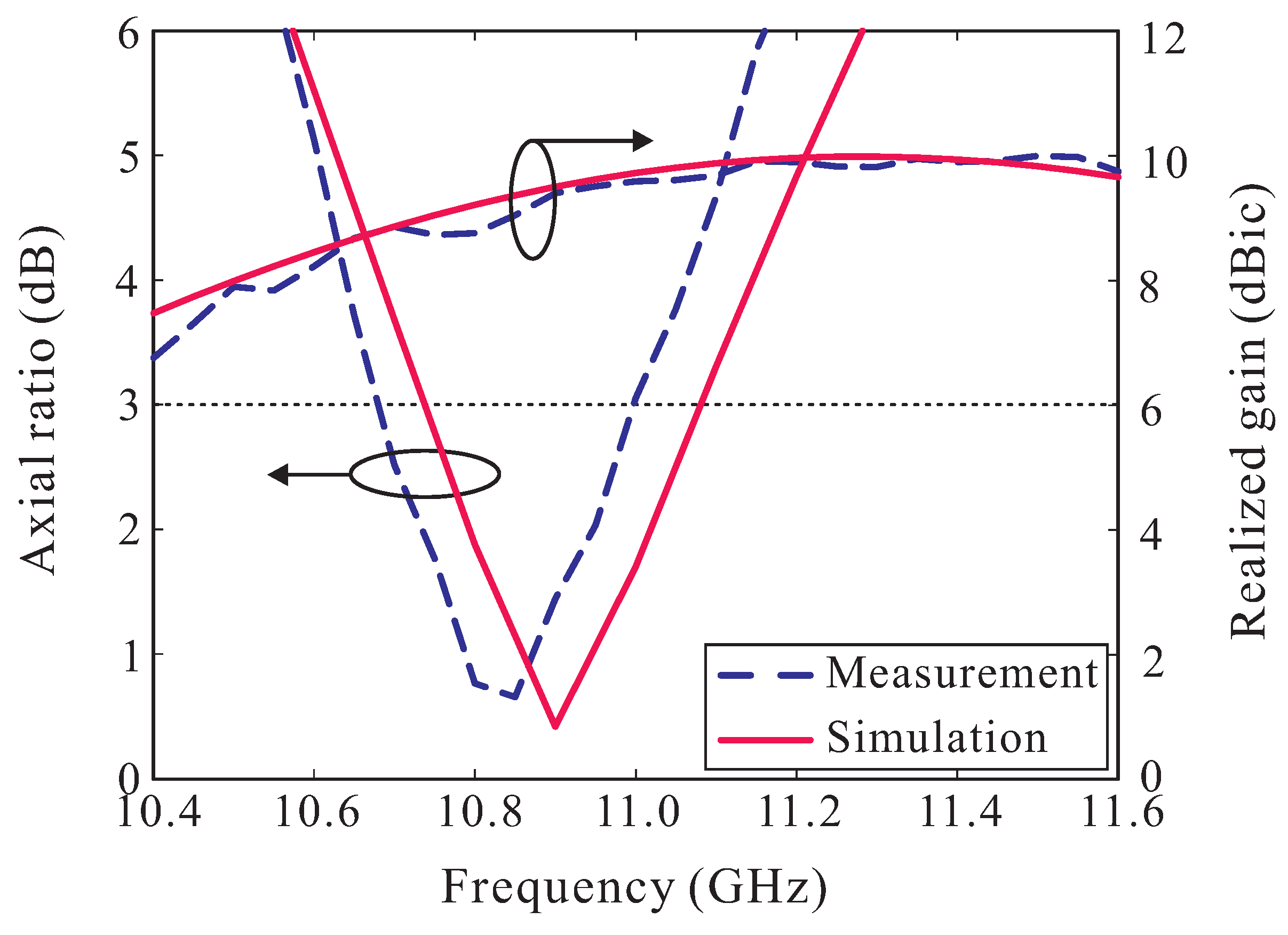
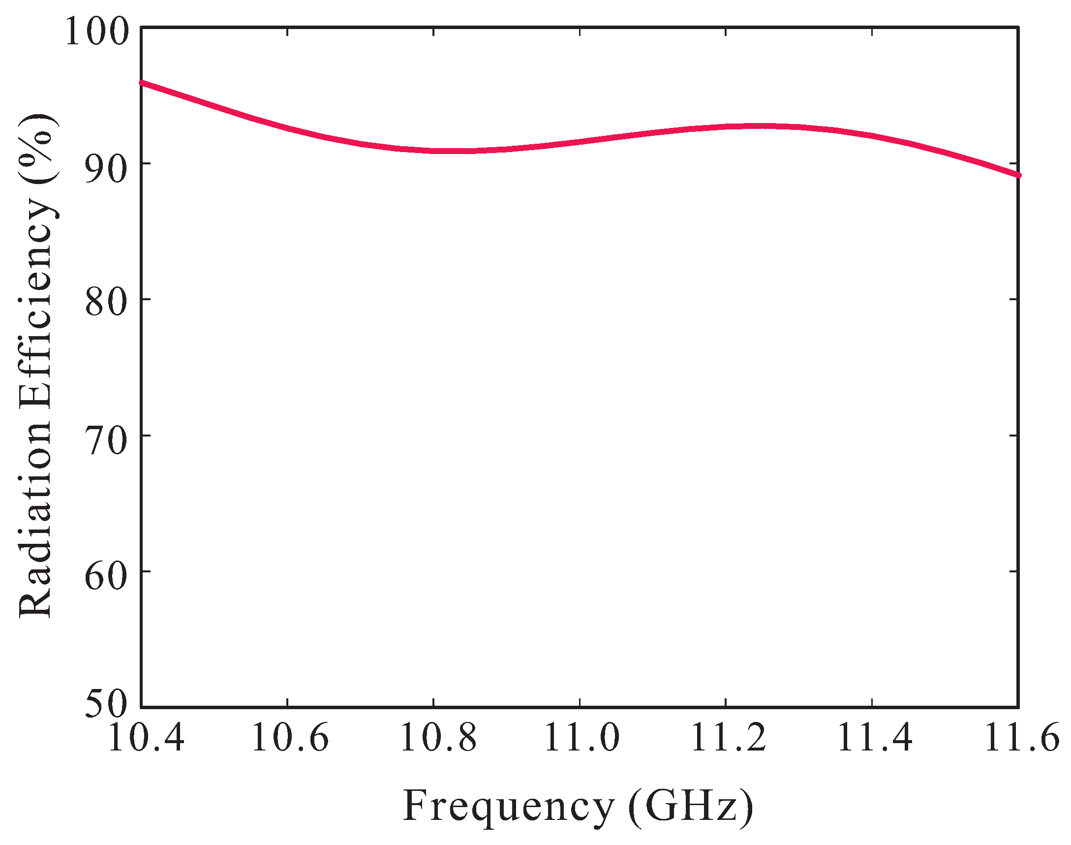
3. Experimental Results and Discussion

The proposed antenna was implemented, and the results are demonstrated. Photographs of the fabricated sample of the Spidron fractal aperture and an assembled model are shown in Figure 7. The antenna was fed directly by the WR-90 waveguide-to-coax adapter (model number: 16094-SF40). An Agilent 8510C RF network analyzer was employed to test the antenna reflection. Figure 8 shows the measured and simulated reflection coefficients. It was observed that the measured frequency bandwidth with −10 dB reflection was 9.89–11.58 GHz (15.74%). Good agreement was observed between the measurement and the simulation.
The AR value and realized RHCP gain of the implemented antenna in θ = 0 are shown in Figure 9. The measured 3 dB AR bandwidth is 10.68–11.00 GHz (2.95%), with a minimum AR value of 0.66 dB at 10.85 GHz. The measured 3 dB AR bandwidth is slightly shifted toward a lower frequency range compared with that in the simulated results. Within the operating AR frequency bandwidth, the measured RHCP gain varies from 8.73 to 9.59 dBic. The discrepancy between the measurement and the simulation can be attributed to fabrication tolerance and the misalignment between the Spidron fractal aperture and the waveguide aperture. Figure 10 presents the simulated radiation efficiency of the proposed antenna versus the frequency. The antenna efficiency within the measured 3 dB AR bandwidth is approximately 91%. Figure 11 plots the measured and simulated radiation patterns of the antenna on the x z - ( ϕ = 0 ) and y z -planes ( ϕ = 90 ) at 10.85 GHz. It can be seen that the antenna radiates RHCP waves and that the radiation patterns are directional, radiating toward the broadside direction. Furthermore, the measured RHCP gains are 21.5 dB higher than the left-handed circular polarization (LHCP) gain in the broadside direction on both planes. The simulated and measured ARs versus the observation angle of the proposed antenna at 10.85 GHz are illustrated in Figure 12. As observed, the measured 3 dB AR beamwidths are 46 and 43 on the xz- and yz-planes, respectively. Reasonable agreement between the simulation and the measured results is achieved.
Comparisons between the proposed waveguide-fed aperture antenna and similar counterparts reported in the literature are summarized in Table 2. Note that all of these antennas are fed by a WR-90 open-ended waveguide. As observed, all of the antennas in one study [4] are linearly polarized (LP) antennas, while the proposed antenna exhibits CP operation. Compared with another waveguide-fed CP antenna [11], which also includes a superstrate to achieve gain enhancement, the proposed antenna has a wider impedance bandwidth and a higher gain.

4. Conclusions

A high-gain rectangular waveguide-fed fractal aperture antenna with circular polarization operation was fabricated and tested, and the design and results are presented. A Spidron fractal aperture was employed to generate circular polarization and was fed directly by a WR-90 waveguide-to-coax adapter. To realize the high-gain characteristics, a superstrate was applied at an appropriate distance above the antenna. The experimental results proved that the proposed antenna has a −10 dB reflection bandwidth of 9.89–11.58 GHz (15.74%), a 3 dB AR bandwidth of 2.95% (10.68–11.00 GHz), and a maximum RHCP gain of 9.59 dBic. Unlike most antennas reported in earlier work [4], the proposed waveguide-fed Spidron fractal aperture antenna radiates CP waves. Therefore, it can be feasibly integrated into satellite communications and radar systems for X-band applications.

Author Contributions

The presented work was carried out in collaboration of all authors. S.T.-V. and T.N.T. performed the simulations. Y.Y., K.-Y.L., K.-Y.J., and K.C.H. participated to the conception, fabrication and experiment. S.T.-V. wrote the paper which was edited by all co-authors.

Funding

This work was supported by the National Research Foundation of Korea (NRF) grant funded by the Korean government (MSIP) (2018R1C1B6005024).

Conflicts of Interest

The authors declare no conflict of interest.

References

  1. Gupta, S.; Chakrabarty, A.; Das, B.N. Admittance of waveguide fed slot radiators. In Proceedings of the Digest on Antennas and Propagation Society International Symposium, San Jose, CA, USA, 26–30 June 1989; pp. 968–971. [Google Scholar]
  2. Werner, D.H.; Ganguly, S. An overview of fractal antenna engineering research. IEEE Antennas Propag. Mag. 2003, 45, 38–57. [Google Scholar] [CrossRef]
  3. Kubacki, R.; Czyzewski, M.; Laskowski, D. Minkowski island and crossbar fractal microstrip antennas for broadband applications. Appl. Sci. 2018, 8, 334. [Google Scholar] [CrossRef]
  4. Ghosh, B.; Sinha, S.N.; Kartikeyan, M.V. Radiation from rectangular waveguide-feed fractal apertures. IEEE Trans. Antennas Propag. 2010, 58, 2088–2093. [Google Scholar] [CrossRef]
  5. Fukusako, T. Broadband characterization of circularly polarized waveguide antennas using L-shaped probe. J. Electromagn. Eng. Sci. 2017, 17, 1–8. [Google Scholar] [CrossRef]
  6. Nelaturi, S.; Sarma, N.V.S.N. A compact microstrip patch antenna based on metamaterials for Wi-Fi and WiMAX applications. J. Electromagn. Eng. Sci. 2018, 18, 182–187. [Google Scholar] [CrossRef]
  7. Kweon, J.-H.; Park, M.-S.; Cho, J.; Jung, K.-Y. FDTD analysis of electromagnetic wave propagation in an inhomogeneous ionosphere under arbitrary-direction geomagnetic field. J. Electromagn. Eng. Sci. 2018, 18, 212–214. [Google Scholar] [CrossRef]
  8. Trinh-Van, S.; Yang, Y.; Lee, K.-Y.; Hwang, K.C. Broadband circularly polarized slot antenna loaded by a multiple-circular-sector patch. Sensors 2018, 18, 1576. [Google Scholar] [CrossRef] [PubMed]
  9. Hur, J.; Byun, G.; Choo, H. Design of small CRPA arrays with circular microstrip loops for electromagnetically coupled feed. J. Electromagn. Eng. Sci. 2018, 18, 129–135. [Google Scholar] [CrossRef]
  10. Asaadi, M.; Sebak, A. Gain and bandwidth enhancement of 2 × 2 square dense dielectric patch antenna array using a holey superstrate. IEEE Antennas Wirel. Propag. Lett. 2017, 16, 1808–1811. [Google Scholar] [CrossRef]
  11. Chandra, A.; Das, S. Superstrate and CSRR loaded circularly polarized dual-band open-ended wavguide antenna with improved radiation characteristics and polarization reconfiguration property. IEEE Trans. Antennas Propag. 2017, 65, 5559–5564. [Google Scholar] [CrossRef]
  12. Al-Tarifi, M.A.; Anagnostou, D.E.; Amert, A.K.; Whites, K.W. Bandwidth enhancement of the resonant cavity antenna by using two dielectric superstrates. IEEE Trans. Antennas Propag. 2013, 61, 1898–1908. [Google Scholar] [CrossRef]
  13. Hwang, K.C. Broadband circularly-polarised Spidron fractal slot antenna. Electron. Lett. 2009, 45, 3–4. [Google Scholar] [CrossRef]
  14. Nguyen Thi, T.; Hwang, K.C.; Kim, H.B. Dual-band circularly-polarised Spidron fractal microstrip patch antenna for Ku-band satellite communication applications. Electron. Lett. 2013, 49, 444–445. [Google Scholar] [CrossRef]
  15. Altaf, A.; Yang, Y.; Lee, K.-Y.; Hwang, K.C. Circularly polarized Spidron fractal dielectric resonator antenna. IEEE Antennas Wirel. Propag. Lett. 2015, 14, 1806–1809. [Google Scholar] [CrossRef]
  16. Trentini, G.V. Partially reflecting sheet arrays. IRE Trans. Antennas Propag. 1956, 4, 666–671. [Google Scholar] [CrossRef]
  17. Chen, Q.; Chen, X.; Xu, K. 3-D printed Fabry-Perot resonator antenna with paraboloid-shape superstrate for wide gain bandwidth. Appl. Sci. 2017, 7, 1134. [Google Scholar] [CrossRef]
  18. Hashmi, R.M.; Zeb, B.A.; Esselle, K.P. Wideband high-gain EBG resonator antennas with small footprints and all-dielectric superstructures. IEEE Trans. Antennas Propag. 2014, 62, 2970–2977. [Google Scholar] [CrossRef]
Figure 1. Topology of the proposed antenna: (a) exploded 3-D view; (b) side view; (c) Spidron fractal aperture.
Applsci 09 00691 g001
Figure 2. (a) Design process; simulated results of (b) reflection coefficients and (c) simulated axial ratios (ARs).
Applsci 09 00691 g002
Figure 3. Simulated magnetic current distributions of the Spidron fractal aperture at 11.1 GHz: (a) t = 0; (b) t = T/4.
Applsci 09 00691 g003
Figure 4. Multiple reflections between the superstrate and the ground plane.
Applsci 09 00691 g004
Figure 5. (a) Simulation model of the unit cell; (b) reflection phase of the superstrate.
Applsci 09 00691 g005
Figure 6. Effect of the superstrate on antenna performance: (a) reflection coefficients; (b) axial ratios (ARs); (c) RHCP gains (RHCP: right-handed circular polarization).
Applsci 09 00691 g006
Figure 7. (a) Photograph of the fabricated sample of the Spidron fractal aperture; (b) assembled antenna.
Applsci 09 00691 g007
Figure 8. Measured and simulated reflection coefficients of the proposed antenna.
Applsci 09 00691 g008
Figure 9. Measured and simulated axial ratios (ARs) and RHCP gains versus the frequency of the proposed antenna.
Applsci 09 00691 g009
Figure 10. Simulated radiation efficiency of the proposed antenna versus the frequency.
Applsci 09 00691 g010
Figure 11. Measured and simulated radiation patterns at 10.85 GHz: (a) x z -plane; (b) y z -plane. LHCP: left-handed circular polarization.
Applsci 09 00691 g011
Figure 12. Measured and simulated axial ratios (ARs) of the proposed antenna versus the observation angle at 10.85 GHz.
Applsci 09 00691 g012
Table 1. Optimized dimensional parameters of the proposed antenna.
ParameterValueParameterValue
h s u b 0.51 mm d x 6.79 mm
h s u p 0.64 mm d y 4.226 mm
S15.5 mm β 1 34.94
h7.0 mm β 2 32.96
Table 2. Comparison between the proposed waveguide-fed aperture antenna and those in previous works.
Related PapersType of Aperture−10 dB Reflection BandwidthPolarization State/3 dB AR BandwidthPeak Gain
[4]Hilbert curve aperture5.7%LP5 dBi
Plus-shaped fractal aperture12.5%LP5 dBi
[11]Double complementary split-ring resonator1st band (3.5%)CP/3.03%5.92 dBi
2nd band (7.7%)CP/6.44%8.68 dBi
This workSpidron fractal aperture15.74%CP/2.95%9.59 dBi
AR: axial ratio; LP: linearly polarized; CP: circularly polarized.

