3.1.1. Test Specimens, Methods and Design of Experiments
Table 1 shows that much research is carried out in material development. However, the listed studies investigate only isolated process-specific influencing factors on resistivity. In addition, the studies do not derive design principles or rules to support the design of additively manufactured conductive structures or heat radiant surfaces. Therefore, in this contribution, two different specimens were developed to determine process- and material-specific variations of resistivity regarding two of the main applications: electrical conductors and heat radiating surfaces (see
Section 2.1). The first specimen for the characterization of the resistance was inspired by the form of an electrical conductor (see
Figure 1), whereas the second specimen was much broader and formed as a flat rectangle (see
Figure 2) to reproduce a heat radiating structure. As the raster angle orientation regarding the adjustability of resistivity is hardly considered in the studies mentioned above, it was focused in in this contribution. Solely, Watschke et al. (2017) [
1] investigated specifically the influence of different infill patterns on resistivity and found that it provides a vast potential for adjusting the resulting resistance of additively manufactured structures. Indeed, they only analyzed the carbon black filled material Proto-pasta Conductive PLA [
25]. Consequently, a transferability of the results to other materials with different fillers is not examined.
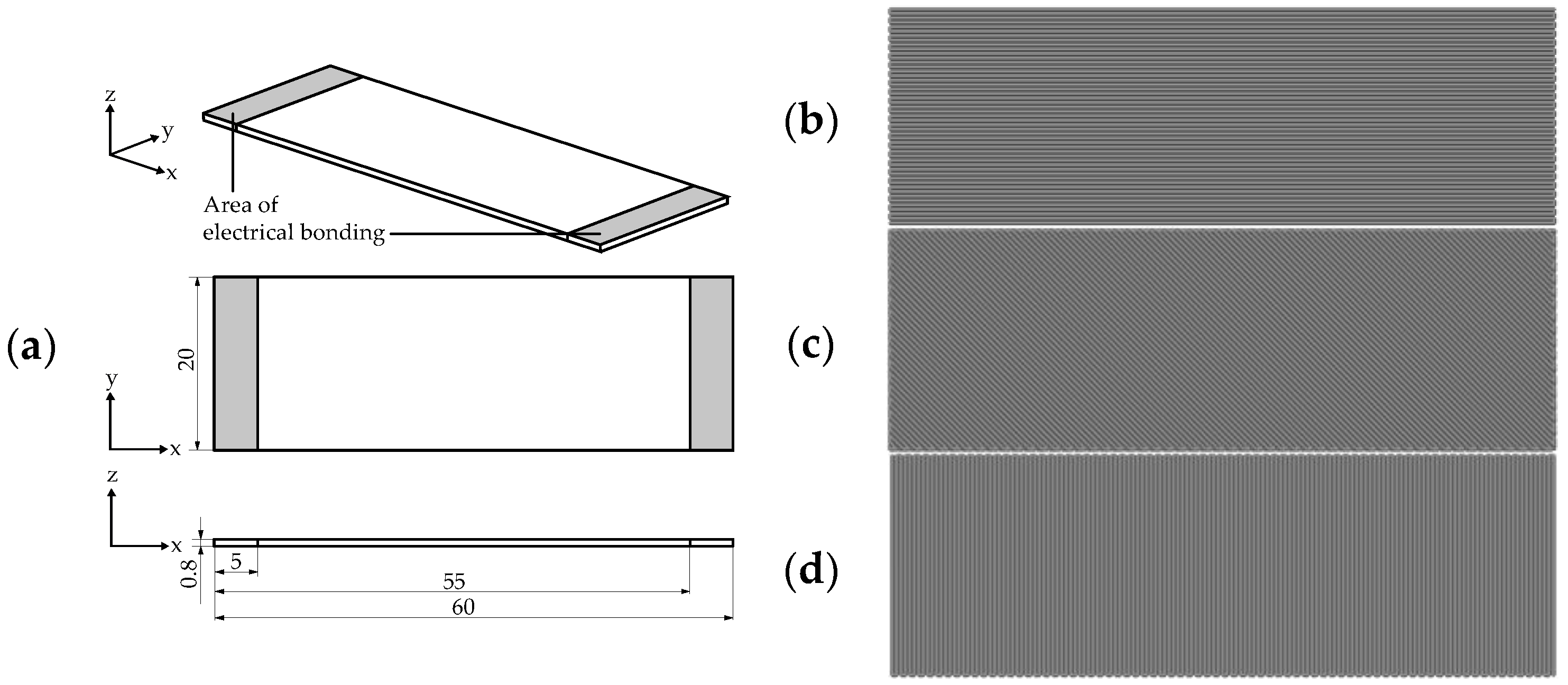
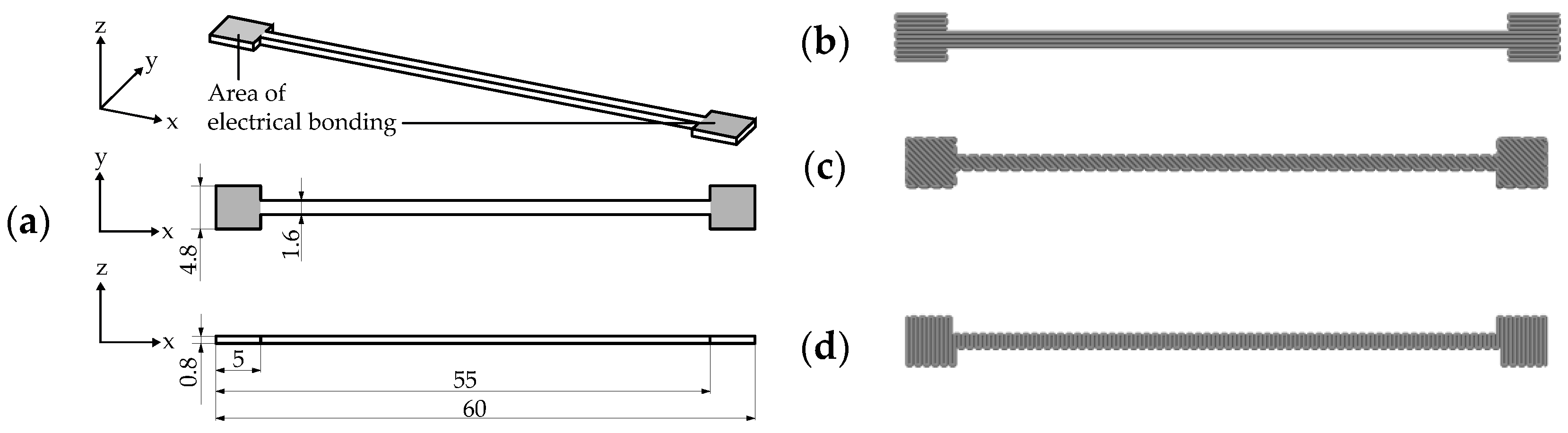
Figure 1a shows the specimen and its dimensions for the characterization of resistivity of different process parameter sets. The resistance was measured between the areas of electrical bonding that are highlighted in grey. Since, according to Hampel et al. (2017) [
4] and Watschke et al. (2017) [
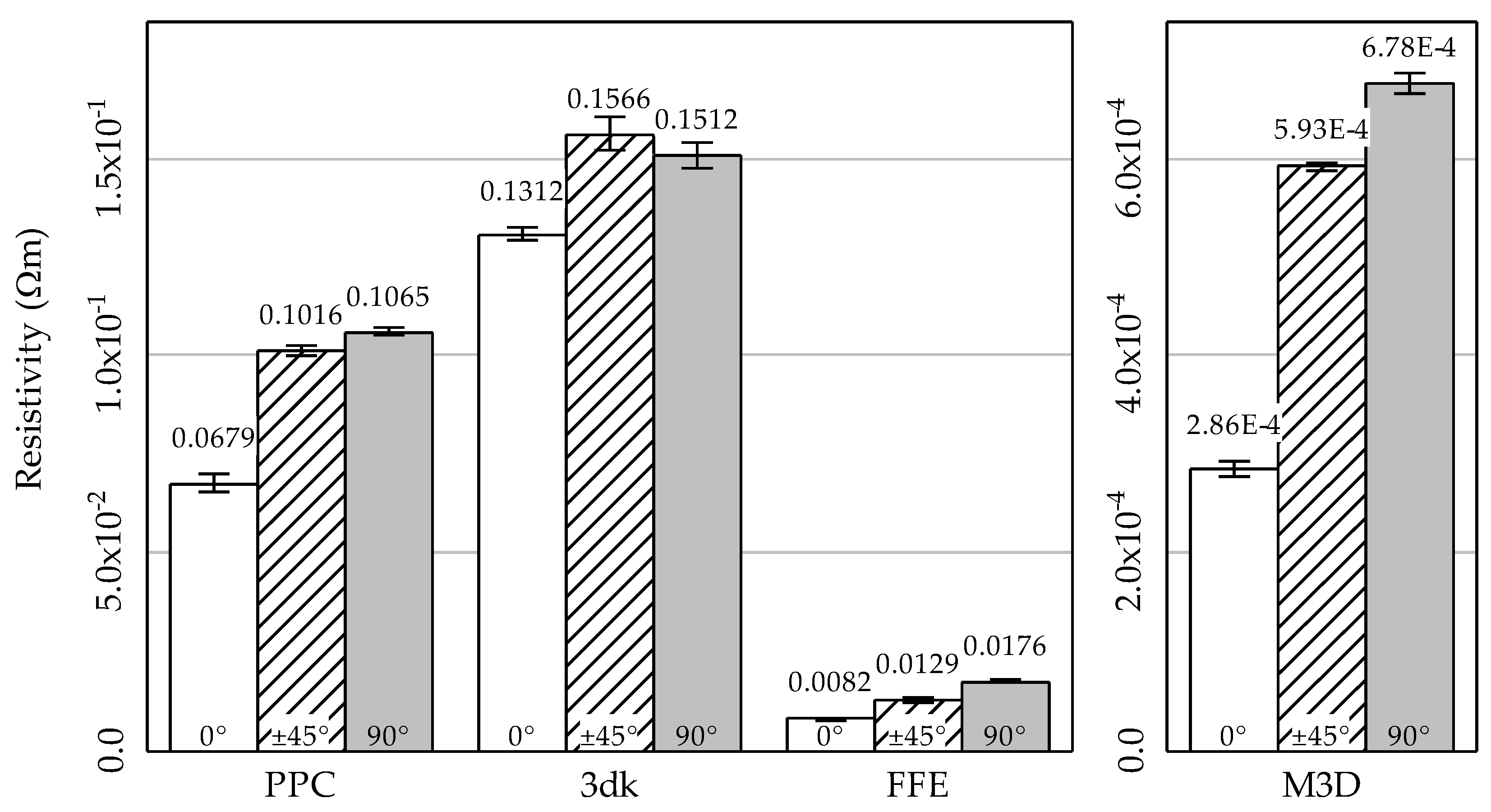
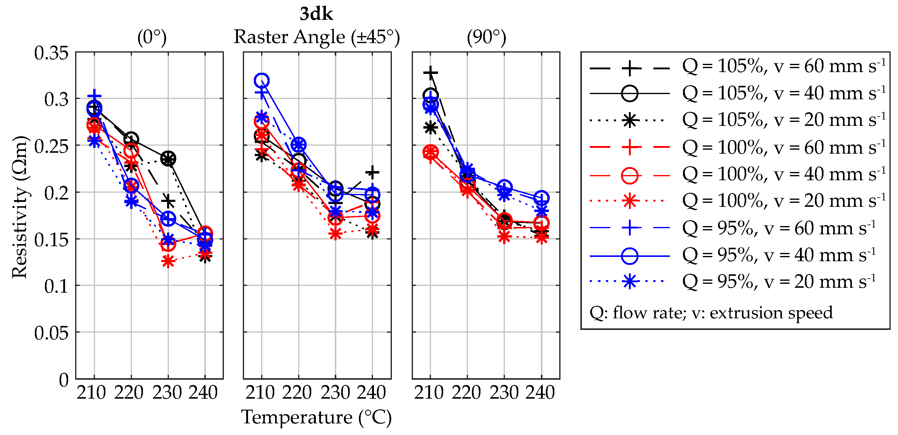
1], the infill pattern has a strong influence on the electrical resistance due to the varying number of strand boundaries, the raster angle orientation was explicitly taken into account in the experimental investigations. To determine solely the influence of the raster angle orientation, the perimeter shells were disabled in the slicing process. The resulting trajectories of the used raster angle orientations of 0°, ±45° and 90° are represented in
Figure 1b–d. The specimens were directly processed on object slides (see
Section 3.1.2).
Figure 2 shows both the dimensions of the specimen for the experimental investigation of the heat radiation capacity and the trajectories used for the additive manufacturing process. The dimensions are similar to the specimen shown in
Figure 1. The height (0.8 mm) as well as the overall length (60 mm) and length between the electrical bonding (50 mm) are identical. Since the homogeneity of both the heat radiation and the heating of the specimen were analyzed, the width of the specimen was chosen as 20 mm. Thus, the manufacturability on an object slide was still possible to ensure equal boundary conditions for the manufacturing. Because of the increased width, the effect of the AM-machine’s acceleration at the boundary was less for the resistivity of the overall structure.
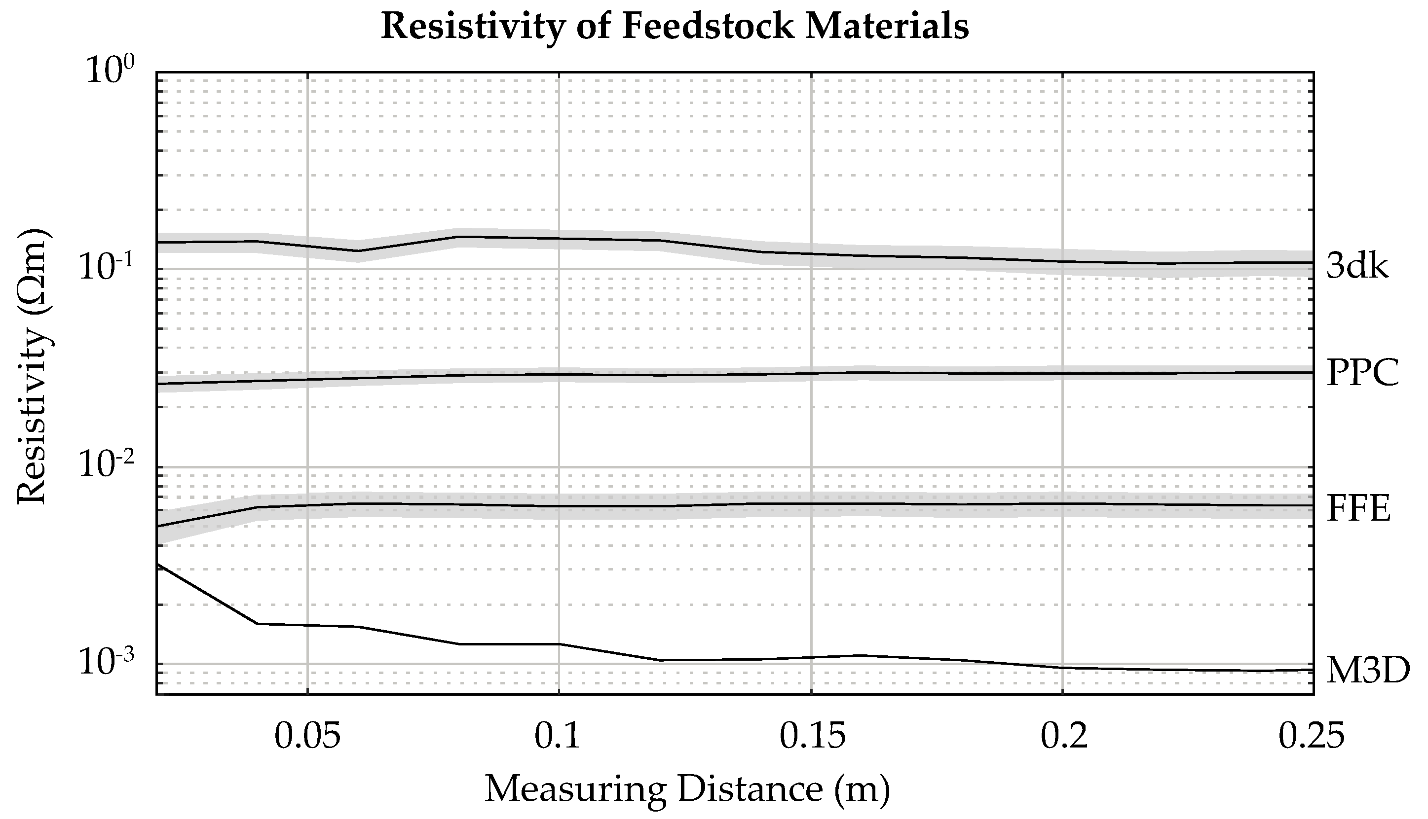
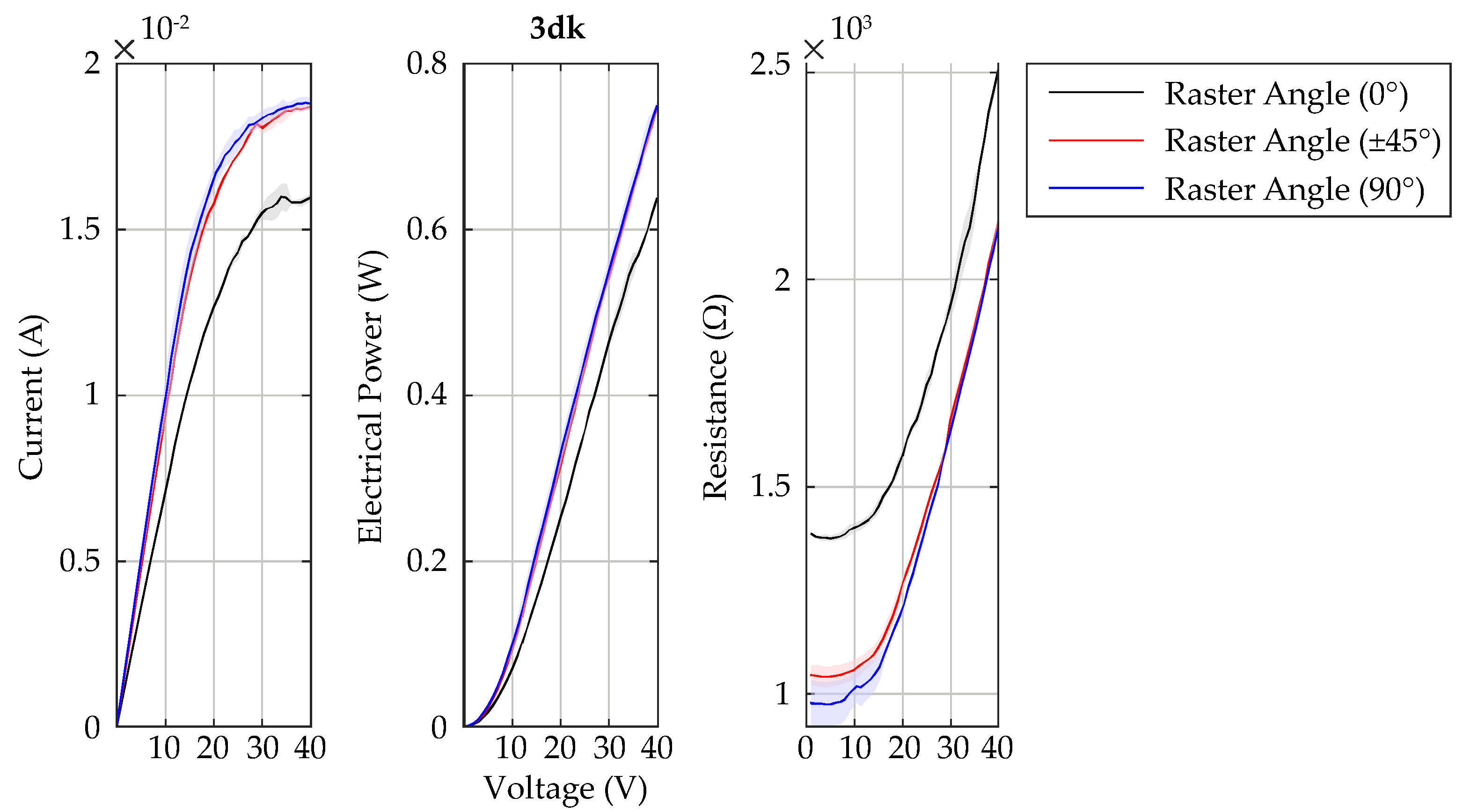
As many materials with different fillers are available for MEX, the following four different material composites were exemplarily chosen for the design of experiments: Proto-pasta Conductive PLA (PPC) [
25], 3dkonductive PLA (3dk) [
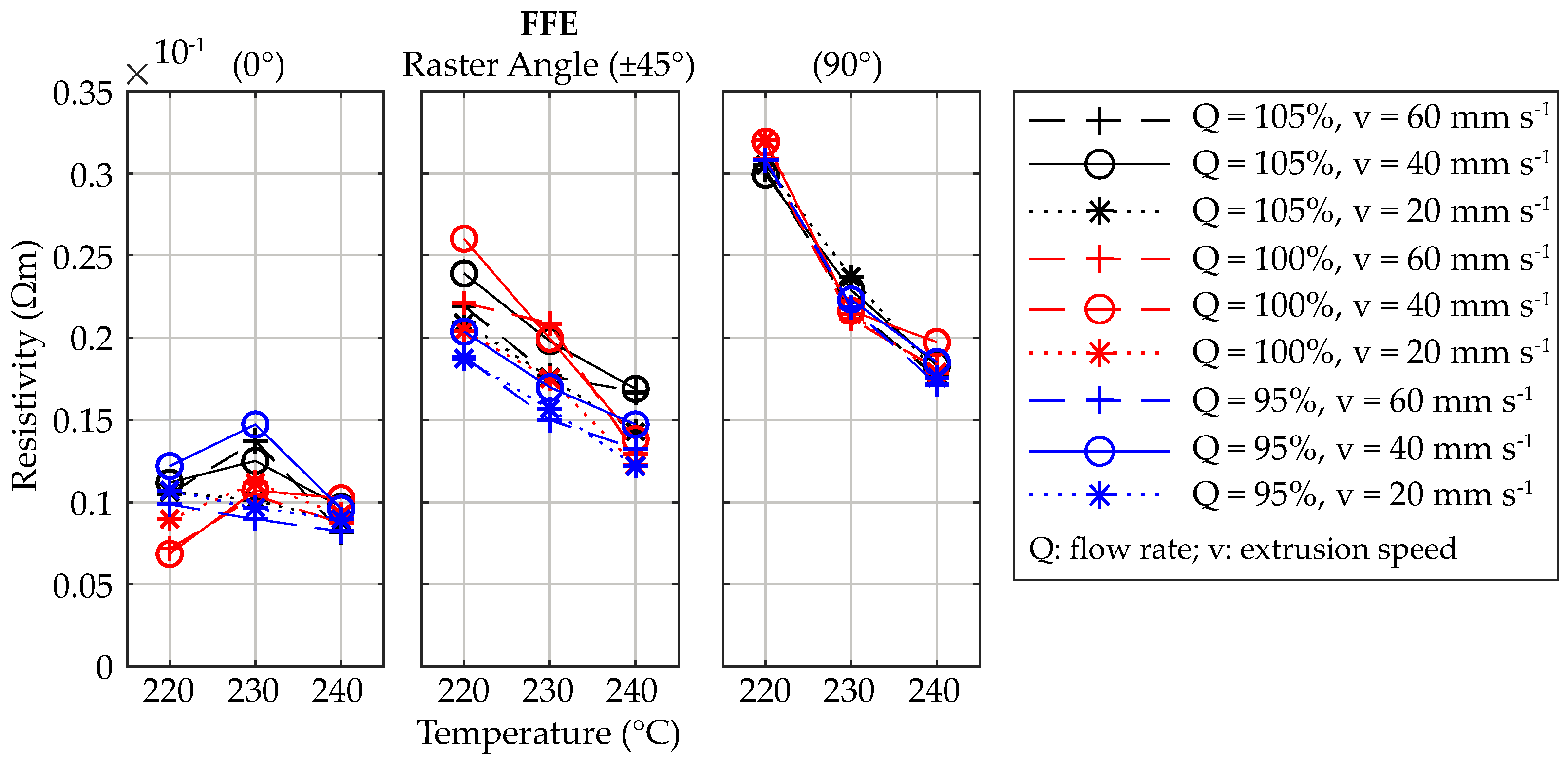
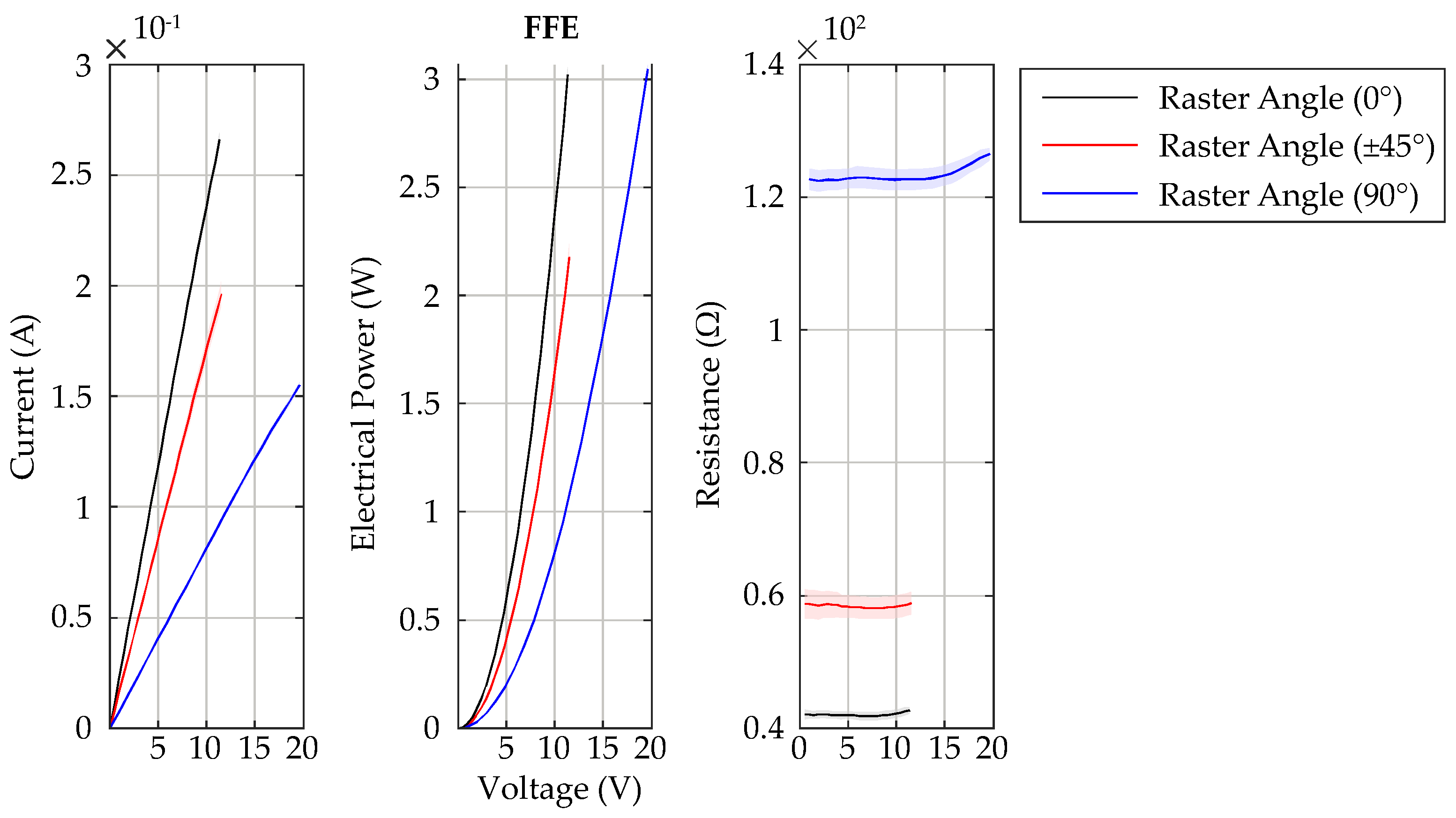
26], Functionalize F-Electric™ PLA (FFE) [
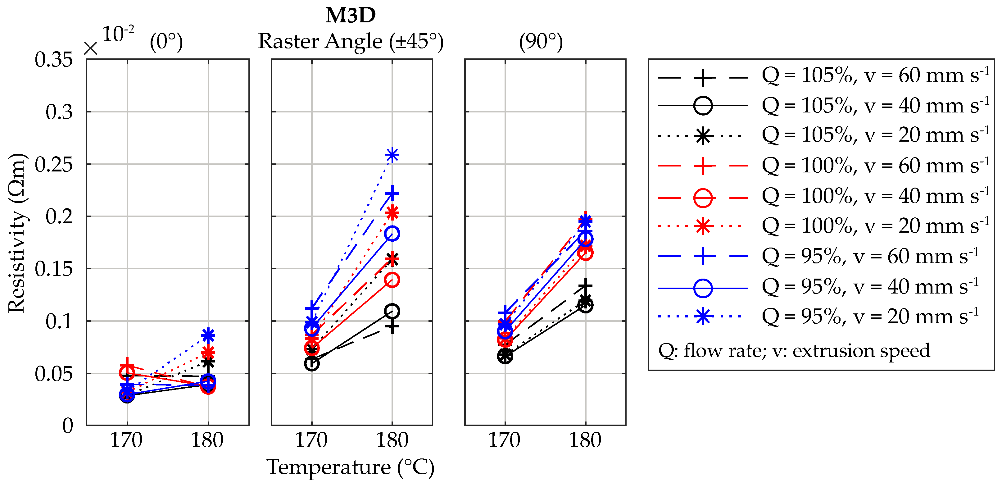
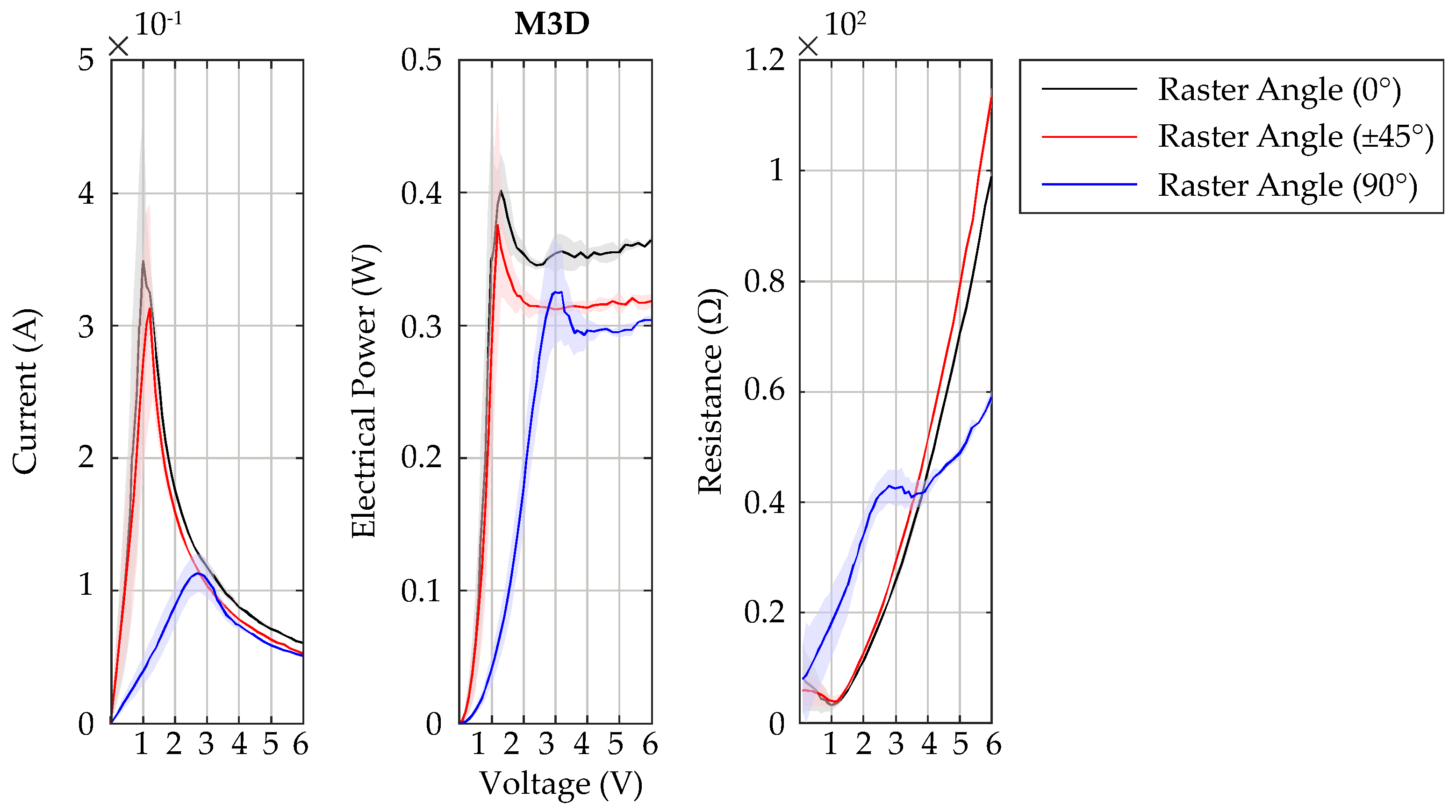
27], and MULTI3D Electrifi Conductive Filament (M3D) [
28] (see
Table 2). Thus, three different fillers were investigated to determine their process parameter specific influence on resistivity. Both PPC and 3dk use as filler CB and, therefore, have a significant higher resistance than the CNT (FFE) and copper filled material (M3D). Thus, by utilizing these materials, various design opportunities were possible, e.g., electrical conductors, heat radiation surfaces, or flexible sensor (cf.
Table 1). Besides information about feedstock material’s resistivity,
Table 2 also shows the processing conditions of the individual materials.
Table 3 presents the design of experiments for determining material- and process-specific dependencies of resistivity. The variation parameters were selected based on the literature review and the ranges of the individual process parameters in accordance with the processing conditions shown in
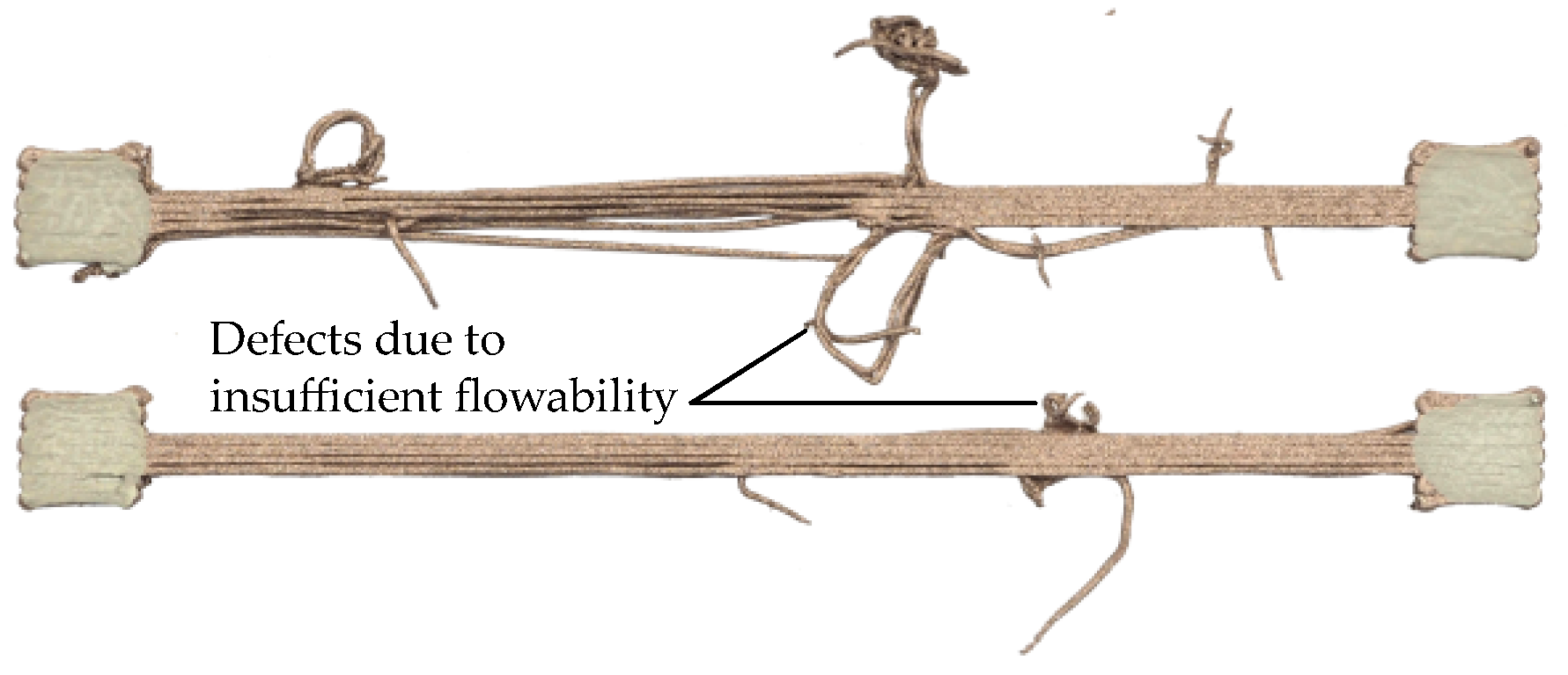
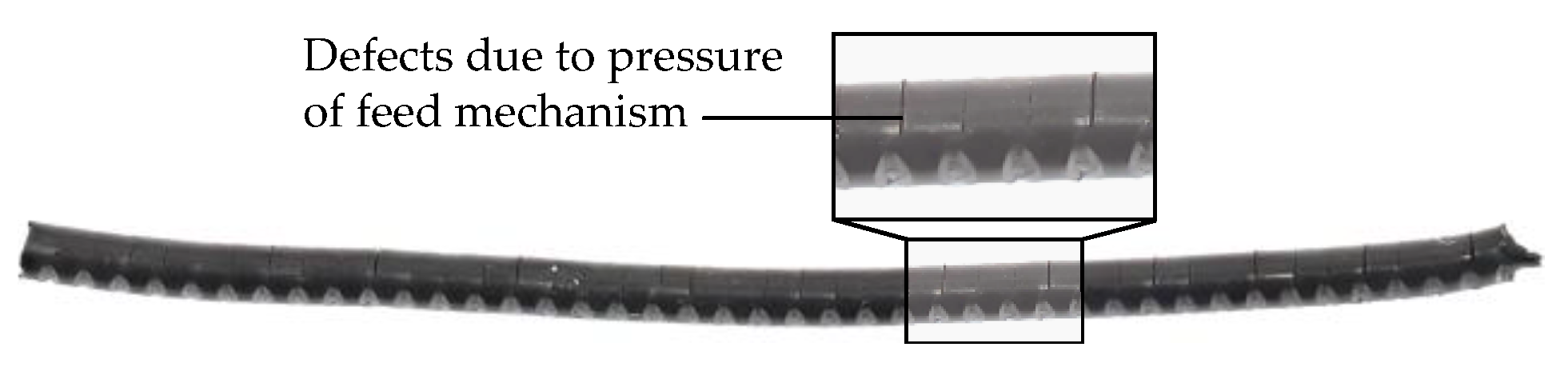
Table 2. Even though other parameters such as line width or overlap also influence the compaction between layers and thus resistivity, these parameters were not considered in this contribution due to the increased scope of the experimental investigations. The maximal extrusion temperature was chosen as 10 °C above the recommended temperature. It has to be noted that the materials FFE and M3D are not processable below an extrusion temperature of 220 °C or 170 °C caused by a low flowability (see
Figure 3). Therefore, the minimal extrusion temperature was set to 220 °C for FFE and 170 °C for M3D. Besides the extrusion temperature, high speed may also result in defects and, thus, in a damaged specimen, thus the maximum speed was set to 60 mm/s. It is worth noting that the range of process parameters can be increased by changes in manufacturing conditions, for example, varying build platform temperature or using additional types of adhesives.
A full fractional parameter variation was chosen for each material. Thus, 351 batches each with three specimens were manufactured. Consequently, in total, 1053 specimens were additively manufactured in the selected design of experiments. The conditions of manufacturing are described in detail in
Section 3.1.2. The design of experiments was limited to the determination of resistivity (cf. specimen shown in
Figure 1). The measurement of the heat resistivity was solely conducted with selected process parameter sets that exhibit low electrical resistance. These specimens were defined based on the experimental investigations regarding resistivity.
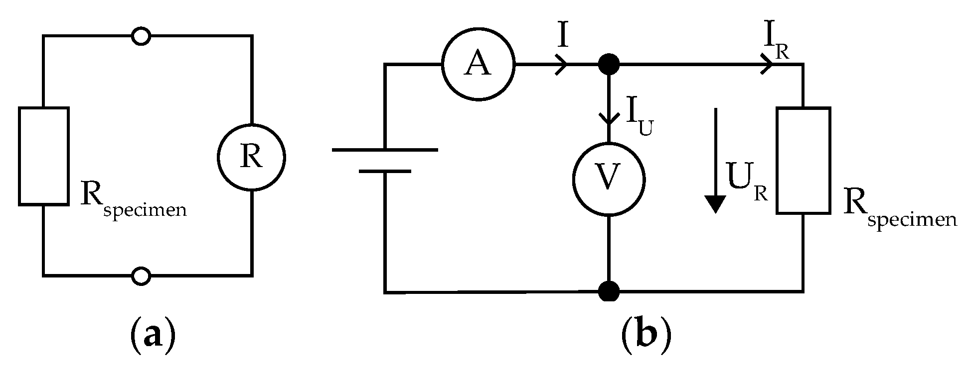
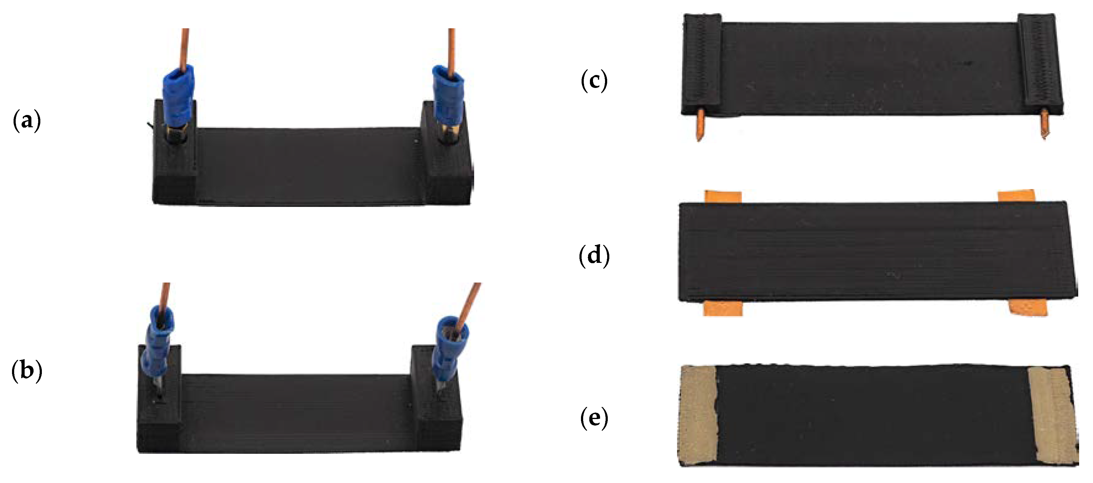
The different test set-ups represented in
Figure 4 were used to determine the electrical resistance of the two presented test specimens for electrical resistivity and heat radiation capacity. The testing was carried out at ambient temperature of 23 ± 1 °C and a relative humidity of 45–50%. For the measurement of the resistance of the specimens shown in
Figure 1, the test set-up shown in
Figure 4a and a VOLTCRAFT MT-52 (Conrad Electronic AG, Wollerau, Switzerland) were used.
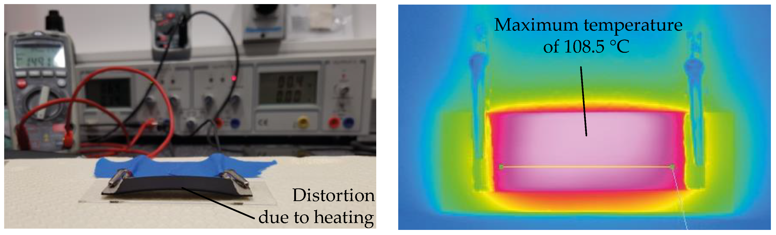
The experimental set-up for the determination of the current–voltage characteristics is shown in
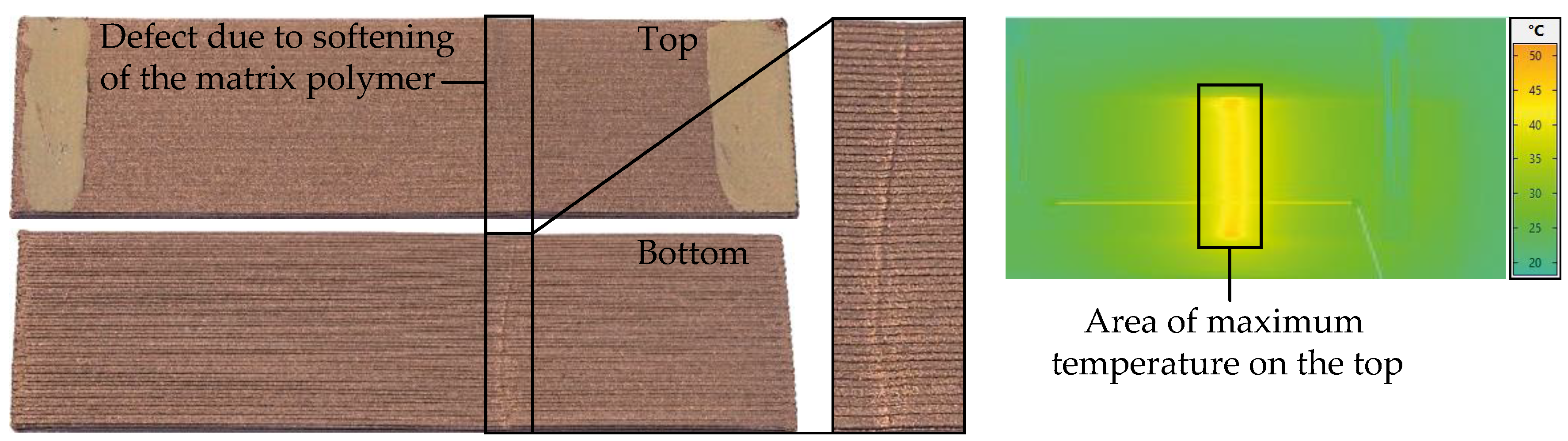
Figure 4b. The maximum applied voltage depends on the resulting electrical capacity that damages the specimens when exceeding the heat deflection temperature of the matrix material due to resistive heating. The material- and process-specific maximum voltage was determined in preliminary investigations for each specimen. A VOLTCRAFT VLP 2403pro was used as a direct current (DC) power supply. Further, a VOLTCRAFT MT-52 (Conrad Electronic AG, Wollerau, Switzerland) was used for measuring the voltage U and the current I was measured by a VOLTCRAFT VC-110 (Conrad Electronic AG, Wollerau, Switzerland). The resulting resistance of the specimen was determined according to Equations (1) and (2), where R
impedance is 10 MΩ:
The calculation of the resistivity was carried out using Equation (3), where R is the measured electrical resistance, A the cross-section of the test specimen, and L the distance between the areas of electrical bonding:
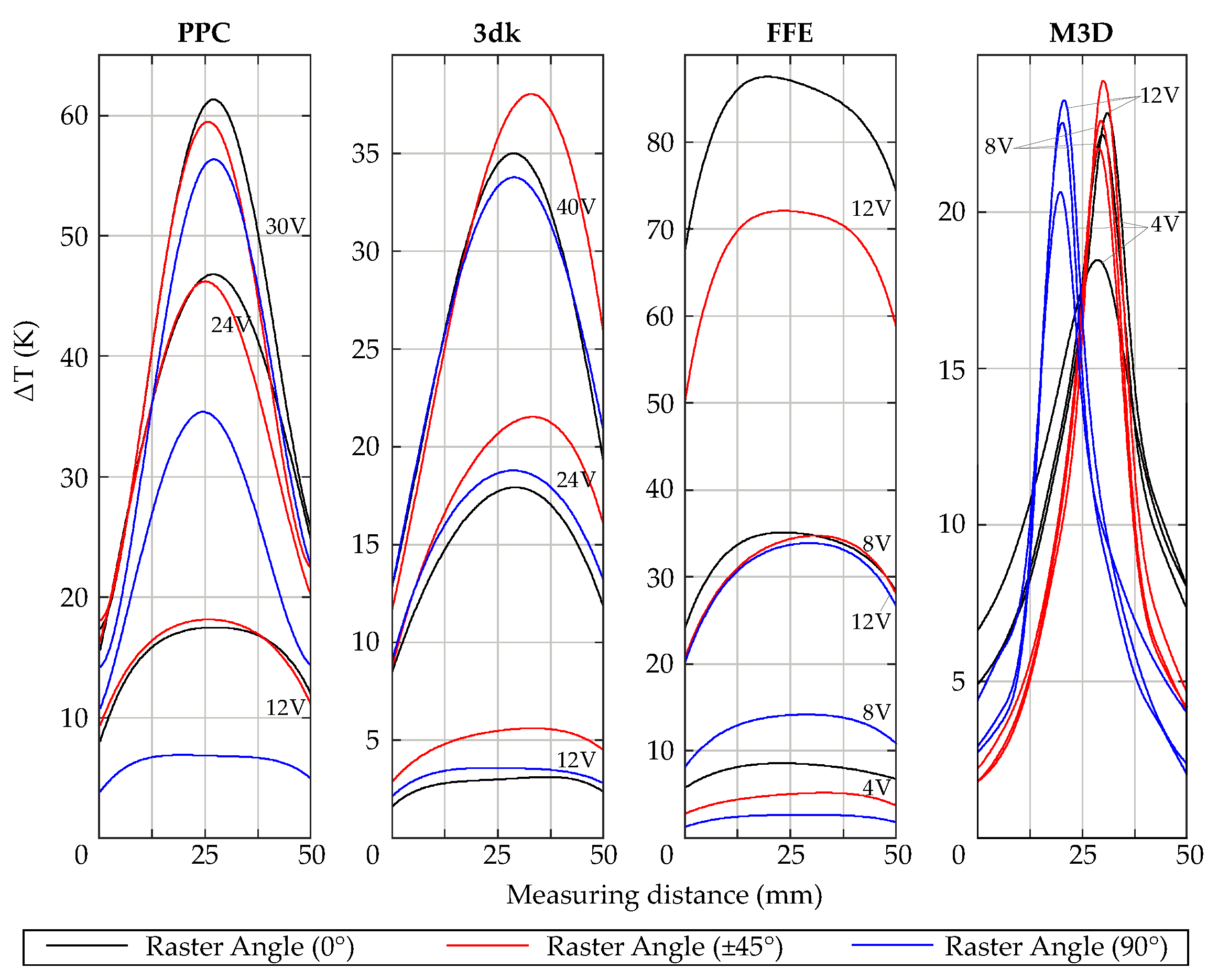
Besides the resistive current–voltage characteristics, the surface temperature generated by resistive heating was measured by a VarioCAM® HD head 800 thermographic camera (InfraTec GmbH, Dresden, Germany) with the software IRBIS® 3. To determine the heat distribution, the surface temperature was measured at different voltages individually for each material and process parameter set.
3.1.2. Machine and Manufacturing of Test Specimens
Material extrusion was chosen for the manufacturing of the test specimens, since multi-material MEX allows a combination of multiple materials for incorporation electrically conductive structures. MEX uses thermoplastic polymers as feedstock materials that are directed into an extruder unit where the material is melted. The plasticized material is applied to a build platform or previous layer according to the individual cross section of the generated part. Due to thermal fusion, the applied layer bonds with the surrounding already solidified material. In this way, the part is generated layer by layer [
8]. The process of multi-material MEX was shown and described in more detail, for example, by Watschke et al. (2018) [
29]. For manufacturing of the specimens, the pro-consumer machine X400 by German RepRap GmbH (Feldkirchen, Germany) with a dual extruder system was used. The printer comes with a heated build platform and a direct extruder with a nozzle diameter of 0.4 mm. For the preparation of the build job, the slicing software Simplify3D (version 4.0) was used.
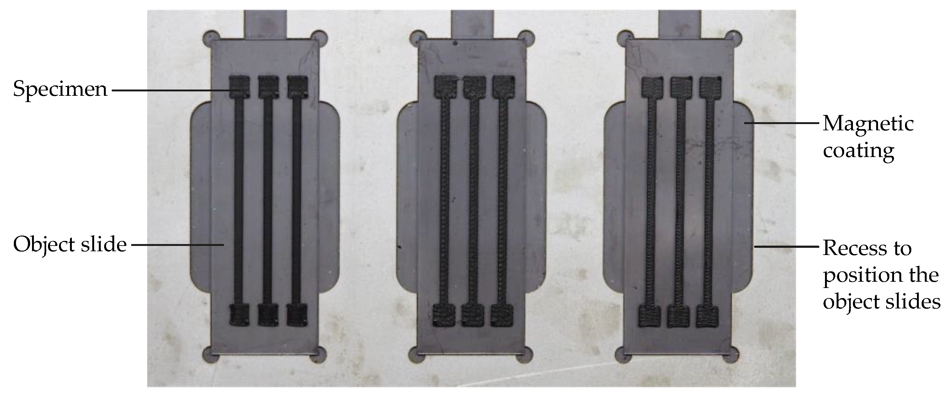
Table 2 gives an overview of the utilized process parameter sets. In addition, the line width was set to 0.4 mm and no perimeter shells were used. The material was directly processed on object slides that were positioned in recesses in a sheet metal (see
Figure 5). In the sheet metal, three object slides can be positioned. On each object slide, three test specimens were printed with the same set of process parameters. In one build job, three batches were manufactured one specimen after another to ensure repeatable process conditions. In addition, solely the extrusion speed varied in one build job, whereas extrusion temperature, flow rate, and raster angle orientation were equal. All specimens were manufactured by using the identical calibration set-up and the same environmental conditions (ambient temperature of 23 ± 1 °C and a relative humidity of 45–50%).
Due to this experimental set-up, the specimens did not have to be removed from the build table after the manufacturing process, thus damage due to the removal was avoided. Further, the electrical bonding and the measurement of the electric resistance was conducted without detaching the specimens from the object slides. Thus, the repeatability of both the manufacturing process and the characterization of the specimen’s resistance was improved. The specimens for analyzing heat radiation capacity were also directly processed on object slides.
Before starting the manufacturing process, the materials were dried: the materials based on PLA at 45 °C and M3D at 30 °C, for 4 h each. To ensure equal environmental conditions during the printing process, the materials were stored in a box during the manufacturing process that regulates relative humidity at about 20%. Before testing, all specimens were stored at an ambient temperature of 23 ± 1 °C and a relative humidity of 45–50% for at least one week in the laboratory.


