Abstract
We present a novel method to accurately measure the vertex position of a large aspheric mirror with a phasing measuring interferometer, a laser tracker, and a micro alignment telescope. The method consists of rotating the mirror by 180° about its mechanical axis and measuring the change in displacement. Use of a micro alignment telescope eliminates the need to adjust the mirror during the measurement, eases the alignment of the testing system, and improves the vertex position measurement accuracy. Using this method, we measured the vertex position of an aspheric mirror 1 m in diameter and 2 m in radius of curvature. The vertex position measurement uncertainty is 88 μm.
1. Introduction
Accurate measurement of the vertex position of a large aspheric mirror is often critical to the performance of the optical system in which the mirror is used. Take the monolithic primary tertiary mirror as an example, the Large Synoptic Survey Telescope (LSST) uses a unique opto-mechanical design that places the primary and tertiary mirrors on a single glass substrate, the alignment of primary and tertiary mirrors is controlled at the time of manufacture; the tolerance in lateral displacement of the two vertices is 1 mm [1,2,3]. Another example is the space telescope, which has very limited alignment space, and the vertex eccentricity of the primary mirror is often required to within less than a millimeter from nominal.
The displacement of the vertex causes shear of the spherical aberration terms, resulting in coma in surface form [4]. However, it is difficult to determine vertex position from measurement of surface form because of low sensitivity. Take a parabolic mirror with 1.3 m in diameter and 3.5 m in radius of curvature (RoC) as an example, an error of 1 mm in the measurement of the vertex position only induces 2 μm (Peak-to-Valley, PV) surface form error.
A variety of methods exists to measure the vertex position of an aspheric mirror. The mechanical method uses a coordinate measuring system, such as a coordinate measuring machine (CMM) or laser tracker to measure the surface coordinates and calculate the best-fit vertex position; the mechanical method is less efficient and often not applicable for large polished mirrors. The second method uses a phase measuring interferometer (PMI) and a null corrector. When the test optics are aligned to the mirror surface, the null corrector accurately defines the optical axis. The position and orientation of the null corrector and the position of the mirror’s mechanical axis can be measured by a portable coordinate measuring system (CMS, such as a laser tracker), and the vertex position can be subsequently calculated. A shortcoming of this method is that a small error in the measurement of the null corrector’s orientation results in a large error in the calculation of the vertex position due to Abbe error [5]. The third method consists of rotating the mirror by 180 degrees about its mechanical axis and measuring the change in coma. Two drawbacks associated with this method are as follows. First, the method depends on a high accuracy rotating table and precise alignment of the test piece so that the PMI can measure the mirror surface both at 0 degrees and 180 degrees without adjustment. Second, the method relies on stable positioning of the test optics, which is difficult in large-scale dimensional measurement.
The need to carefully match the vertex position of a large aspheric mirror presents an interesting challenge for the optics shop. Accurately measuring the vertex position using conventional methods is extremely difficult. In the following sections, we present a technique to use a PMI, a laser tracker and a micro alignment telescope (MAT) to perform vertex position measurement on an aspheric mirror. The method eliminates the aforementioned drawbacks, and accurate measurement of the vertex position is achieved.
2. Methods
The method is actually an improvement of the rotating method. Instead of measuring the change in coma with the PMI, the method only uses the PMI for alignment and directly measures the displacement with the MAT.
In this method, a PMI and a null corrector which generates an aspheric wavefront are used to build a virtual axis. The virtual axis will always pass through the mirror’s vertex when the test optics are well aligned to the mirror surface at each rotating angle.
A laser tracker is used to align a visible target for MAT to the mirror’s mechanical center (often defined by the outer diameter). A laser tracker is a portable CMS that utilizes a distance measuring interferometer (DMI) and two rotary encoders to track and measure the location of a sphere-mounted retro-reflector (SMR).
The MAT allows the user to set reference lines of sight for applications such as the alignment and measurement of bearings and bores. By use of two built in optical micrometers, two dimensional displacements can be measured with high accuracy from a reference line of sight. The MAT is moved together with the test optics so that it can maintain relative position and orientation with the virtual axis. If the vertex is not at mirror’s mechanical center, the MAT could observe target displacement after rotating the mirror and re-aligned to the test optics. Thus, the vertex position can be determined with two dimensional displacements from the MAT.
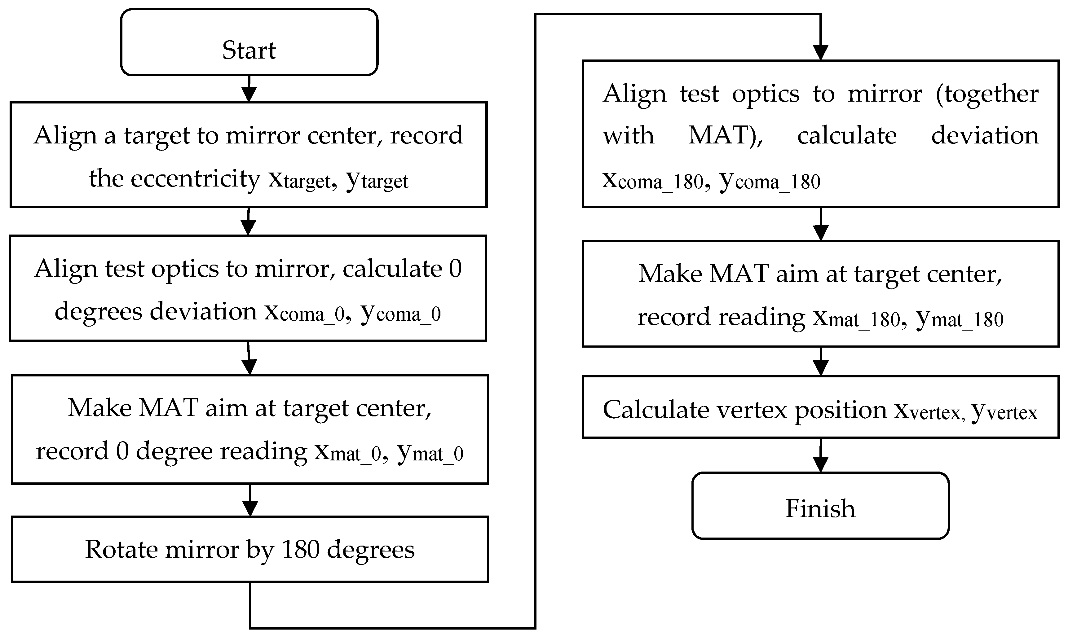
The measurement sequence is as follows (see Figure 1):

Figure 1.
Vertex position measurement process.
- Use a laser tracker to measure the mechanical center of the mirror and align a target (for MAT) to mirror’s mechanical center, record the eccentricity xtarget, ytarget.
- Deploy the PMI, null corrector such that the optical axis of test optics coincides as closely as possible with mirror’s optical axis, read the coma terms cx_0, cy_0, and calculate alignment deviation xcoma_0, ycoma_0 with mirror’s parameter.
- Deploy the MAT, place it along with PMI and test optics (on the same 5-axis table), and aim at the target center, record the reading of two micrometers: xmat_0, ymat_0.
- Rotate the mirror by 180 degrees, adjust 5-axis table to re-align optical path and calculate alignment deviation xcoma_180, ycoma_180 with coma terms.
- Adjust the MAT’s micrometers, aim at the target center, and record the reading of micrometers xmat_180, ymat_180.
- The displacements between the vertex position and mirror’s mechanical center can be calculated as:
3. Experiment and Results
The preliminary experiment is carried out on a concave aspheric mirror 1 m in diameter and 2.1 m in RoC. The mirror is supported by a whiffletree structure on a steel plate and can be rotated manually. The form error of the mirror is 0.1λ (rms, with piston, tilt, power and coma terms removed, λ = 632.8 nm).
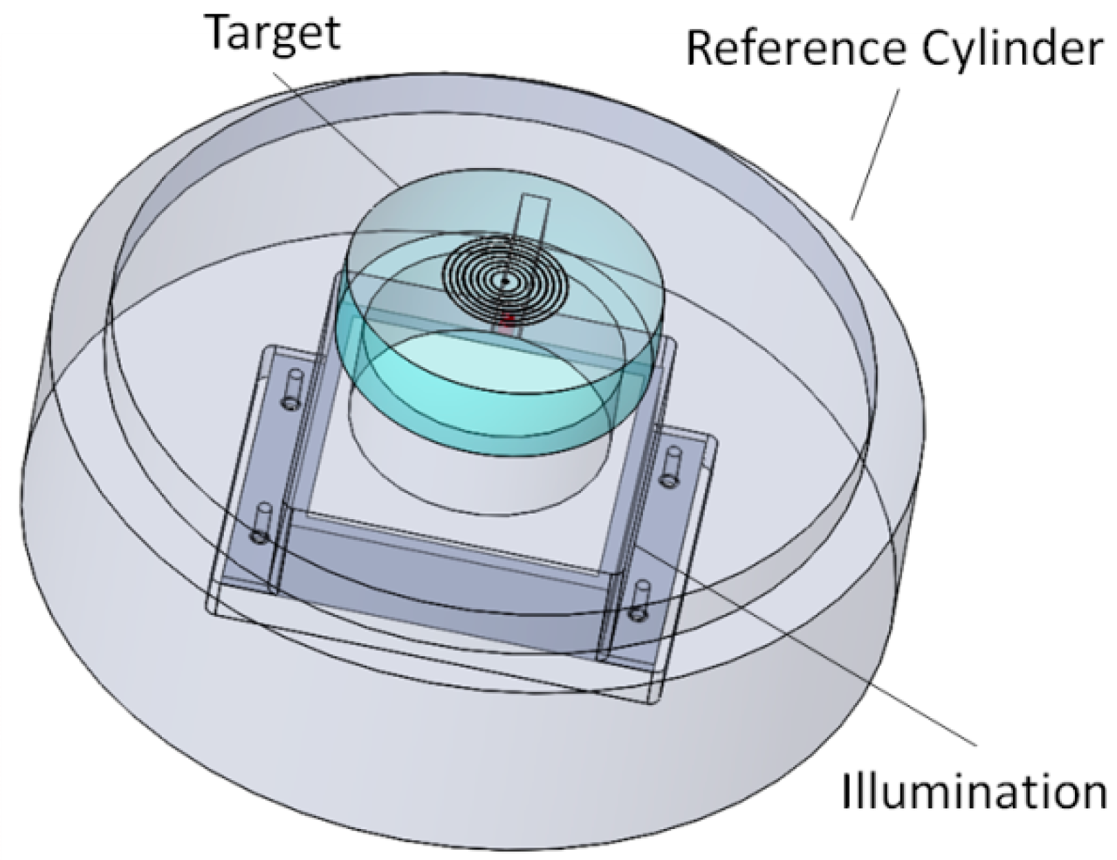
The optical target for MAT is mounted on a hollow reference cylinder (see Figure 2). An OGP SmartScope ZIP 250 vision measuring system (maximum permissible error (MPE): 1.8 + 6 L/1000 µm, where L is the measured length in mm) is used to measure the eccentricity between the target and reference cylinder. The vision measuring system measures the reference cylinder’s outer edge (roundness is 3 μm) and analyzes cylinder’s center position, then it aims at the central circular dot of the target with a crossline to determine the eccentricity. The eccentricity is measured and adjusted to 3 μm in x direction and −2 μm in y direction. A rectangular light emitting diode (LED) is fixed in the reference cylinder and it provides uniform illumination light which is suitable for observation.
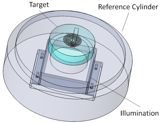
Figure 2.
Target for MAT mounted on a hollow reference cylinder.
An API Radian laser tracker (range: 40 m) [6] is used to align the target to mirror’s mechanical center. The laser tracker is placed 2.5 m away from the mirror’s mechanical center. The laser tracker measures the outer edge of the mirror and the reference cylinder and analyzes center positions respectively. The eccentricity of two center positions is repeatedly measured and adjusted. The MPE of laser tracker is 10 + 5 L μm (L is measured length in m) and the eccentricity of two center positions is finally controlled within 50 μm.
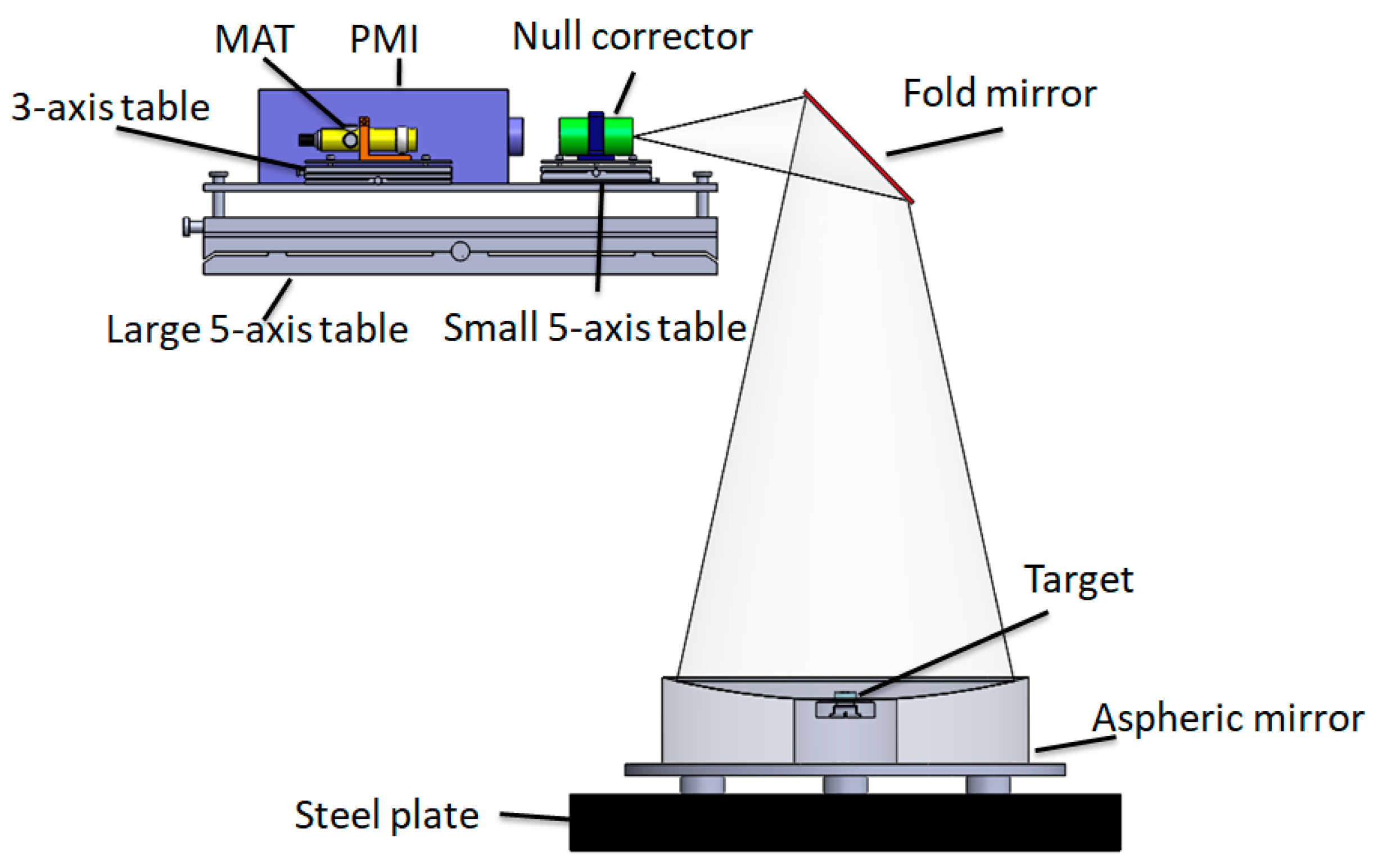
A Zygo GPI-XP/DPMI (test beam diameter: 4 inch) [7] is placed horizontally on the test tower with a 45° fold mirror which makes easy to align the optical path of heavy PMI system (see Figure 3). To align the optical path, a large 5-axis table which enables precision translation in the X, Y and Z axes, as well as tip-tilt adjustment for the PMI measurement is used. The refractive null corrector is also placed on the large 5-axis table and it is aligned to the PMI with a small 5-axis table by using interference fringe in the first place, then the large 5-axis table is precisely adjusted to align the optical path until the residual coma and defocus terms are within 0.2λ.

Figure 3.
Setup to measure vertex position of aspheric mirror.
A MAT with built in optical micrometers (graduations: 0.02 mm, error: ±0.002 mm) from Taylor Hobson [8] is used to observe the lateral displacements of the target, as shown in Figure 3, the MAT is placed beside the PMI on a small 3-axis table, 3 m away from the mirror. The angle between the PMI axis and MAT axis is approximately 7 degrees in x direction, due to ‘Cosine error’, the actual displacement in x direction was 1.01 times the measured displacement. The measurement results are listed in Table 1.

Table 1.
Results of the vertex position measurement. xtar-ref, ytar-ref are displacements between the target center and reference cylinder center in x, y directions; xref-mir, yref-mir are displacements between the reference cylinder center and mirror center in x, y directions.
The measurement uncertainty analysis is as follows:
The measurement model for the vertex position is shown in Equation (1), while in the experiment,
The uncertainty model of the vertex position measurement is shown in Equation (3) [9]:
uvertex2 = umat2/2 + ucoma2/2 + utar-ref2 + uref-mir2
According to the MPE value of the SmartScope ZIP 250 (assigning rectangular distribution), the displacement between the target center and reference cylinder center measurement uncertainty is (Type B evaluation of uncertainty):
utar-ref = 2 μm
According to the MPE value of the API Radian laser tracker (assigning rectangular distribution), the displacement between the reference cylinder center and mirror center measurement uncertainty induced by the laser tracker is (Type B evaluation of uncertainty):
uref-mir_lt = 14 μm
The displacement between the reference cylinder center and the mirror center measurement uncertainty evaluated by statistical analysis of 5 measurements is (Type A evaluation of uncertainty):
uref-mir_repeatability = 24 μm
According to the measurement experience, the surface coma measurement uncertainty is 60 nm, to this mirror, the correlation coefficient of measured coma and lateral displacement is 227. The measurement uncertainty induced by coma measurement is (Type B evaluation of uncertainty):
ucoma = 14 μm
The uncertainty arises from the MAT reading is evaluated by measuring a target which mounted on a linear slider at a 3 m range. The statistical analysis of the repeatability and ranging test gives (Type A evaluation of uncertainty):
umat_reading = 10 μm
The drift of relative orientation between the MAT axis and test optics axis is evaluated by the repeatability test. The statistical analysis of 6 times reading from the PMI and MAT (in an hour) gives (Type A evaluation of uncertainty):
umat_drift = 45 μm
The combined uncertainty of the vertex position measurement is as follows:
uvertex = ((umat_reading2 + umat_drift2)/2 + ucoma2/2 + utar-ref2 + uref-mir_lt2 + uref-mir_repeatability2)0.5 = 44 μm
The expanded uncertainty (k = 2) is as follows:
Uvertex = k × uvertex = 88 μm
The analysis indicates the vertex position expanded measurement uncertainty is 88 μm. For comparison, the mirror is also measured with a CMM (MPE: 2.2 + L/350 µm, where L is measured length in mm). The vertex position x displacement is −90 μm and y displacement is 170 μm. The vertex position measurement uncertainty of the CMM method is evaluated using statistical way (rotate the mirror 3 times by 90 degrees and use a CMM to measure the vertex position at 4 directions) and vertex position measurement uncertainty is 0.29 mm in x direction and 0.12 mm in y direction. Thus, the result of the proposed method is within the uncertainty of the CMM measurement.
4. Conclusions
We presented a method to use a PMI, a laser tracker, and a MAT to accurately measure the vertex position of an aspheric mirror. The MAT is adjusted with the PMI to maintain relative position and orientation, and it measures the displacements of the target placed on the mechanical center of the mirror which makes vertex position measurement more direct. This is a convenient way to measure the vertex position of an aspheric mirror, especially suitable for controlling the mirror’s vertex position during the polishing process. A validation experiment is performed on a concave aspheric mirror 1 m in diameter and 2.1 m in RoC and the experimental results are compared with that of CMM, the results have confirmed the feasibility of the proposed method.
Author Contributions
Methodology, L.J.; validation, L.J., C.L., and Y.J.; writing—original draft preparation, L.J.; investigation, Y.T.; resources, W.J.
Funding
This research was funded by Sichuan Province Science and Technology Support Program, grant number “2017GZ0072”.
Conflicts of Interest
The authors declare no conflict of interest.
References
- Sweeney, D.W.; Stepp, L.M. Overview of the Large Synoptic Survey Telescope project. In Proceedings of the SPIE Astronomical Telescopes + Instrumentation, Orlando, FL, USA, 24 May 2006; Volume 6267, p. 626706. [Google Scholar]
- Tuell, M.T.; Martin, H.M.; Burge, J.H.; Gressler, W.J.; Zhao, C. Optical testing of the LSST combined primary/tertiary mirror. In Proceedings of the SPIE Astronomical Telescopes + Instrumentation, San Diego, CA, USA, 27 June 2010; Volume 7739, p. 77392V. [Google Scholar]
- Martin, H.M.; Angel, J.R.P.; Angeli, G.Z.; Burge, J.H.; Gressler, W.; Kim, D.W.; Kingsley, J.S.; Law, K.; Liang, M.; Neill, D.; et al. Manufacture and final tests of the LSST monolithic primary/tertiary mirror. In Proceedings of the SPIE Astronomical Telescopes + Instrumentation, Edinburgh, UK, 26 June 2016; Volume 9912, p. 99120X. [Google Scholar]
- Martin, H.M.; Burge, J.H.; Cuerden, B.; Davison, W.B.; Kingsley, J.S.; Lutz, R.D.; Miller, S.M.; Tuell, M. Manufacture of a combined primary and tertiary mirror for the Large Synoptic Survey Telescope. In Proceedings of the SPIE Advanced Optical and Mechanical Technologies in Telescopes and Instrumentation, Marseille, France, 23 June 2008; Volume 7018, p. 70180G. [Google Scholar]
- Leach, R. Abbe Error/Offset. In CIRP Encyclopedia of Production Engineering; Springer: Berlin, Germany, 2014; pp. 1–4. [Google Scholar] [CrossRef]
- API Radian Laser Tracker. Available online: https://www.apisensor.com/products/3d-laser-tracker-systems/radian (accessed on 26 January 2019).
- Zygo Phase Measurement Interferometers. Available online: https://www.zygo.com/?/met/interferometers (accessed on 26 January 2019).
- Taylor Hobson Micro Alignment Telescope. Available online: https://www.taylor-hobson.com/products/alignment-level/micro-alignment-telescopes/micro-alignment-telescopes-with-built-in-optical-micrometers (accessed on 26 January 2019).
- JCGM100: 2008. Evaluation of Measurement Data. Available online: http://www.iso.org/sites/JCGM/GUM/JCGM100/C045315e-html/C045315e.html?csnumber=50461 (accessed on 26 January 2019).
© 2019 by the authors. Licensee MDPI, Basel, Switzerland. This article is an open access article distributed under the terms and conditions of the Creative Commons Attribution (CC BY) license (http://creativecommons.org/licenses/by/4.0/).